
How to Configure Network Client Sampling on Meraki MS Switches
Overview
This article explains how to configure network client sampling on Cisco Meraki MS switches. Correct configuration ensures accurate client tracking, location reporting, and traffic analytics.
By default, Meraki MS switches disable sampling of clients and traffic on detected uplink interfaces. This keeps reporting data accurate. The discovery mechanisms identify MS-to-MS links and disable sampling dynamically.
This works well for end-to-end Meraki networks. However, accuracy can drop in two cases:
-
Networks that contain any intermediary devices.
-
Catalyst + Meraki deployments.
In these cases, client connectivity and locations can become inaccurate.
To address this, Meraki introduced a setting that lets you statically control sampling. You configure it under Switching > Switch settings.
Any new networks created as of May 15th, 2023 use a new default. This default disables sampling on all uplinks.
You can change this behavior if needed. For example, you may want to track clients connected to a non-Meraki switch upstream. In that case, enable Sample all interfaces. Meraki then samples on any non MS-to-MS uplinks.
Enabling sampling on all interfaces can reduce the accuracy of client locations. This is most likely when the uplink is an aggregation point for multiple MS devices in an L2 topology.
How sampling has worked historically
In an MS network, the Client details page reports the client's last known switch and port number.

This Dashboard information uses the most recent MS switch to see the source MAC address of the client. The switch reports the port where the client ingressed.
A client's last known port can change frequently. It can appear on different MS uplink ports when the device does not connect directly to an MS switch.
Example: wired client through a non-Meraki switch
Consider a network with MS switches and non-Meraki switches. Frames from devices on the non-Meraki switch must ingress an MS switch to reach their destination, as per the diagram below:
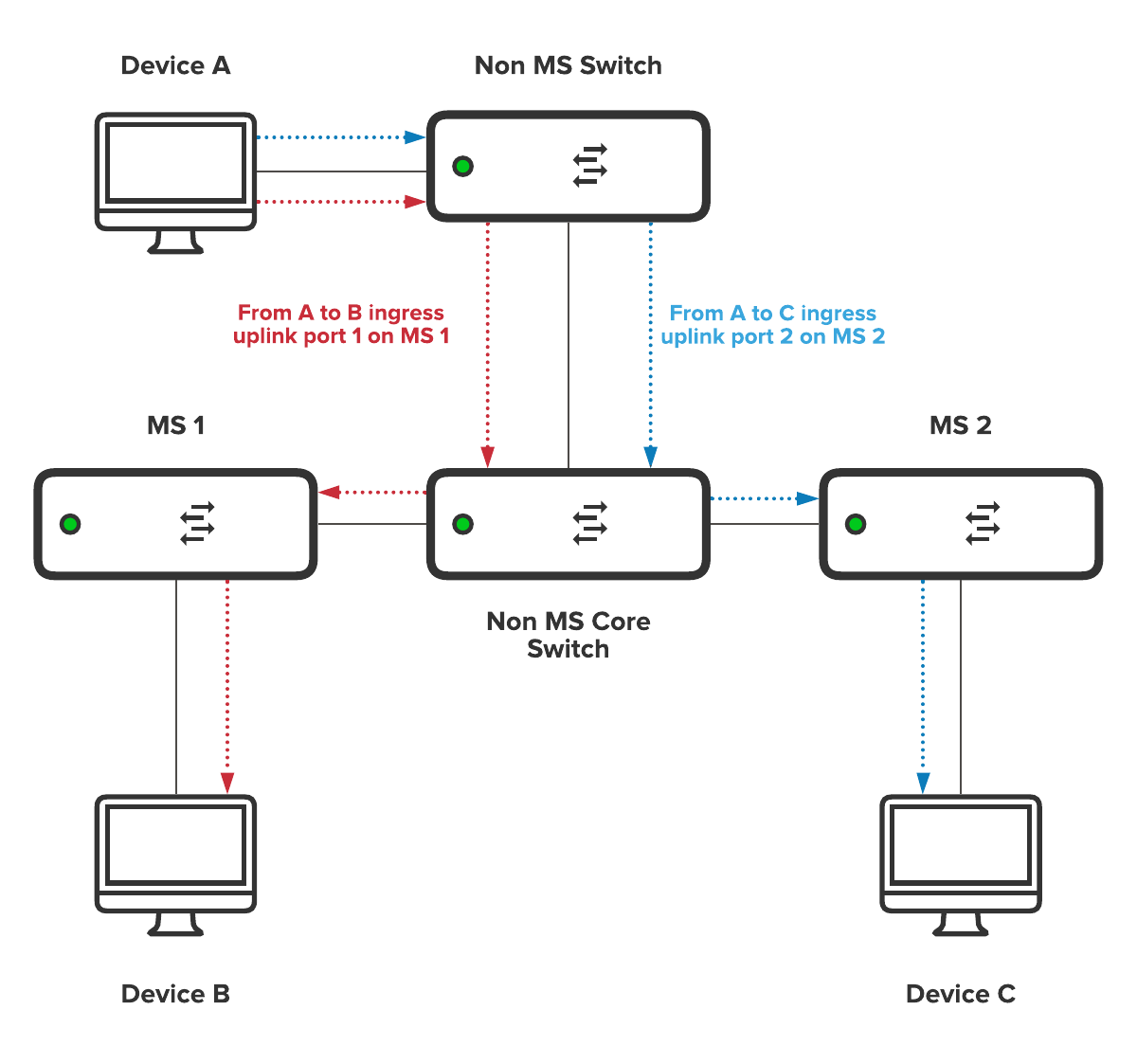
In above figure:
-
Device A sends a frame to device B. The frame ingresses MS-1 port 1. Meraki reports this as last seen.
-
Device A then sends a frame to device C. The frame ingresses MS-2 port 2. The last seen location changes to this switch and port.
Example: roaming wireless client
A wireless device can roam between APs connected to different MS switchports. The mobile client always appears as Last seen on the most recent switchport to receive its frames.

In the above figure, a mobile client moves from AP1 to AP2 to AP3. If the client sends data continuously, Meraki reports it in this order:
-
Seen on MS-1 port 1.
-
Last seen on MS-1 port 2.
-
Last seen on MS-2 port 1.
Step-by-step instructions
Use these steps to control client sampling on your MS switch uplinks.
-
In dashboard, refer to Switching > Switch settings.
-
Locate the client sampling setting.
-
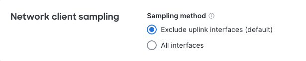
Choose one of the following options:
-
Exclude uplink interfaces (default) — disables client sampling on uplinks.
-
Sample all interfaces — enables client sampling on any non MS-to-MS uplinks. Use this to track clients connected to a non-Meraki switch upstream.
-
Select Save changes.
The feature is now live as a configuration option in Dashboard. Support intervention is no longer required to change this behavior.
Verification
Confirm your configuration applied correctly with the following check.
-
If you set sampling to Exclude uplink interfaces (default), packet captures on the uplink return no data. An empty result is expected behavior (MS-2376).