
Layer 3 Multicast and Troubleshooting
Overview
In several networks, sending multicast traffic across broadcast domains becomes necessary. The most likely scenarios will be where multicast sources and receivers are across different VLANs. This necessity to send multicast traffic across L3 boundaries is where Layer 3 multicast routing comes into play.
There are several multicast routing protocols. For the scope of this document, we will only focus on PIM-SM.
Protocol Independent Multicast (PIM)
What is PIM?
Protocol-Independent Multicast (PIM) is a family of multicast routing protocols that provide one-to-many and many-to-many distribution of data. PIM is "Protocol-Independent" as it does not rely on any specific unicast routing protocol and works with any existing unicast routing protocol (such as OSPF, RIP, or BGP).
To forward multicast traffic, PIM uses the information present in the unicast routing table to build a Multicast Routing Information Base (MRIB). PIM relies heavily on IGMP, allowing the hosts to inform the router of the multicast group membership.
PIM has five working modes: PIM Sparse Mode, PIM Dense Mode, Bidirectional PIM, PIM Source-Specific Multicast, and PIM Sparse-Dense Mode.
-
PIM Sparse Mode (PIM-SM): PIM-SM is suitable for large networks, especially those with few multicast subscribers or very dispersed distribution. PIM-SM is a "join protocol" mechanism where traffic is not forwarded on a segment unless an explicit request originates from the network segment.
-
PIM Dense Mode (PIM-DM): This mode is suitable for small networks or situations where multicast listeners are very dense, and most of the network subnets should receive the multicast traffic. PIM-DM is a "flood and prune" mechanism where PIM-DM spreads the multicast stream everywhere and then prunes the unnecessary parts to optimize delivery.
-
Bidirectional PIM (Bidir-PIM): This mode suits scenarios where multiple sources transmit data to multiple receivers. It’s a variant of PIM-SM.
-
PIM Source-Specific Multicast (PIM-SSM): Suitable for one-to-many communication mode, where a specific source sends multicast traffic to a clear set of recipients. Only receivers who explicitly request the multicast traffic from this source will receive it, ensuring optimal bandwidth utilization.
Note: As the receivers in the other mode don't care what source they receive multicast traffic from, multicast modes using IGMPv2 are also known as ASM (Any Source Multicast).
-
PIM Sparse-Dense Mode: In this mode, the interface is treated as dense mode if the group is in dense mode and as sparse mode if the group is in sparse mode.
Note: The Meraki Switch platform only supports PIM-SM.
Understanding the PIM-SM Process
PIM-SM - Rendezvous Point Tree
A Rendezvous Point Tree (RPT) is the path between a Rendezvous Point (RP) and the receivers in a multicast group. The RPT results from multicast routers joining the RP by sending PIM Join messages upstream to reach the RP of the topology. The RPT is also known as a shared distribution tree. Each multicast group may have different sources and receivers, so we may have multiple RPTs on the network. Here's how an RPT is built:
Note: Multicast in each L2 domain functions as described in the "L2 Multicast" section above, relying on IGMP.
-
In response to an IGMP Join from the receiver, a multicast router (receiver-side DR) generates and sends a PIM Join toward the RP.
-
Similarly, when multicast traffic reaches the upstream multicast router (source-side DR), it would encapsulate part of the multicast stream from the source in a PIM Register message and unicast it to the RP.
-
When the RP sees a Join (IGMP Membership Report or PIM Join) from an interested receiver, it will allow the multicast traffic from the sender to the receiver.
-
Note that the RP allows multicast traffic from the source to the receiver by sending a PIM Join to the source. This PIM Join allows the source-side DR to send multicast traffic without encapsulating the stream.
-
During this, the RP also sends a PIM Register-Stop to stop the PIM Registers from the source-side DR.
-
-
If the RP has not seen a Join, it will reject the PIM Register message with a PIM Register-stop and temporarily suppress the source switch/router from trying to send the multicast traffic to the RP.
RP 192.168.10.2 is sending a PIM Register-stop
Note: PIM relies on the unicast routing table when determining where to send the PIM Joins/Prunes and Registers/Register-stops.

Rendezvous Point Tree (RPT)

Switch 1 (RP) does not have a Join for group 239.1.1.1 and, as such, sends a PIM Register-stop to Switch 2
PIM-SM - Shortest Path Tree
-
Once multicast traffic begins flowing through the Rendezvous Point Tree (or RPT), the receiver-side DR learns the source IP of the multicast stream. At this point, the receiver-side DR performs a lookup of the source IP in the unicast routing table to determine if a shorter path exists. If a shorter path exists between the sender and receiver, the receiver-side DR will send PIM Joins towards the source.
-
The multicast stream can now flow between sender and receiver without passing through the RP (Shortest Path Tree or SPT).
-
Since the receiver-side DR is now receiving multicast traffic through the SPT, it doesn’t need it from the RPT anymore. It will send PIM Prune messages to the RP, informing any routers in between that they can stop forwarding multicast traffic for this group.
.png?revision=1)
Shortest Path Tree (SPT)
PIM-SM - Reverse Path Forwarding
Reverse Path Forwarding (RPF) prevents multicast loops. Unlike unicast, routing in multicast depends on where the source is. PIM uses the unicast routing table to check what interface will be used to reach the source. If the multicast stream ingresses on a different interface than expected, PIM drops the stream.
PIM-SM - Expected Traffic Flow
As discussed above, multicast routing sends multicast traffic across L3 boundaries, and PIM relies heavily on IGMP. Multicast routers work with the device acting as the Rendezvous Point (RP) to route multicast traffic between different broadcast domains. The RP's role becomes essential when dealing with multiple L3 segments between the source and the receiver. When a single PIM router is present, it's essentially multicast routing on a stick where the RP points to itself.
A high-level overview of the expected traffic flow:
-
Multicast Routing is enabled, and PIM routers form neighbor adjacencies.
-
The server streams traffic to a specified multicast address.
-
The source-side DR will encapsulate part of the stream into a PIM-Register and forward it to the Rendezvous Point (RP).
-
If no clients are attempting to access the stream, the RP will respond with a PIM Register-stop, temporarily suppressing the source-side DR from sending the multicast traffic to the RP.
-
-
When a client attempts to access the stream, it will send an IGMP Membership Report, which the receiver-side DR receives, converts into a PIM Join, and forwards to the RP.
-
Note: Join/Prune messages are sent only if the next hop neighbor is a PIM neighbor.
-
-
The RP will now allow the multicast traffic from the sender to the receiver. At this point, the multicast stream must flow through the RP (RPT).
-
If a shorter path exists between the sender and receiver, the receiver-side DR will send PIM Joins towards the source. The multicast stream can now flow between sender and receiver without passing through the RP (SPT).
The following topology will be used for our example:

Note: It's recommended that the Multicast Source be placed in the same subnet as the Rendezvous Point. This is to prevent PIM Registers from being sent and reduce network overhead. However, this topology is being used to show the complete traffic flow associated with PIM-SM.
Step 1:
Once Multicast Routing has been enabled on an SVI, PIM Hellos will be sent to the multicast address 224.0.0.13. This is to discover and form adjacencies with PIM Neighbors.

You can find the current PIM Neighbors by selecting the switch in question under Switch > Monitor > Switches and running Multicast Routing under the Tools tab.

Note: In order for multicast traffic to traverse L3 boundaries, Multicast Routing must be enabled on the entire path between Sender and RP, as well as Receiver and RP, with adjacencies formed across each segment.
Step 2:
The server initiates the stream to the multicast address of 239.1.1.70:

Step 3:
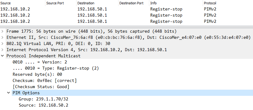
The source-side DR switch encapsulates part of the stream into a PIM-Register and forwards it to the RP. While the Destination IP is 239.1.1.70, the Destination MAC will be the MAC of the RP, or the next-hop MAC until it reaches the RP:

At first, no client attempted to access the stream, so the RP responded with a PIM Register-Stop. Expanding the PIM Options, the example source (192.168.50.2) and group (239.1.1.70) addresses can be seen:
Step 4:
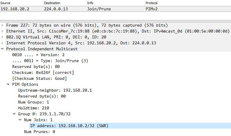
A client attempts to access the stream by sending an IGMP Membership Report for 239.1.1.70.

A PIM Join is generated and sent to the RP. This is evident by the IP of our RP (192.168.10.2) as shown below:
Step 5:
Upon receipt of the PIM Join, the RP will now forward the multicast traffic down towards the client requesting the stream.

Topics to know
PIM-SM - PIM Prune Override
On point-to-point links, there is only one other multicast router on the other end, so when the RP receives a prune message, it’s safe to stop forwarding the traffic. However, the RP may have more than one downstream multicast router interested in receiving the multicast traffic on multi-access links. When the RP receives a prune on a multi-access link, it must ensure no other multicast router still wants to receive the multicast stream. The RP does this with the PIM Prune Override mechanism.
When the RP receives a PIM Prune, it sets a 3-second timer on the interface before pruning, and due to the nature of a multi-access network, another multicast router using the multicast group traffic will also receive the prune message. This multicast router will send a Prune Override (Join) to the RP, causing the RP not to prune its interface.
PIM-SM - Neighbor Discovery and DR Election
In a PIM domain, each multicast router periodically sends multicast PIM Hello messages to all other multicast routers (destination address 224.0.0.13) on the local subnet(s) for which they are routing multicast. By exchanging Hello messages, all PIM routers on the subnet determine their PIM neighbors.

PIM router is sending a PIM Hello
PIM-SM requires a designated router (DR) on the source- and receiver-side networks. A source-side DR acts on behalf of the multicast source to send Register messages to the RP. The receiver-side DR acts on behalf of the multicast receivers to send Join messages to the RP.

Source DR 192.168.50.2 is sending a PIM Register

Receiver DR 192.168.20.2 is sending a PIM Join
The DR election process is as follows:
-
The multicast routers send Hello messages to one another, which contain the DR priority for DR election. The multicast router with the highest DR priority becomes the DR.
-
If the multicast routers have the same DR election priority, the multicast router with the highest IP address wins the DR election.
If the DR fails, the other routers will initiate the election of a new DR.
Multicast Router Discovery (MRD)
MRD is a protocol defined in RFC 4286.
To build the necessary PIM database, any SVI running PIM-SM must receive every IGMP packet and all multicast data streams inside the VLAN. Usually, a switch only forwards IGMP report packets out to the ports where IGMP queries are received, and data streams are similarly only sent out to ports with known receivers or ports where IGMP queries are received. Due to the IGMP Querier election, only one querier will be active per VLAN. So, if a VLAN has several PIM-enabled SVIs, only one will regularly transmit IGMP queries. The others will then fail to receive all IGMP packets and multicast data streams.
MRD solves this problem. PIM-enabled SVIs will also transmit regular MRD advertisement packets sent to 224.0.0.106. The reception port of MRD advertisement packets is also used to send all IGMP reports and data streams out, which solves the problem.
How to troubleshoot L3 multicast?
-
Check unicast traffic: Before troubleshooting multicast, ensure that unicast traffic is working.
-
Ping from the multicast receiver to the multicast source to test this.
-
Also, ping from the source gateway to the RP and from the receiver gateway to the RP.
-
-
Validate configuration:
-
For a multi-switch network, ensure the source and receiver subnets have an appropriate IGMP Querier.
-
The network must have a Rendezvous Point (RP).
-
The gateway for the source and receiver VLANs must be performing multicast routing.
-
Each router/switch between the source-side DR and the RP and the receiver-side DR and the RP must perform multicast routing for any transit VLAN.
-
-
Investigate multicast:
-
The multicast stream from the source and the Join (IGMP/PIM) from the receiver should reach the RP.
-
Common Issues 
RPF (Reverse Path Forwarding) Check
Reverse Path Forwarding is a loop-prevention mechanism that validates the source of a multicast stream. If the source of the stream ingresses on a different interface than expected, the stream will be dropped. This is typically introduced by a missing or misconfigured route to access the source of the stream.
Let's revisit our example topology but with an additional link added between the Client and Server switch (192.168.60.0/30). A static route has been configured on the Client switch so that the Sender (192.168.50.2) is reachable via this new link.

The Client switch will receive the multicast stream via the Client Transit (192.168.20.0/30) link, as this is where the PIM Neighbor Adjacency is formed. Upon receipt, the Client switch will check its unicast route table and see that the 192.168.50.0/24 subnet is reachable via the newly established link (192.168.60.0/30) instead. Because the path that the stream ingresses is different from the path that the Client switch would use to access the source of the stream, the RPF Check fails, and the stream is dropped.
There are two options available to resolve this:
- Adjust the static route on the Client switch so that the server subnet (192.168.50.0/24) is reachable via the Client Transit link (192.168.20.0/30)
- Enable Multicast Routing on the newly established link (192.168.60.0/30), and make sure that the Client and Server switch point to each other as the next hop to reach each other's subnets.
Note: For Option 2, the Multicast Stream would initially flow through the RP via the Shared Tree Path. After the Client switch receives the multicast stream, it'll send a PIM Join towards the source-side DR switch as it recognizes it as a more optimal path to reach the source of the stream. The path will then transition from the Shared Tree to Source Tree, allowing traffic to bypass the RP and flow directly between client and server.
TTL (Time-To-Live)
The TTL has been put in place to help reduce the impact of routing loops. The TTL value of a packet will decrease with every hop until it reaches a value of "0," in which it's then discarded. The TTL must be set to a value high enough to accommodate the number of hops between the multicast sender and receiver.
Some applications use a default TTL of "1" that will need to be adjusted, as a value of "1" indicates that the packet isn't routable. If there are issues with the application, the stream may also be sent with an incorrect value.
You can find the TTL by selecting any packet of the multicast stream and expanding its "IPv4" section. Below, we can see the TTL of the stream was set to "100:"