
MT40 Installation Guide - Smart Power Controller
Overview
The Cisco Meraki MT40 sensor is a cloud-managed Smart In-line power monitoring sensor that is exceptionally simple to deploy and configure due to its integration into the Meraki dashboard and the use of BLE technology. With both internal Meraki integrations and external integrations, the possibilities of what you can enable with MT40 are nearly endless.
Pre-Installation Preparation
The following steps before going on-site to perform an installation
Configure Your Network in Dashboard
The following is a brief overview of the steps required to add an MT40 to your network. For detailed instructions about creating, configuring and managing Meraki Sensor networks, refer to the online documentation (https://documentation.meraki.com/MT).
- Login to http://dashboard.meraki.com. If this is your first time, create a new account.
- Find the network to which you plan to add your sensor or create a new network.
- Add the sensors to your network. You will need your Meraki order number (found on your invoice) or the serial number of each sensor, which looks like Qxxx-xxxx-xxxx, and is found on the back of the unit or included in the box.
- Add the gateway (MV or MR) to the same network as the sensor.
Make sure the gateway is in the same network and is online and operational
Minimum Firmware Version
| MT | MV | MR |
| 1.4.1 | 5.3 | 29.6.1 |
The minimum firmware version for MT40 is different from other MT sensors. While MT40 will still be operational on lower firmware versions, some features might not be available.
Installation Instructions
In the Box
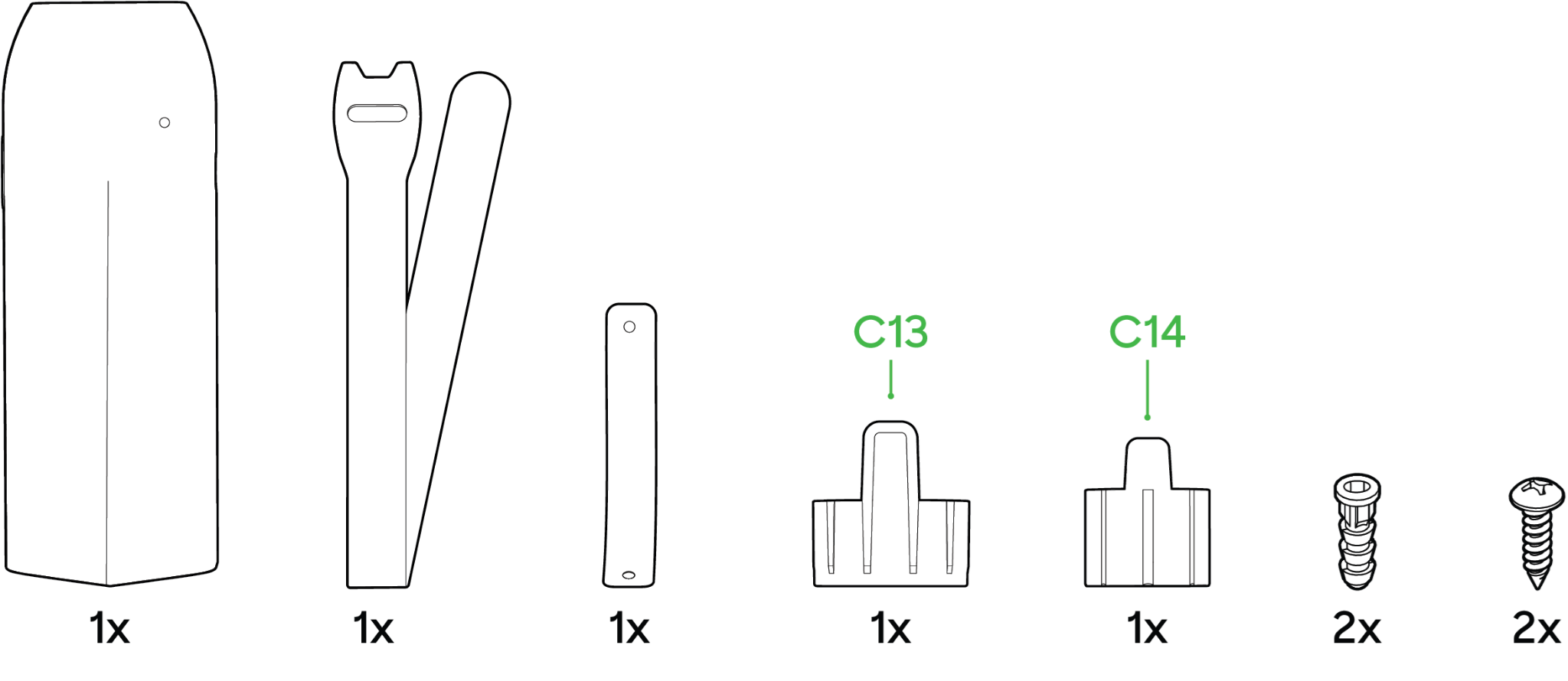
- MT40 Sensor
- Velcro Mounting Strap
- Mounting Bracket
- Mounting Anchor and Screws
- C13 and C14 Cable Retention Sleeves
Choosing Your Mounting Location
For most mounting scenarios, the MT40 has a flexible option to provide quick and simple mounting. The MT40 can be used in place and is able to rest on any surface while being used, however we currently have 2 options for mounting the device.
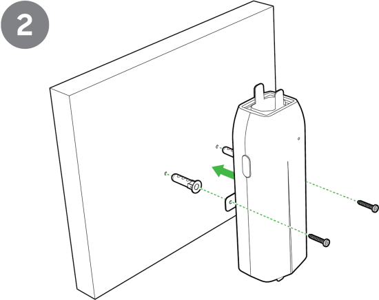
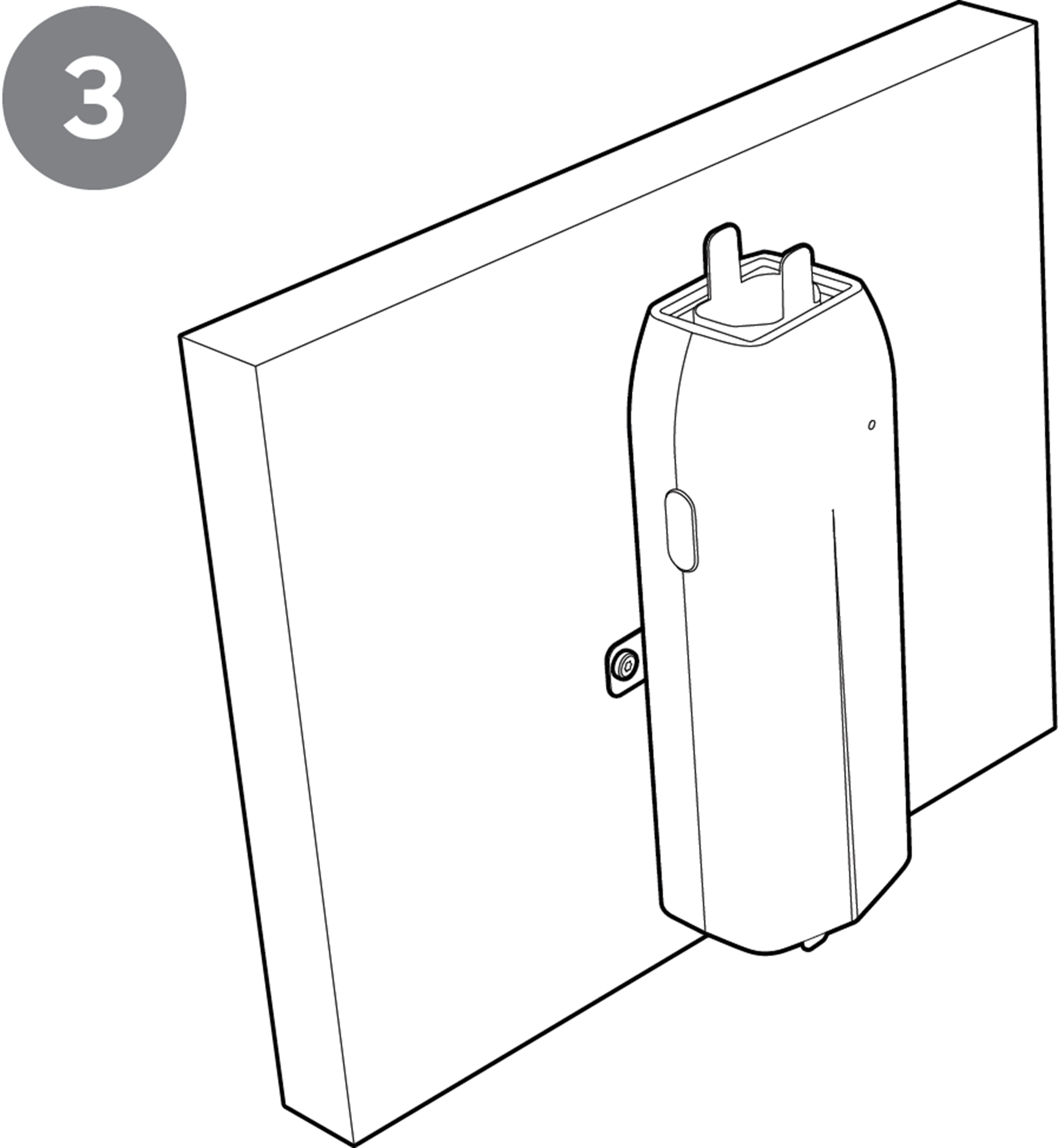
Wall Mount
The instructions are as follows:
- Attach the metal bracket through the holes in the bottom of the device.
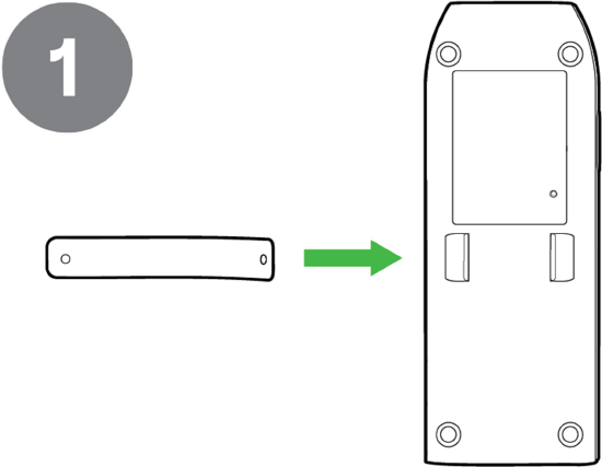
- Mount the sensor, a metal bracket needs to be screwed in on a flat surface such as drywall.
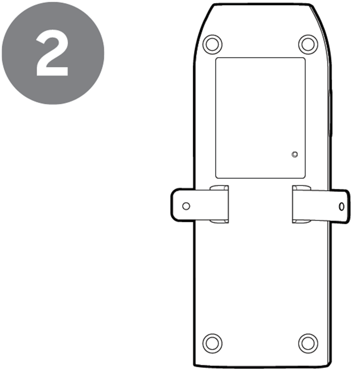
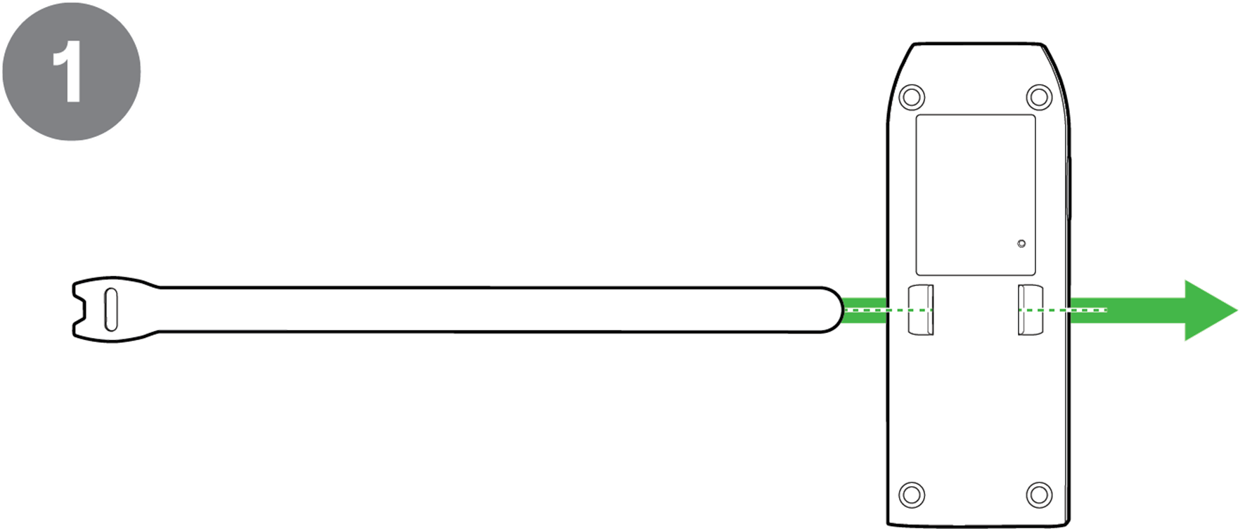
Pole or Rack Mount
The instructions are as follows:
- Start by attaching the sensor mounting straps through the holes in the bottom of the device.
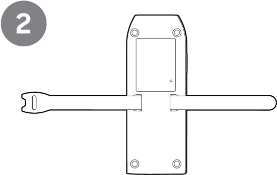
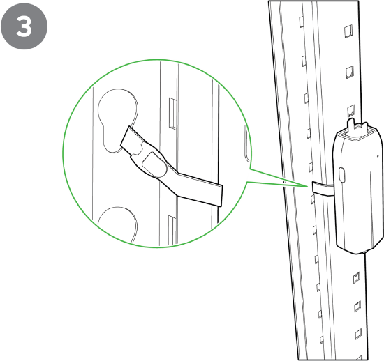
- In order to mount the sensor, the strap will need to be wrapped around a sturdy surface (such as the leg of a rack, a rail or a pillar).
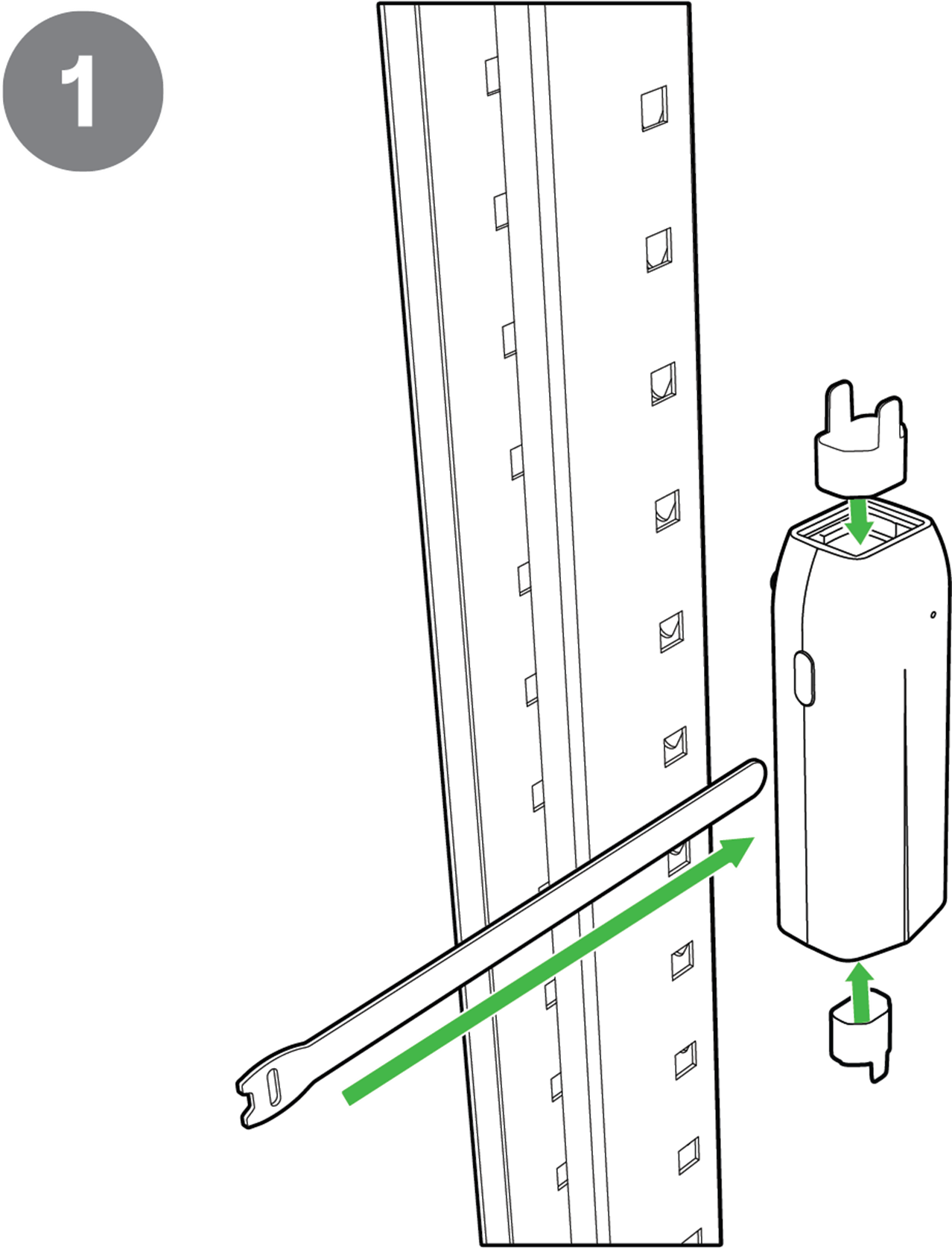
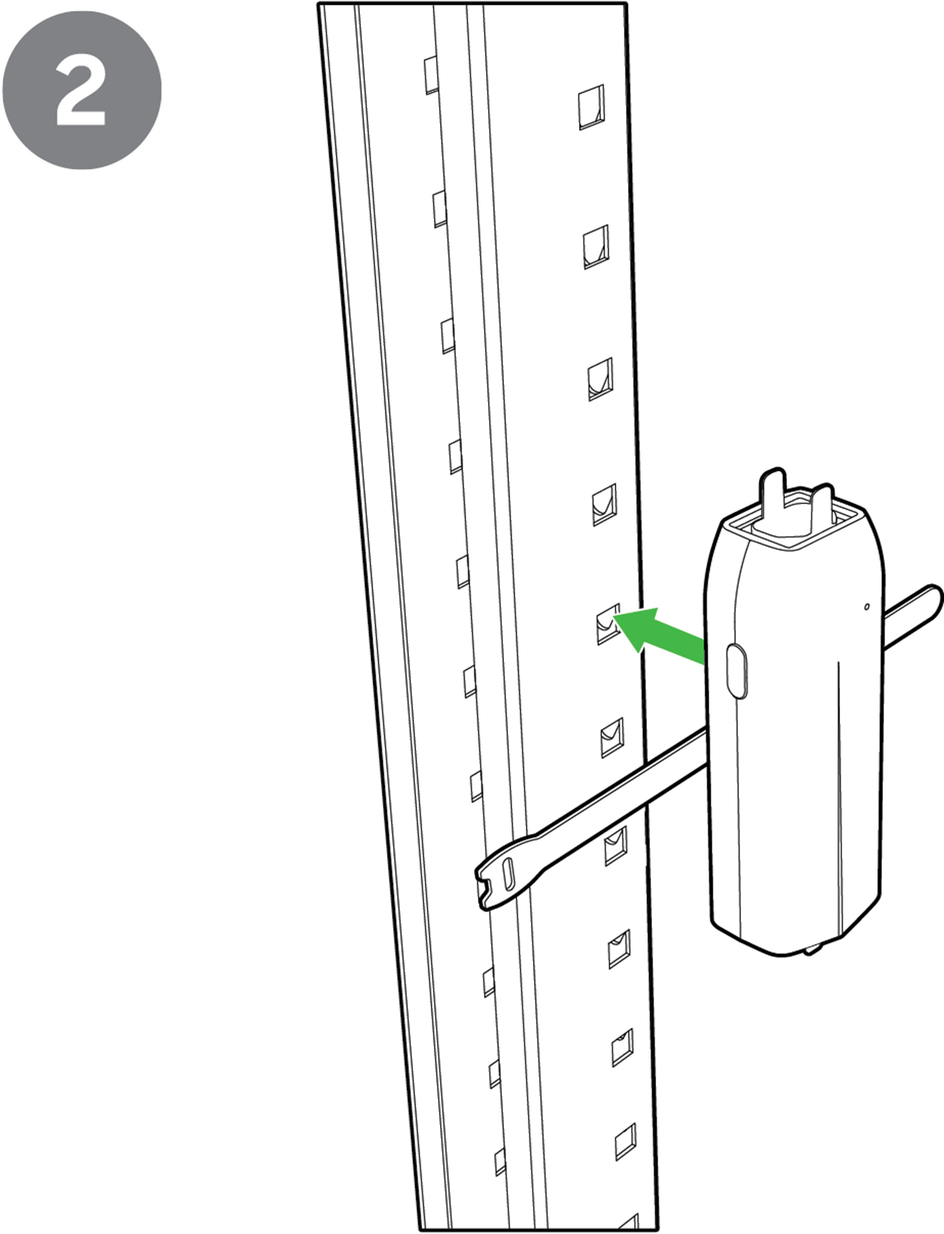
- Secure the mounting strap to ensure a strong hold.
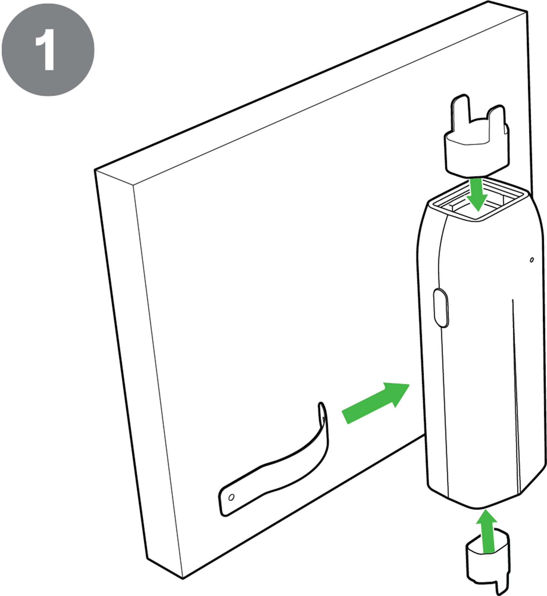
Powering the MT40
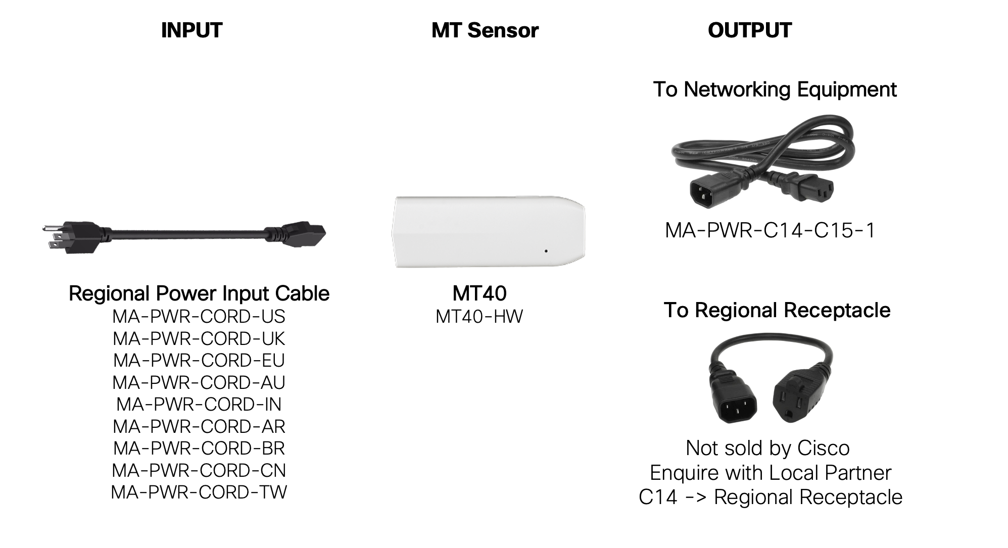
The MT40 has an input and an output for power to run through the device, shown in the image below:
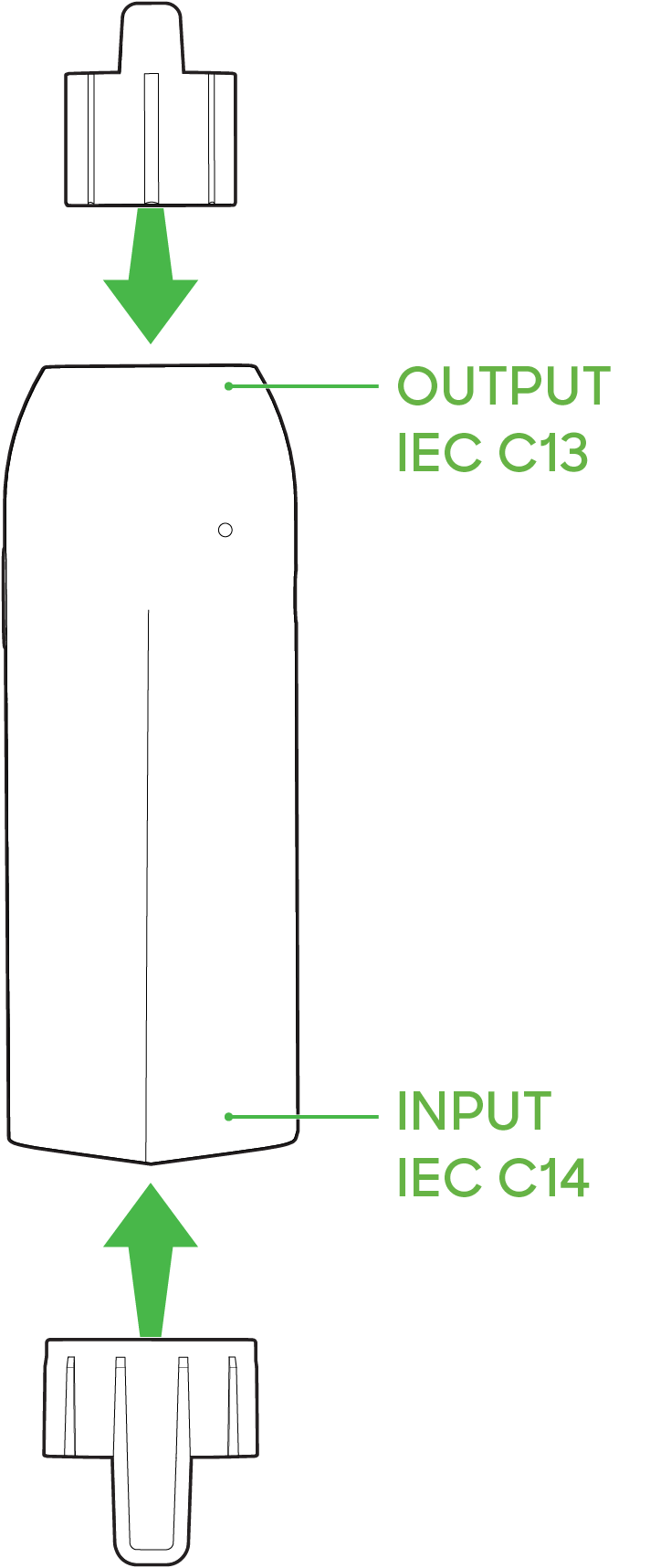
- Connect the output side to your device, using the necessary IEC C15 cable to your needed power termination. Some examples are
- C14 to C15 cable. Plugs into output of MT40 and into the input of IT devices like Cisco/Meraki products, PC's, computer monitors, etc.
- C14 to NEMA 5-15R cable. Plugs into output of MT40 and into the input of common electrical devices in North America
- When connecting the output power to the MT40, you have the option to use the included C15 connector sleeve to prevent the connector from accidentally being disconnected.
- Connect the input side of the MT40 to an IEC C14 cable, once there is a secure connection on the cable then connect the wall socket side to a power source (this is your MA-PWR-CBL-XX)
- When connecting the input power to the MT40, you have the option to use the included C15 connector sleeve to prevent the connector from accidentally being disconnected.
- The light on the sensor should appear as green once booted and connected, this helps you know that it is connected and talking to the Meraki Dashboard.
Physical Lock Out Switch
On the MT40 sensor, there is a turnable switch which will allow the user to lock remote control of the downstream power.
The lockout symbol can be seen in the image below:

Switch States:
- Lock - Disables Remote power control through the Dashboard. Downstream power cannot be controlled when the switch is locked.
- Unlock - Allows Remote power control through the Dashboard. Authorized Dashboard users(Organization or a Full Network Administrator) can issue commands to control downstream power.
The current switch state is also reflected in the dashboard UI under Power Controls tab
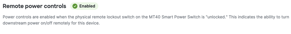
Enabled = Unlocked
Disabled = Lock
Default State
By default, MT40 downstream power state will always default to the last known command executed from the Dashboard.
For example, if a user turns off the Downstream Power of an MT40, the OFF state will persist after the reboot of the MT40 as well. This means that in case there’s an upstream power outage, the MT40 will keep the downstream state as OFF on power restore.
To override the state persistence in case Dashboard connectivity for sensor is not possible, a user can physically toggle the Lock Out switch.
LED Status
.png?revision=1&size=bestfit&width=795&height=590)
The LEDs on the MT40 has dual purpose:
Powered On
No LED = No Power Input
Rainbow = Initializing or Looking for Gateway
Solid 🟢 = Downstream Power Enabled
Solid 🟠 = Downstream Power Disabled
On Button Press
Rainbow then 🟢 = successful connection
Rainbow then 🟠 = unsuccessful connection
General Purpose Button 
The MT40 has a general-purpose button on the side, allowing you to wake up the sensor and test if it can connect to a gateway. This will also upload the latest sensor data to the gateway.
Factory Reset Button
On the back of the sensor, there is a sticker with the FCC information and the serial number, here you will find a pinhole button to factory reset the sensor. If the button is pressed and held for at least 5-15 seconds and then released, the sensor will reboot and it will be restored to its original factory settings by deleting all configuration information stored on the unit.
Support and Additional Information
If issues are encountered with device installation or additional help is required, contact Meraki Support by logging in to dashboard.meraki.com and opening a case by visiting the Get Help section.
For additional information on Meraki hardware and for other installation guides, please refer to documentation.meraki.com.