MV13 Installation Guide
MV13 Overview
The Cisco Meraki MV13 series are network cameras that are exceptionally simple to deploy and configure due to their integration into the Meraki Dashboard and cloud-augmented edge storage. The MV family eliminates complex and costly servers and video recorders required by traditional solutions, removing the limitations typically placed on video surveillance deployments.
Package Contents
In addition to the MV camera, the following are provided:

|
Unit |
MV13-HW MV13M-HW |
|---|---|
|
Mounting Equipment |
1 x T10 Torx key 1 x Small Mounting Plate 1 x Conduit Adapter |
MV13 series does not ship with mounting screws and anchors as an included accessory in the packaging content.
Screw Recommendation:
-
Type: Self-Tapping Screw
-
Size: M4
-
Length: Minimum 25mm
-
Screw head diameter: Maximum 10mm
-
Driver Type: ANY (eg: Philips)
-
Head Type: ANY (Eg: Pan Head)
-
Build Material: Stainless Steel
The insertion diameter of the anchor should be smaller than that of the screw, and the length of the anchor should be longer than that of the screw. The appropriate anchor should be selected based on the structure that it will be installed on, such as concrete, brick, wood, drywall, etc.
Powering the MV13 Series
The MV13 series features a 1000BASE-TX Ethernet port and requires 802.3af PoE minimally for operation. Route the Ethernet cable from an active PoE switch or injector port.
Power over Ethernet supports a maximum cable length of 300 ft (100 m).
Pre-Install Preparation
You should complete the following steps before going on-site to perform an installation:
Configure Your Network in the Dashboard
The following briefly overviews the steps required to add an MV13 series camera to your network. For detailed instructions about creating, configuring and managing Meraki Camera networks, refer to the online documentation (https://documentation.meraki.com/MV).
-
Login to http://dashboard.meraki.com. If this is your first time, create a new account.
-
Locate the network where you want to add your cameras or create a new one.
-
Add your cameras to the network using your Meraki order number from the invoice or the serial number on each camera. The serial number looks like Qxxx-xxxx-xxxx and is located on the bottom of the unit.
-
Verify that the camera is now listed under Cameras > Monitor > Cameras.
Check and Configure Firewall Settings
A firewall must allow outgoing connections on specific ports to certain IP addresses. Find the latest list of outbound ports and IP addresses for your organization under Help > Firewall Info on the dashboard.
DNS Configuration Best Practices for LAN Streaming
Each camera generates a unique domain name for secure direct streaming. These domain names resolve to an A record with the camera’s private IP address. Any public recursive DNS server can resolve this domain.
If utilizing an on-site DNS server, allow *.devices.meraki.direct or set a conditional forwarder to prevent local domains from appending to *.devices.meraki.direct and forward these domain requests to Google public DNS.
Assigning IP Addresses
The MV13 series camera does not support static IP addresses. MV13 units must be connected to a subnet with DHCP and have available DHCP addresses to operate correctly.
Installation Instructions
The MV13 series will automatically update to the latest stable firmware during a first-time setup. Some features may be available once this automatic update is completed. This process may take up to 5 minutes to enable whole disk encryption. The state of this process can be monitored by referencing the MV LED Status.
Mounting Instructions
The MV13 wall mount offers a quick, simple, and flexible way to mount your device in most scenarios. Installation involves a few easy steps.
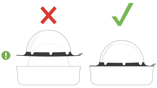
Leave the protective plastic cover on the optical dome during installation to prevent damage. Remove the cover after installation is complete.
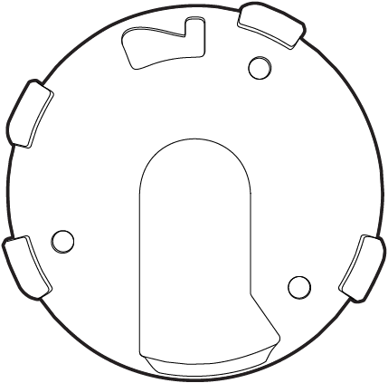
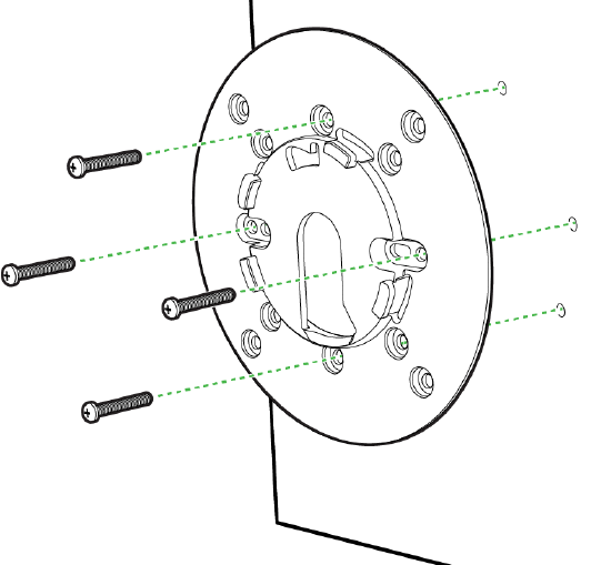
1. Use the template to determine mounting hole locations for wall mounting before screwing in the base mount plate.
2. Peel backing from the mounting template to stick on the wall.
3. Use template holes marked with the letter “A” for standard wall mounting.
4. Screw the base mount plate onto the wall in pre-determined locations using the provided wall screws.
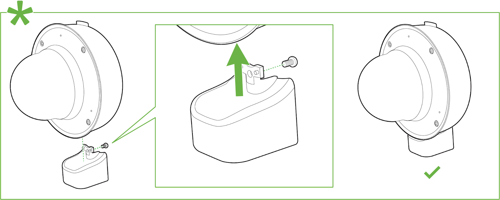
Installing the conduit box to MV13 series: (optional)
Microphone Cut-off Switch & Factory Reset Button
The MV13 has a new microphone cut-off switch at the camera's base. This switch can be used to disable audio and override the Dashboard Audio Settings for an added layer of security. If the regulations require disabling audio or Dashboard control for Audio enablement needs to be disabled, the microphone cut-off switch can be leveraged and set to Disabled.
If the microphone switch is disabled and the camera is mounted, toggling the switch back ON would require accessing the camera's base.
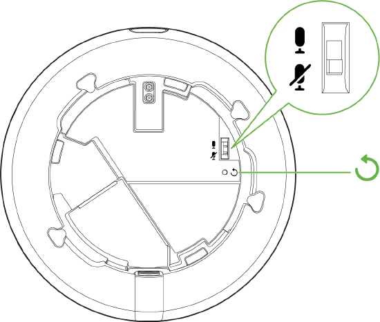
The MV13 also features a Factory Reset button which lies right under the microphone cut-off switch. This reset function can be activated by inserting a reset pin into this section for 15 seconds.
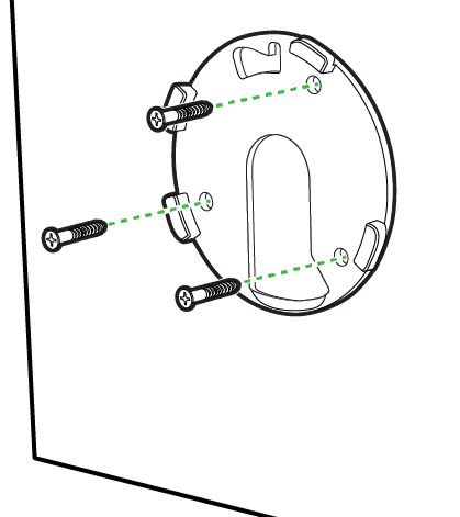
MV13 Install using the small mounting plate
Refer to the guidelines for mounting the base plate on any surface or on top of a mounting accessory.

- Use 3x Wall anchor and screws to fix the base plate to the wall.
-
Mount the small base plate onto the wall surface using the paper template provided.
-
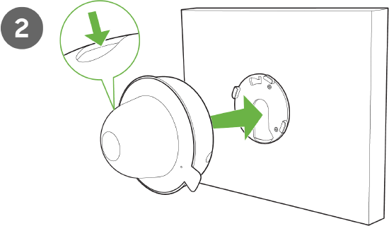
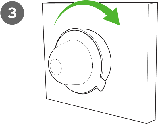
The MV13 Series cameras have a button to engage the locking mechanism. Press the button while aligning the MV13 to the small base plate.
-
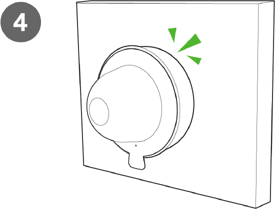
Twist the camera while holding the button until a click is heard.
-
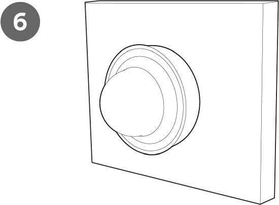
The camera is locked onto the plate and secured.
-
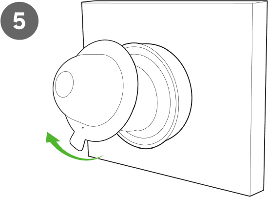
Remove the protective cover
The MV13 Series cameras have a button to engage the locking mechanism. Press the button while aligning the MV13 series to the base plate.
Check the status LED on the left side of the camera lens. Make sure the camera is connected via Ethernet (solid green) or WiFi (solid blue). You must first set up the MV camera using a wired Ethernet connection before using it wirelessly. Refer to the setup guide for WiFi connection instructions.
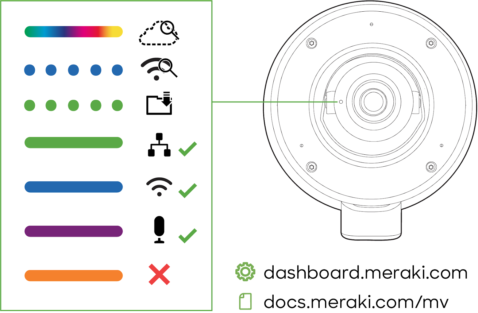
MV13 LED Status Indicator
Your MV13 series is equipped with an LED light on the front of the unit to convey system functionality and performance information.
The following colours and patterns indicate the various status conditions of an MV:
-
Rainbow (solid, rotating through colours) - MV is booting up.
-
Flashing Blue - MV is searching for WiFi network(s).
-
Flashing Green - MV is upgrading or initializing for the first time.
-
Solid Green - MV is connected via Ethernet.
-
Solid Blue - MV is connected via WiFi.
-
Solid Violet - MV has audio recording enabled.
-
Solid Amber - MV is not able to connect to the Dashboard.
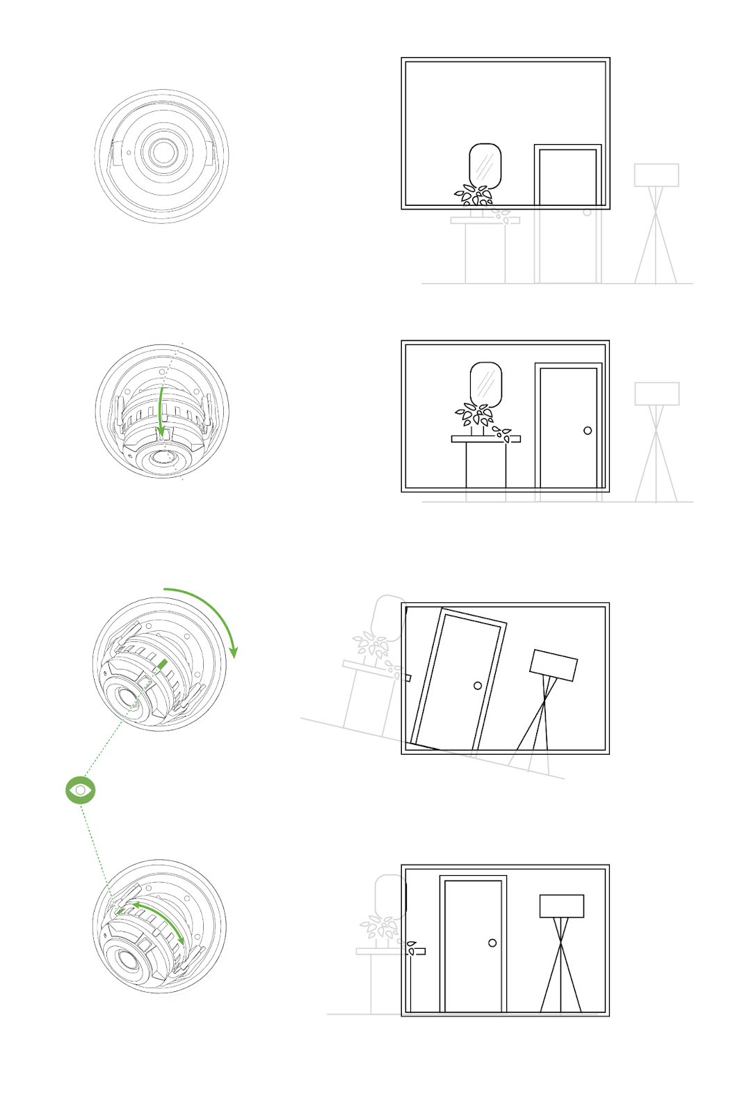
6. Aim the lens by looking through the camera on the Meraki Dashboard to fine-tune the picture. The camera sensor and lens can be tilted up to 65 degrees, rotated ±90 degrees, and panned 354 degrees. The image can be rotated 180 degrees in software only. No other physical adjustments are possible. Zoom and focus can not be adjusted on the camera.
Never adjust or remove the rubber lens gasket or protective lens guard.