
MV84X Installation Guide
This is a comprehensive guide for the MV84X camera, detailing its overview, power requirements, dashboard setup, and step-by-step installation instructions.
MV84X Overview
The Cisco Meraki MV84X is a multi-imager smart camera that is exceptionally simple to deploy and configure due to its integration into the Meraki dashboard and cloud-augmented edge storage. The MV Smart Camera family eliminates complex and expensive servers and video recorders required by traditional solutions, removing the limitations typically placed on video surveillance deployments.
.png?revision=1&size=bestfit&width=720&height=263)
What’s In the Box?
The following items are included with the MV84X.

Verify that all contents are present before beginning installation.
| Item | Specification | Quantity |
|---|---|---|
|
Camera |
MV84X | 1 |
|
Camera Ceiling Base Plate |
- | 1 |
|
IR Shield |
- | 1 |
|
Installation Template |
- | 1 |
|
Screw |
M6x15 | 3 |
|
Screw |
M5x30 | 3 |
|
Anchor |
M5x50 | 3 |
|
Dessicant Pack |
- | 2 |
| Rubber Gasket (additional) | 6.3 - 8.3 mm | 1 |
|
Screwdriver |
Secure T10 Torx | 1 |
|
Wrench |
26mm C-Socket | 1 |
Powering the MV84X Camera
The MV84X features a 1000BASE-TX Ethernet port and requires 802.3bt Type 3 PoE++ for operation. Route the Ethernet cable from an active port on a Type 3 PoE++ switch or injector.
- Power over Ethernet supports a maximum cable length of 328 ft (100 m).
- The MV84X camera is capable of powering on with 802.3at (PoE+) when the IR illumination is disabled.
Pre-Install Preparation
You must complete the following steps before going on-site to perform an installation.
Configure Your Network in the Dashboard
The following is a brief overview of the steps required to add an MV84X camera to your network. For detailed instructions about creating, configuring and managing the Meraki Camera networks, refer to the MV - Smart Cameras documentation.
- Login to http://dashboard.meraki.com. If this is your first time, create a new account.
- Find the network to which you plan to add your cameras or create a new network.
- Add your cameras to your network. You will need your Meraki order number (found on your invoice) or the serial number of each camera, which looks like Qxxx-xxxx-xxxx and is found on the unit label.
- Verify that the camera is now listed under Cameras > Monitor > Cameras.
Check and Configure Firewall Settings
If a firewall is in place, it must allow outgoing connections on particular ports to IP addresses. The most current list of outbound ports and IP addresses for your organization can be found under Help > Firewall Info on the dashboard.
DNS Configuration Best Practices for LAN Streaming
Each camera will generate a unique domain name for secured direct streaming functionality. These domain names resolve an A record for the private IP address of the camera. Any public recursive DNS server will resolve this domain.
If utilizing an on-site DNS server, please allow *.devices.meraki.direct or configure a conditional forwarder so that local domains are not appended to *.devices.meraki.direct and that these domain requests are forwarded to Google public DNS.
Assigning IP Addresses
Currently, the MV84X camera does not support static IP assignment. MV84X units must be added to a subnet that uses DHCP and has a pool of available DHCP addresses to operate correctly.
Mounting Instructions
If you are mounting the MV84X with additional accessories like a Wall Arm, Corner mount, Junction Box, Pole mount or the Parapet mount, please review the MV84X Mounting Options and Guidelines along with this installation document.
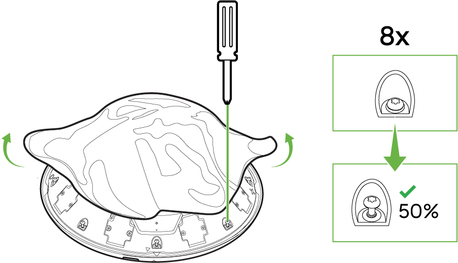
Step 1: Loosen the Dome Housing Screws
-
Using the provided T10 torx security-bit screwdriver, locate the eight (8) perimeter screws around the MV84X dome housing.
-
Loosen each screw to about 50%—AVOID removing them completely. This will allow the lifting or removal of the dome cover without losing the screws.
-
-
Ensure the screws remain securely in their slots so they don’t fall out during the following steps.
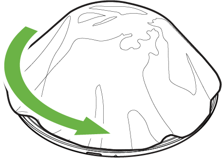
Step 2: Rotate and Remove the Dome Cover
-
After partially loosening the eight perimeter screws in Step 1, gently rotate the dome cover in the direction indicated by the arrow.
-
The dome will disengage when the arrows on the dome and the base plate aligns.
-
Carefully lift the dome cover away from the rest of the housing.
Tip: If the dome doesn’t move freely, ensure each screw is loosened enough to allow rotation, but not too loose that it detaches from the base.
Step 3: Lift the Dome Housing

-
After rotating the dome in Step 2, carefully lift the dome housing straight up, as shown by the green arrows.
-
The dome is secured to the camera using a cable. Place the dome on the side while keeping the cable attached.
-
Verify that the internal assemblies (imagers, lenses, etc) remain secure and unobstructed.
Important: Avoid touching sensitive components inside the camera. Smudges or debris on the lenses can impact video quality.
Step 4: Unlock and Rotate the Camera Base

-
On the camera base plate, you’ll see a small button, gently press to unlock the camera from the base plate.
-
Turn the camera assembly in the direction of the green arrow to completely disengage the camera from the base plate.
Step 5: Detach the Mounting Plate

-
After completing the previous unlock/rotation step (Step 4), ensure the base is in the “unlock” position.
-
Separate the mounting plate (the large circular piece) away from the main camera assembly, as indicated by the upward arrows.
-
Place the mounting plate aside safely.
Step 6: Remove or Disassemble the Cable Gland

-
Locate C-Socket Nut on the camera base, this contains the cable gland assembly.
-
Unscrew the C-socket nut from the base of the camera. Use the provided wrench as needed.
-
Remove the seal basket (also known as a compression or seal ring) and the rubber gasket.
Keep these pieces safe and organized as they will be used later for reinstallation.
Step 7: Mount the Plate and Route the Cable

-
Prepare the Cable Opening
-
Ensure the hole in the ceiling or wall is large enough for your cable and connectors (e.g., RJ45 plug).
-
If using anchors, insert them into pre-drilled holes in the ceiling or wall.
-
-
Feed the Cable
-
Pull the cable through the hole, lining it up with the center opening of the mounting plate.
-
Confirm that you have enough slack on the camera side to attach or adjust the cable later. Note that at approximately 20cm of cable is needed for proper installation after the camera is locked into its mounting plate.
-
-
Align the Mounting Plate
-
Position the mounting plate against the ceiling or wall so the screw holes line up with the anchors (or pre-drilled holes).
-
-
Secure with Screws
-
Insert the appropriate screws (e.g., M5x30) through the mounting plate into the anchors or backing surface.
-
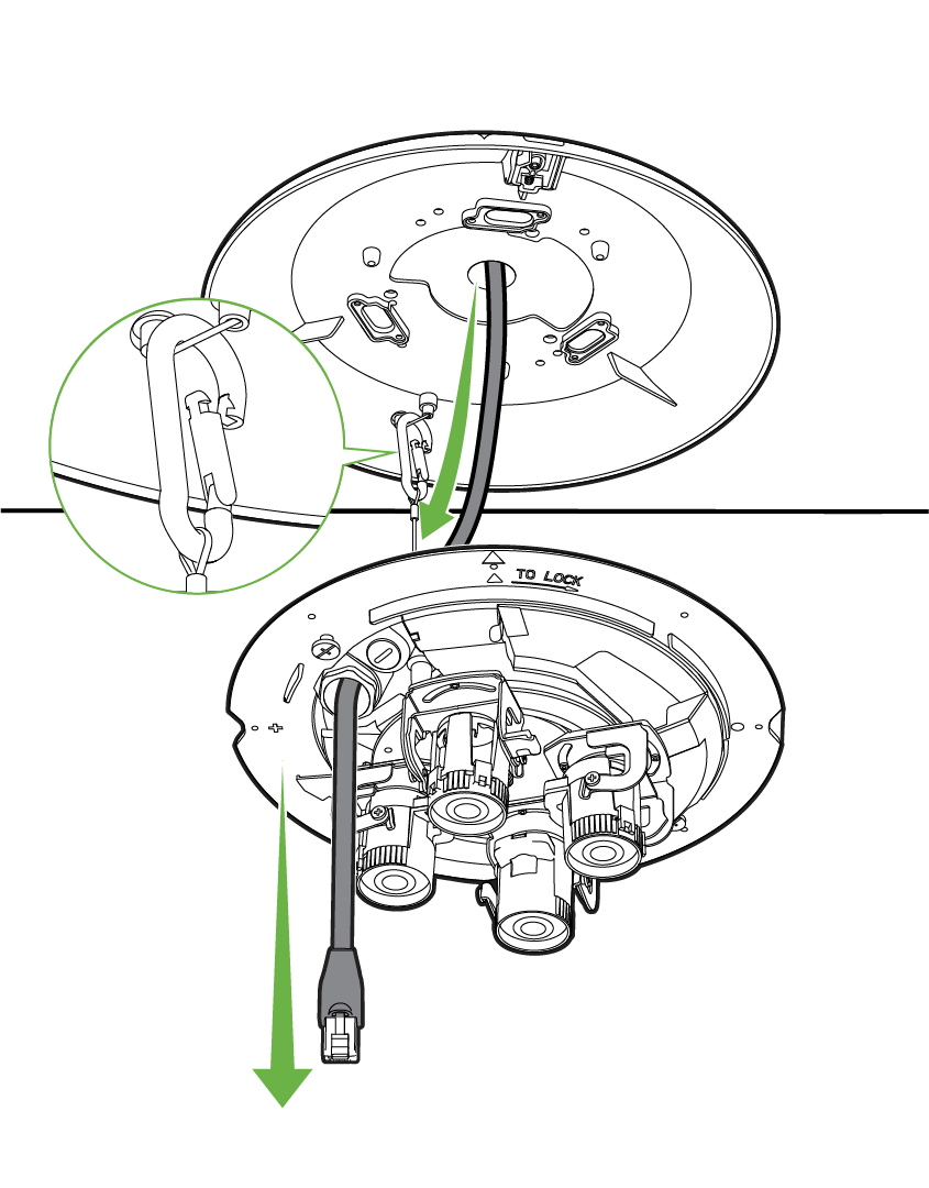
Step 8: Position the Camera Body
-
Hook the support cable on the camera assembly into the built-in clamp on the underside of the mounting plate (highlighted in the inset image).
-
Guide the Ethernet cable through the opening in the camera assembly.
-
Ensure there is enough slack to comfortably reach the camera’s port without stressing the cable.
-
Step 9: Reattach the Camera Assembly

-
Gently lift the camera assembly toward the mounting plate.
-
Keep the network cable centered so it isn’t pinched or twisted.
-
-
Twist the camera assembly in the direction of “TO LOCK” marker to the mounting plate and align the arrow marks to lock the parts together.
-
Ensure the plate and camera assembly seat flush against each other and against the ceiling.
-
Ensure you have approximately 20cm of the network cable dropping down from the camera assembly so that it reaches the ethernet port.
-
Double-check the cable’s path to ensure it is free of sharp edges and not compressed between the plate and the ceiling.
Step 10: Reassemble the Cable Gland

-
Gather the top cap, compression ring, and bottom insert (the parts you removed earlier in Step 6).
-
One by one, guide the components up the cable in the correct order:
-
The bottom rubber gasket.
-
The seal basket.
-
The threaded top cap.
-
-
Reassemble the pieces together as shown in the image.
-
Push the reassembled gland pieces into the camera’s port or housing opening (where the cable emerges).
-
Screw the top cap into place using the wrench provided by rotating it clockwise.
Important: When using the wrench, make sure it does not hit the lens or imager.
Step 11: Power On and Verify Network Connection

-
Align the RJ45 connector with the camera’s Ethernet port.
-
Push it in firmly until you hear or feel the latch click into place.
-
-
Ensure the power source is Type 3 PoE++ (802.3bt).
-
Look for an LED indicator to confirm the camera is powered.
-
Wait for the camera to show online on the Meraki dashboard and ensure the video feed is viewable.
Step 12: Adjust the Camera Angle and Orientation

-
Once the live view is available, the lenses can now be correctly aimed as needed by following these steps:
-
Move the camera imager vertically to capture more ceiling or floor as needed.
-
Rotate the lens horizontally on the 360 track to aim the lenses at the areas of interest.
-
Adjust the lens assembly to straighten the image if the scene appears tilted.
-
Use the Meraki dashboard to Optical Zoom each imager if needed, if you want a narrower field of view.
-
-
Use the Meraki dashboard to verify the camera’s angle is correct.
-
Make fine-tune adjustments until you have the optimal field of view.
After the camera is online for a few minutes, it will begin a firmware upgrade sequence. If this occurs during aiming, wait a few minutes for the video feed to appear after the firmware upgrade.
Step 13: Replace the Desiccant Packets

-
The MV84X ships with pre-installed desiccant packs to ensure the camera is moisture-free during transit and installation, these packs must be removed and replaced with a fresh set of desiccant packs provided in the box.
-
Remove the two desiccant packs and identify the designated spots inside the camera assembly where the desiccant packets should be placed.
-
Find the two new desiccant packs and remove it from its silver colored protective pouch.
-
Handle the packets carefully; avoid tearing or puncturing them.
-
-
Place two desiccant packets into the recommended slots or areas, as indicated by the arrows in the diagram.
Tip: Desiccant helps mitigate condensation, especially in environments with varying temperatures or high humidity. Ensure that you replace them.
Step 14: Reattach the Dome Cover
 |
 |
-
Hold the dome cover (the large outer shell) and position it so the alignment markers match up with the camera assembly.
-
You will see small arrows on the dome and camera base indicating the correct orientation.
-
Ensure the dome edges are flush with the camera’s base, no gaps should be visible.
-
Identify the eight (8) perimeter screws around the dome cover (the same ones loosened in earlier steps).
-
Using the T10 torx security-bit screwdriver, turn each screw clockwise until it’s snug.
-
Tighten them in a star or alternating pattern to ensure even pressure (e.g., top-left, then bottom-right, etc.). Avoid Over-Torquing.
-
Stop once you feel moderate resistance as over-tightening can strip threads.
-
Once fully tightened, the dome should be firmly in place, with no visible gaps.
Step 15: Attach the IR Shield
 |
 |
-
Hold the Infrared (IR) shield below the camera dome, orienting it so the cutout matches the dome’s contours (Cisco logo).
-
Slide or push the shield onto the dome until it seats snugly around the camera housing.
-
You should hear four clicks from the corner of the IR Shield.
-
-
The shield should fit flush against the dome edges, with minimal gaps for optimal IR reflection.
-
If it doesn’t sit evenly, remove and realign.
Tip: The shield directs infrared light correctly at night, and proper installation reduces glare or reflections on the dome.
MV84X LED Status Indicator
Your MV84X is equipped with an LED light on the front of the unit to convey system functionality and performance information.
The following colours and patterns indicate the various status conditions of an MV:
-
Rainbow (solid, rotating through colours) - MV is booting up.
-
Flashing Green - MV is upgrading or initialising for the first time.
-
Solid Green - MV is connected via Ethernet.
-
Solid Amber - MV is not able to connect to the Dashboard.
