
MV84X Mounting Options and Guidelines
Summary of Mounting Options
Here is the complete list of mounting accessories available for the Cisco Meraki MV84X.
| SKU | Use Case |
|---|---|
| MA-MNT-MV-19: Pendant Head MA-MNT-MV-29: Pendant Pipe (20 cm) (1.5” PS11) MA-MNT-MV-39: Mounting Adapter for Pendant/Parapet |
Pendant Installation: You will require these mounting accessories for a Pendant style install. |
| MA-MNT-MV-49: Wall Mount Bracket | Wall Arm Mounting |
| MA-MNT-MV-59: Junction Box |
Junction Box: Incorporate a Junction box if you cannot flush the camera to the ceiling or flush a mount to the wall. |
| MA-MNT-MV-69: Pole Mount Adapter | Pole Mount Installation |
| MA-MNT-MV-79: Corner Mount Adapter |
Corner Mount Installation: You will require a MA-MNT-MV-49 to go with this mount to ensure the camera is facing downwards when the installation is completed. |
| MA-MNT-MV-89: Parapet Mounting Bracket | Parapet Installation |
Mounting Guidelines
-
Use the table above to choose your camera placement and identify the accessories you need.
-
Decide if your installation requires a Junction Box.
-
-
Use an 802.3bt power source to set up your camera.
Specific Recommendations
Find a complete set of drawings for all mount plates and mounts in the accessories section below. Access ordering information and technical specifications on the Cisco Meraki website.
Installation Types
Pendant Mount Installation Guide
Overview
.png?revision=1&size=bestfit&width=600&height=336)
A pendant mount is an overhead mounting solution for suspending a camera from a ceiling or overhang. It provides a flexible viewing angle and makes cable management easier. In retail settings with four-way foot traffic and high ceilings, a pendant mount is useful for unobstructed coverage, ensuring the camera captures critical areas without being blocked by shelving or fixtures. This guide explains how to install the MV84X camera using accessories MA-MNT-MV-19, MA-MNT-MV-29, and MA-MNT-MV-39 for a secure, professional finish.
This guide explains how to install the MV84X camera with a pendant mount on a ceiling (or overhead surface). The steps include:
1. Selecting a suitable mounting location.
2. Preparing holes for the mount.
3. Routing cables through the pendant.
4. Securing anchors and fastening the mount.
5. Attaching and adjusting the camera.
Follow local building codes and safety practices. Consult a professional installer if you are unsure.
What’s in the box?
| SKU | Item | Specifications | Quantity |
|---|---|---|---|
| MA-MNT-MV-19 | Pendant Head | - | 1 |
| L-Shaped Wrench | 58x20 mm; 3mm Hex | 1 | |
| MA-MNT-MV-29 | Pendant Pipe | 20 cm | 1 |
| L-Shaped Wrench | 58x20 mm; 3mm Hex | 1 | |
| MA-MNT-MV-39 | Mounting Adaptor for Pendant/Parapet | - | 1 |
Step 1: Position and Mark the Mounting Plate
%25404x.png?revision=1&size=bestfit&width=618&height=535)
-
Choose the Ceiling Location
-
Determine where you want to install the pendant mount. Make sure the ceiling can support the weight of the camera and mount.
-
-
Alignment sticker for Pendant Base
-
Hold the Pendant base alignment sticker provided against the ceiling in the exact spot where you intend to install the camera.
-
Align any cable pass-through holes with the point where your cable will emerge from the ceiling.
-
-
Drill the Holes
-
Select the drill bit size recommended for your anchors or mounting hardware.
-
Carefully drill the pilot holes at the marked locations, keeping the drill bit straight.
-
Remove any debris or dust from the holes so the anchors and screws will seat properly later.
-
Step 2: Insert Anchors and Route the Cable
%25404x.png?revision=1&size=bestfit&width=613&height=545)
-
Insert the Anchors
-
If your ceiling material requires anchors (e.g., drywall or concrete), gently tap each anchor into the drilled holes using a hammer.
-
Make sure they’re flush with the ceiling surface and firmly seated
-
-
Feed the Cable
-
Pass your Ethernet cable through the center hole (or conduit) in the ceiling so it can emerge below where the mount will attach.
-
Ensure there is enough slack on the camera end for easy connection later.
-
Step 3: Install the Pendant Head
%25404x.png?revision=1&size=bestfit&width=625&height=567)
-
Align the Pendant Head
-
Position the MA-MNT-MV-19 head (the circular component) against the ceiling so its screw holes line up with the anchors you installed in Step 2.
-
If using conduit, confirm the conduit port on the pendant head is oriented in the desired direction.
-
-
Feed the Cable (if not already done)
-
Pull the Ethernet cable through the center opening of the pendant head.
-
Ensure you have enough slack below the head to connect to the camera later.
-
-
Insert and Tighten Screws
-
Secure the pendant head to the ceiling by threading the provided screws (or the hardware recommended for your ceiling type) into the anchors.
-
Step 4: Attach the Pendant Pipe
%25404x.png?revision=1&size=bestfit&width=665&height=640)
-
Thread the Pendant Pipe onto the Pendant Head
-
Align the 1.5” (PS11) threaded end of the MA-MNT-MV-29 Pendant pipe with the pendant head’s corresponding threads.
-
Gently rotate the pipe clockwise until it is fully seated.
-
-
Tighten the security screw
-
Use the included Allen (hex) wrench to tighten the security screw as shown in the image.
-
Step 5: Install the Mounting Adapter
%25404x.png?revision=1&size=bestfit&width=676&height=655)
-
Position the Adapter
-
Slide the MA-MNT-MV-39 adapter (the circular plate with a central opening) over the cable and up toward the bottom of the pendant pipe.
-
Align its threaded collar with the pipe’s inner threads.
-
-
Thread the Adapter Onto the Pipe
-
Gently rotate the adapter clockwise (see label 1 in the illustration) until it is fully seated against the pipe.
-
-
Tighten the Set Screw
-
Locate the small security screw on the side of the adapter (label 2 in the diagram).
-
Using the included Allen (hex) wrench, turn the screw until it’s snug
-
Step 6: Install the MV84X
-
Once the pendant mount is ready, align the MV84X’s base plate to the mounting adapter on the pendant mount.
-
Screw in the base plate and continue with the MV84X install as shown here.
Wall Arm Mount Installation Guide
Overview
.png?revision=1&size=bestfit&width=712&height=400)
A wall arm mount extends the camera outward and downward from a vertical surface, letting you achieve a clear, downward-facing view even when mounting on the side of a wall. This guide explains how to install the MV84X using the MA-MNT-MV-49 bracket, ensuring a secure and streamlined setup.
What’s in the box?
| SKU | Item | Specification | Quantity |
|---|---|---|---|
| MA-MNT-MV-49 | Wall Mount Bracket | 1 | |
| Expansion Screw | 10x76 mm | 4 | |
| Flat Washer | 19 mm | 4 | |
| M6x15 screw | 3 | ||
| Flat Washer | 13 mm | 3 | |
| Spring Washer | 10.5 mm | 3 |
Step 1: Position the Wall Mount Alignment sticker
 |
 |
-
Select the Mounting Location
-
Identify a suitable area on the wall that provides a clear field of view for the camera.
-
Verify the wall can support the combined weight of the bracket and camera.
-
-
Align the Bracket
-
Hold the alignment sticker flush against the wall where you want the camera to be installed and make a note of the pilot holes and the cable cutout.
-
-
Drill Pilot Holes
-
Use a 9.5 mm (3/8 inch) drill bit (or as recommended for your specific anchors).
-
Drill pilot holes at the marked locations to the recommended depth.
-
Remove any debris or dust from the holes.
-
Step 2: Insert the Expansion Screws
 |
 |
-
Insert the Expansion Screws
-
Take each 10×76 mm Expansion Screws and push (or gently tap) it into the corresponding hole until it is flush with the wall surface.
-
-
Ensure Proper Fit
-
Verify that each expansion screw sits snugly in the hole and that the bracket holes line up correctly.
-
The anchor sleeves should remain in the wall, ready for final tightening in the next step.
-
-
Remove the nut and the washer from the anchor as shown in the image, and keep them aside safely for a later stage of the installation.
Step 3: Route the Cable and Install Wall Arm Mount
 |
 |
 |
-
Locate the Wall Opening
-
Identify the center hole you drilled (or existing hole) where the camera’s Ethernet cable will pass through.
-
-
Feed the Cable
-
Gently push or pull the cable from the interior side of the wall so it exits on the exterior side (where the bracket will be).
-
-
Insert the Cable
-
Thread the cable through the opening in the wall mount bracket
-
Pull it through until you have enough cable length on the bracket’s exterior side to reach the camera’s ethernet port.
-
-
Align Bracket with Anchors
-
Slide the bracket over the previously installed anchor bolts (from Step 2).
-
Check that the bracket’s mounting holes line up correctly with each bolt.
-
-
Add Washers and Nuts
-
Place the provided washers over the bolt ends, then thread on the nuts by hand.
-
Tighten each nut using a wrench or socket, applying an even, diagonal pattern to pull the bracket flush against the wall.
-
Step 4: Install the MV84X on the Wall Arm Mount
-
Once the Wall Arm Mount is installed on the wall, align the MV84X’s base plate to the mounting adapter on the pendant mount.
-
Screw in the base plate and continue with the MV84X install as shown here.
Junction Box Installation Guide
Overview
A junction box mount provides a secure enclosure for protecting cables and connections behind or above a camera or other device. It helps conceal wiring, maintain a clean look, and offer convenient access to power or network lines. In this guide, you’ll learn the basic steps to install a junction box mount for your MV84X, keeping cables organized and shielded from the elements.
Whats in the box?
| SKU | Item | Specification | Quantity |
|---|---|---|---|
| MA-MNT-MV-59 | Junction Box | 255x199 mm | 1 |
| M8x20 hex screw | 4 | ||
| M8x30 hex screw | 3 | ||
| M8 nylon nut | 4 | ||
| M8 spring washer | 4 | ||
| M8 flat washer | 4 | ||
| T25 wrench | 1 |
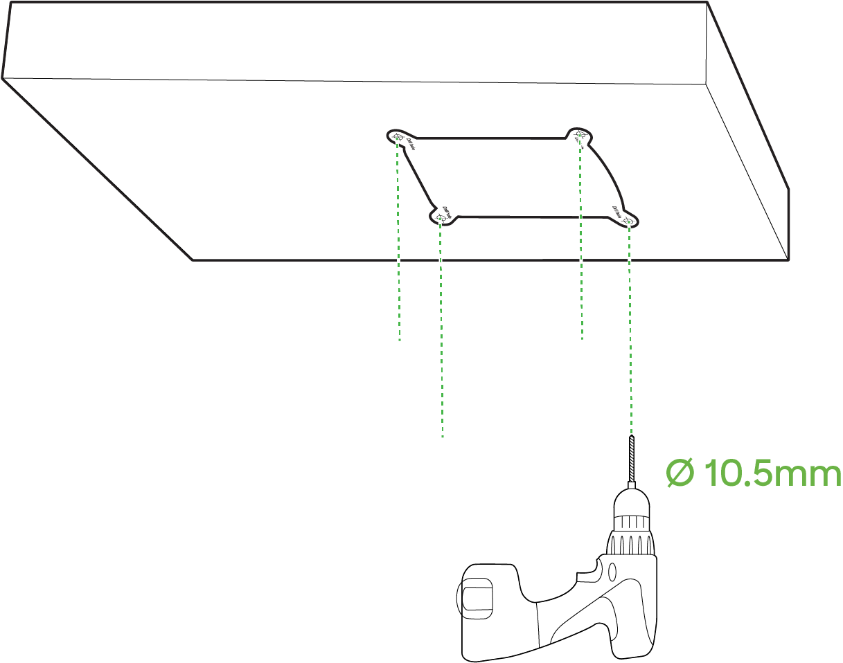
Step 1: Position the Alignment Sticker
 |
 |
-
Select the Mounting Location
-
Identify a suitable area on the wall that provides a clear field of view for the camera.
-
Verify the wall can support the combined weight of the bracket and camera.
-
-
Align the Bracket
-
Hold the alignment sticker flush against the wall where you want the camera to be installed and make a note of the pilot holes and the cable cutout.
-
-
Drill Pilot Holes
-
Use a 10.5mm drill bit (or as recommended for your specific anchors).
-
Drill pilot holes at the marked locations to the recommended depth.
-
Remove any debris or dust from the holes.
-
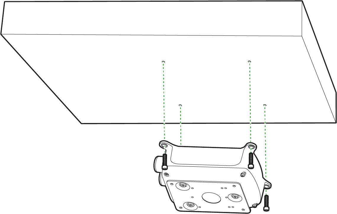
Step 2: Mount the Junction Box to the Ceiling
 |
 |
-
Position and install the box
-
Align the junction box (MA-MNT-MV-59) with the pilot holes or marked positions from earlier steps.
-
Secure the junction box to the ceiling using the recommended screws (and anchors, if needed).
-
Tighten each screw evenly in a diagonal pattern to pull the box snug against the surface.
-
-
Attach the Camera Mounting Plate
-
Carefully pull the camera’s Ethernet/power cable through the junction box opening and out the bottom center hole.
-
Position the camera’s base plate against the bottom of the junction box.
-
Fasten the mounting plate to the junction box using the supplied screws.
-
Tighten them in an alternating pattern to ensure an even, secure fit.
-
Step 3: Install the MV84X on the Wall Arm Mount
-
Once the Junction box is installed on the ceiling and the base plate is attached to it, continue with the MV84X install as shown here.
Corner with Wall Arm Mount Installation Guide
Overview
.png?revision=1&size=bestfit&width=668&height=375)
A corner mount allows you to place a camera on the corner edge of a building or wall, granting a wide angle of coverage on two adjoining sides. It’s especially useful for monitoring adjacent walls, corridors, or outdoor corners with minimal blind spots. This guide explains how to install the MV84X camera using the corner mount bracket for secure, effective surveillance.
What is in the box?
|
SKU |
Item |
Quantity |
|---|---|---|
| MA-MNT-MV-79 | Corner Mount | 1 |
| M8x16 hex screw | 4 | |
| M8x35 hex screw | 4 | |
| M4x16 hex screw | 4 | |
| M8 nut | 6 | |
| M8 spring washer | 4 | |
| M8 flat washer | 6 | |
| M4 nut | 4 | |
| M4 spring washer | 4 | |
| M4 flat washer | 4 |
Step 1: Assemble and Secure the Corner Mount Bracket
%25404x.png?revision=1&size=bestfit&width=298&height=370)
-
Orient and assemble Bracket Panels
-
Align the corner mount bracket so its panels have the pre-drilled holes lined up to continue the full assemble
-
Once the bracket’s side flanges or overlapping plates are aligned, insert each bolt through the matching holes from outside to the inside of the bracket, ensuring they pass cleanly through both metal layers.
-
-
Tighten the nuts from the Inside
-
From the inside of the bracket (the side facing the corner), thread and hand-tighten the nuts onto each bolt.
-
Confirm that both panels meet smoothly at the corner without gaps.
-
Step 2: Attach the bracket to the desired corner
-
Position the bracket to drill pilot holes
-
Hold the corner mount bracket against the building’s corner, ensuring the panels meet flush with both adjoining walls.
-
While keeping the bracket level and in the correct vertical position, mark each of the bracket’s mounting hole locations on both wall surfaces.
-
Select the appropriate drill bit size for your anchors or mounting bolts and drill pilot holes at each marked spot, removing any debris afterward.
-
For hollow walls (e.g., drywall) or solid masonry, tap the recommended anchors into the pilot holes until they are flush. Make sure the wall can support the weight of the camera and mounting hardware.
-
Fasten the Bracket
-
Place the bracket back against the corner, aligning the mounting holes with your newly installed anchors or pilot holes.
-
Insert and thread the mounting bolts or screws, tightening them evenly in a diagonal or alternating pattern.
-
Avoid over tightening; stop once the bracket is secure and doesn’t shift.
-
Step 3: Attach the Mount Arm to the Corner Brackets
%25404x.png?revision=1&size=bestfit&width=586&height=492)
-
Feed the Cable and Align the Wall Arm
-
Guide the Ethernet cable through the cable opening in the corner bracket.
-
Pull enough slack through so you can easily connect it to the camera’s port.
-
-
Position the camera’s wall arm (MA-MNT-MV-49) against the corner bracket’s bolt holes.
-
- Insert Mounting Bolts
- Using the provided hardware, thread each bolt through the bracket into the arm’s mounting plate
- Start each bolt by hand to avoid cross-threading.
- Use a wrench or driver to snug each bolt, applying balanced pressure in a diagonal or alternating pattern.
Step 4: Install the MV84X on the Wall Arm Mount
-
Once the Corner brackets and Wall Arm is installed and the base plate is attached to it, continue with the MV84X install as shown here.
Parapet Mount Installation Guide
Overview
.png?revision=1&size=bestfit&width=716&height=402)
A parapet mount is designed for installing a camera on the edge of a rooftop or elevated structure, allowing it to extend safely over the building’s parapet. This setup offers a clear, downward-facing view while keeping critical roof space unobstructed. In this guide, you’ll learn how to mount the MV84X using a parapet bracket for secure, high-angle surveillance coverage.
What's in the box?
| SKU | Item | Quantity |
|---|---|---|
| MA-MNT-MV-89 | Parapet Mounting Bracket | 1 |
| Flat wall fixed plate | 3 | |
| Bottom fixed plate | 1 | |
| Pipe fixed plate | 3 | |
| Corner wall fixed plate | 3 | |
| Expansion screw | 6 | |
| M8x70 screw | 3 | |
| M8x25 screw | 6 | |
| L shaped wrench | 1 | |
| Flat wall alignment sticker | 1 | |
| Corner wall alignment sticker | 1 |
Step 1: Drill Pilot holes; Secure anchors, washers and nuts on the parapet
 |
 |
 |
-
Choose the Parapet Location and drill the Pilot Holes
-
Determine the exact spot on the parapet or rooftop ledge where the mount will be placed.
-
Ensure there’s enough clearance above and below for the mount and any cables.
-
Hold the Flat wall alignment sticker template (provided) against the parapet, making sure it’s level and oriented correctly.
-
Use a pencil or marker to note the positions of each required bolt hole.
-
-
Carefully drill pilot holes straight into each marked location.
-
-
Insert the expansion screws
-
Gently tap each expansion screw (6) into its pilot hole using a hammer.
-
Stop once the anchor is flush with the parapet surface
-
Remove the nut and the washer from the expansion screw as shown in the image (3), and keep them aside safely for a later stage of the installation.
-
Step 2: Install the Fixed Plates
 |
 |
- Align the Flat wall Fixed Plates with the Parapet
- Hold each plate against the parapet, spacing them 65 mm (2.55”) apart (or per your design requirement).
- Thread the nuts and washers on from the backside.
- Install the Pipe fixed plate on to the flat wall fixed plate
- Use the provided screws to LOOSELY tighten the pipe plate on to the flat wall fixed plate
Step 3: Install the Parapet Arm and route the cable through it

- Attach the Mounting adapter to Parapet Arm
- Install the mounting adapter (MA-MNT-MV-39) to the end of the parapet arm where the MV84X will be installed
- Tighten the security security screws to secure the mounting adapter to the parapet arm.
- Route the Ethernet cable through the parapet arm and route it out through the mounting adapter
- Lift the parapet arm (with cables routed) and line it up with the pipe plates on the parapet bracket.
- Slide the arm’s lower end over the mounting assembly
Step 4: Mount and Orient the Parapet Arm

-
Rotate the Arm to Desired Angle
- Gently rotate or pivot the arm until it’s in the ideal position for your use case.
-
Secure the Final Orientation
-
Once satisfied with the angle, use a wrench to fully tighten the bolt or clamp.
-
Step 5: Install the MV84X on the Parapet Mount
-
Once the parapet mount is installed, continue with the MV84X install as shown here.
Pole Mount Installation Guide
Overview
.png?revision=1&size=bestfit&width=670&height=376)
A pole mount securely attaches a camera to a pole, providing visibility in locations where wall or ceiling mounting isn’t feasible. It’s ideal for outdoor areas, parking lots, and locations lacking a flat mounting surface. In this guide, you’ll learn how to install the MV84X camera using the Pole Mount (MA-MNT-MV-69), the Wall Mount (MA-MNT-MV-49) and an optional Junction box (MA-MNT-MV-59) for a stable, elevated view.
What's in the box?
| SKU | Item | Quantity |
|---|---|---|
| MA-MNT-MV-69 | Pole Mount Adapter | 1 |
| Stainless ring | 3 | |
| M8x16 hex screw | 4 | |
| M8x35 hex screw | 4 | |
| M4x16 hex screw | 4 | |
| M8 nut | 6 | |
| M8 spring washer | 4 | |
| M8 flat washer | 6 | |
| M4 nut | 4 | |
| M4 spring washer | 4 | |
| M4 flat washer | 4 |
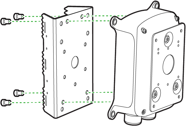
Step 1: Prepare the Pole Mount Adapter for the install
-
If using a Junction box: Position the Pole mount adapter against the back of the junction box (MA-MNT-MV-59)
- Line up the pre-drilled holes in the Pole mount adapter with the corresponding holes on the Junction box.
-
Insert and Tighten Screws
-
Feed the hex screws through the back of the pole mount adapter into the junction box.
-
Tighten with the washers and nuts in a cross or alternating pattern to ensure the adapter is flush and secure.
-
Ignore these steps if a junction box is not utilized for your install.
Step 2: Mount the Pole Adapter to the Pole

-
Wrap the Stainless Rings (Hose Clamps)
-
Take each stainless ring and pass it around the pole at the desired height.
-
Thread the free end into the clamp housing to form a loop.
-
-
Position the Pole Adapter
-
Align the adapter assembly (with the optional junction box ) against the pole so the stainless rings line up with the slots on the adapter’s sides.
-
-
Tighten the Clamps
-
Using a flathead or socket driver, turn the clamp bolt clockwise to tighten each ring.
- Ensure the bracket is vertical and the camera mounting side is facing your target viewing area.
-
Step 3: Attach the Wall Mount to the Pole Mount Assembly

-
Route the cable through the pole adapter
-
Feed the Ethernet cable through the bracket’s center
-
Ensure you have enough slack on both the camera and pole sides.
-
-
Complete the Wall Arm install
-
Hold the wall arm mount (MA-MNT-MV-49) against the adapter (or junction box) and route the cable through the wall arm mount.
-
Match up the bolt holes so the arm is oriented for the proper field of view.
-
Use the screws, nuts, and washers to secure the wall arm mount to the pole adapter (or junction box)
-
Step 4: Install the MV84X on the Wall Arm Mount
-
Once the Pole mount brackets and Wall Arm is installed, continue with the MV84X install as shown here.