
MV93 Installation Guide
MV93 Series Overview
The Cisco Meraki MV93 series are third-generation network cameras. They are easy to deploy and configure because they integrate with the Meraki Dashboard and use cloud-augmented edge storage. The MV series removes the need for complex servers and video recorders used in traditional systems. This eliminates limits on video surveillance deployments.
Package Contents
In addition to the MV camera, the following are provided:


|
Unit |
MV93-HW MV93M-HW MV93X-HW |
|---|---|
|
Mounting Equipment |
1 x base mount plate small 1x base mount plate large 1x Decorative cover 1 x conduit adapter 1 x Allen Wrench |
MV93 series does not ship with mounting screws and anchors as an included accessory in the packaging content.
Screw Recommendation:
- Type: Self-Tapping Screw
- Size: M4
- Length: Minimum 25mm
- Screw head diameter: Maximum 10mm
- Driver Type: ANY (eg: Philips)
- Head Type: ANY (Eg: Pan Head)
- Build Material: Stainless Steel
The anchor's insertion diameter should be smaller than the screw's diameter, and the anchor's length should be longer than the screw's length. Choose the appropriate anchor based on the material where it will be installed, such as concrete, brick, wood, or drywall.
Powering the MV93 Series
The MV93 features a 1000BASE-TX Ethernet port and requires 802.3at PoE+ minimally for operation. Route the Ethernet cable from an active port on a PoE switch or injector.
Power over Ethernet supports a maximum cable length of 300 ft (100 m).
Placement Guidelines
The Meraki MV93 is a fisheye camera boasting a full 360 degree field-of-view of the area underneath the camera. The resulting camera image provides an expansive view of its nearby surroundings. This becomes extremely useful when you want to capture an overview of your entire scene and can take the place of multiple cameras. To ensure you have sufficient camera coverage for your specific use case, the placement guidelines for MV93 are outlined along with expected coverage quality.
You can change between different viewing options on the MV93.

Initial Considerations
The MV93 gives you a wide view of the area to help you understand the situation. However, it does not fully replace other cameras in your surveillance system. First, identify the goals you want to achieve with your new fisheye camera. Ask yourself these questions:
-
What level of detail do you require from your image?
-
What distance from the camera’s center is this level of detail required?
-
Are there any restrictions around mounting cameras to walls and/or ceilings?
We recommend utilizing the fisheye camera to detect an event of interest, and a fixed lens or varifocal camera to identify key details for further action. For example, if placing an MV93 in the center of a room, an MV12 or MV22 camera that is placed facing key points of entry will provide you the level of detail in the event that person identification is required.
General Guidelines
To maximize the coverage of your MV93, the right placement and positioning is essential. The following tips and guidelines should be considered when positioning your MV93:
- Mount the camera 10 - 14 ft (3 - 4.3 m) above the ground to optimize for object detail within 20 ft (6.1m) of the surrounding area. At this height, the on-board analytics can detect objects within a radius of up to 25 ft (7.6 m) from the camera’s center.
Note: If your surface is very high, you can use the Telescoping Pendant Mount to lower the mounting height of the camera.
- Position your camera away from corners to fully utilize its 360 degree FoV. The ideal placement is typically on the ceiling at or near the center of a room.
- Keep ambient lighting consistent. With a larger FoV, it can be difficult to maintain consistent lighting conditions throughout the entire frame. Two areas of drastically different lux levels will impact the quality of your video stream. Monitor your camera’s visibility during installation to determine if additional light sources are required to capture the entire scene. Avoid placing cameras where light sources are pointed directly at the camera dome, as this can cause degradation of image quality.
Coverage Guidelines
At the recommended height of 10-14 feet off the ground, the level of detail which can be captured from the camera is represented below. The following screenshots will give you an idea of the level of detail you can expect to see from certain distances away from the center of the camera. The subject is 5 ft 9 in (171 cm) tall and holding a sign with text that is 1-2 inches tall and the camera is mounted 9ft off the ground. ( All images captured at highest quality available on MV93). The images attached below are unedited but taken is dewarped view.
-
0 to 10 feet: At this distance, detailed images can be captured which allow identification of an object or person. Facial details can be discerned and small objects can be identified.

 Highest Quality ( 2880x2880, Enhanced) High retention ( 1080p, High)
-
10 to 20 feet: At this distance, object and person identification is still possible, however some details will be lost.

 Highest Quality ( 2880x2880, Enhanced) High retention ( 1080p, High)
-
20 to 40 feet: At this distance, details will be lost and identification of objects or people is possible but will become difficult. Smaller objects may become invisible if a lower resolution is selected. If identification is needed at these distances, consider supplementing your camera design with additional cameras.

 Highest Quality ( 2880x2880, Enhanced) High retention ( 1080p, High)
Understanding the amount of detail required at a specific radius extending from your fisheye camera will allow proper planning and design of your security camera system. Use the reference PPF values in this KB for exact calculation.
Frequently Asked Questions
Can I mount the MV93 on the wall?
If mounted on a wall, half of the camera’s field of view will face the adjacent ceiling. This setup does not fully utilize the MV93’s 360-degree field of view. The MV93 works better when installed on a ceiling, where more of the field of view captures useful content. The digital pan-tilt-zoom (DPTZ) feature lets you choose the mounting position, making panning feel more natural.

 Highest Quality ( 2880x2880, Enhanced) High retention ( 1080p, High)
The camera’s computer vision analytics rely on training algorithms using a top-down view of the surroundings. Installing the MV93 at any angle other than this reduces the analytics’ effectiveness. Do not install the MV93 perpendicular to the ground.
What happens if I place the camera on a surface higher than the recommended 10-14 ft?
Mounting the MV93 higher than the recommended maximum height of 14 feet will result in decreased image quality of the surrounding area and impact the performance of the built-in people detection analytics. Placement at this height will enable an overview of larger areas but impact the amount of recognizable detail in the image. If your surface is very high, you can use the Telescoping Pendant Mount to lower the mounting height of the camera.
Can I replace all my cameras with a single MV93?
The MV93 is a great option to deploy if you desire a broad overview of the scene and to gain situational awareness. In general, we recommend utilizing the fisheye camera to detect an event of interest, and a fixed lens or varifocal camera to identify key details of the scene.
Pre-Install Preparation
You should complete the following steps before going on-site to perform an installation:
Configure Your Network in the Dashboard
The following is a brief overview of the steps required to add an MV93 series camera to your network. For detailed instructions about creating, configuring and managing Meraki Camera networks, refer to the online documentation (https://documentation.meraki.com/MV).
-
Login to https://dashboard.meraki.com. If this is your first time, create a new account.
-
Find the network to which you plan to add your cameras or create a new network.
-
Add your cameras to your network. You will need your Meraki order number (found on your invoice) or the serial number of each camera, which looks like Qxxx-xxxx-xxxx, and is found on the bottom of the unit.
-
Verify that the camera is now listed under Cameras > Monitor > Cameras.
Check and Configure Firewall Settings
If a firewall is in place, it must allow outgoing connections on particular ports to IP addresses. The most current list of outbound ports and IP addresses for your organization can be found under Help>Firewall Info on the dashboard.
DNS Configuration Best practices for LAN Streaming
Each camera will generate a unique domain name for secured direct streaming functionality. These domain names resolve an A record for the private IP address of the camera. Any public recursive DNS server will resolve this domain.
If utilizing an on-site DNS server, please allow *.devices.meraki.direct or configure a conditional forwarder so that local domains are not appended to *.devices.meraki.direct and that these domain requests are forwarded to Google public DNS.
Assigning IP Addresses
Currently, the MV93 series camera does not support static IP assignment. MV93 units must be added to a subnet that uses DHCP and has available DHCP addresses to operate correctly.
Installation Instructions
During first-time setup, the MV93 series will automatically update to the latest stable firmware. Some features may be unavailable until this automatic update is completed. This process may take up to 5 minutes to enable whole disk encryption. The state of this process can be monitored by referencing the MV LED Status.
The MV93 body can become very hot during operation and must be handled carefully.
Mounting Instructions
The MV93 wall mount offers a fast, easy, and flexible way to install your device in most mounting situations. Follow a few simple steps to complete the installation.
Leave the protective plastic cover on the optical dome throughout the installation process to prevent any damage to the dome. The protective cover should be removed once the installation process is completed.

Microphone Cut-off Switch
The MV93 Series has a new microphone cut-off switch at the camera's base. This switch can be used to disable audio and override the Dashboard Audio Settings for an added layer of security. If the regulations require disabling audio or Dashboard control for Audio enablement needs to be disabled, the microphone cut-off switch can be leveraged and set to Disabled.
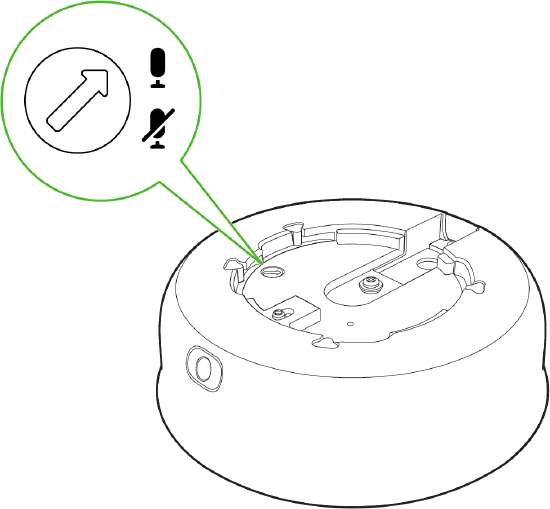
If the microphone switch is disabled and the camera is mounted, toggling the switch back ON would require accessing the camera's base.
Factory Reset Button
The factory reset button for MV93 series is located on the back of the camera.

Mounting Base Plate Template Instructions
Use the template to determine mounting hole locations for wall mounting before screwing in the base mount plate. Peel backing from the mounting template to stick on the wall. Use template holes marked with the letter “A” for standard wall mounting. Screw the base mount plate onto the wall in pre-determined locations using the provided wall screws.


Cable Gland Assembly and Installation
Follow this in-depth cable gland assembly guide to connect the PoE cable to the camera cable gland and ensure seal is water-tight. This step is very important and may result in damage to the camera if done improperly.
If installing external conduit terminated at the camera, ensure the camera conduit adapter and terminal adapter are pulled over the camera pigtail before making the connection to avoid the risk of water damage leading to hardware failure and warranty void.

Conduit Adapter Installation
If using a conduit adapter, attach the terminal adapter to the conduit adapter. Route the conduit over the water-tight cable gland assembly and terminate at the terminal adapter. Ensure the camera conduit adapter is securely placed on the base mount plate as pictured.

Installing the conduit box to MV93 series: (optional)

Attaching to the Mounting Plate
The MV93 series comes with two base mount plates, a small plate and a large plate. The functionality of both plates is identical. Please refer to the guidelines below on using the base plate mounting to any surface or on top of a mounting accessory.
MV93 Mount using small base plate


-
Mount the small base plate onto the wall surface using the paper template provided.
-
Use 3x Wall anchor and screws to fix the base plate to the wall.
-
The MV93 Series cameras have a button to engage the locking mechanism. Press the button while aligning the MV93 series to the small base plate.


-
Twist the camera while holding the button until a click is heard.
-
The camera is locked onto the plate and secured.
-
Use the included Allen wrench to tighten the security screw as needed
MV93 Mount using large base plate


-
Mount the large base plate onto the wall surface using the paper template provided.
-
Use 4x Wall anchor and screws to fix the base plate to the wall.
-
The MV93 Series cameras have a button to engage the locking mechanism. Press the button while aligning the MV93 series to the large base plate.


-
Twist the camera while holding the button until a click is heard.
-
The camera is locked onto the plate and secured.
MV93 Mount using large base plate and Decorative Cover


-
Mount the large base plate onto the wall surface using the paper template provided.
-
Use 4x Wall anchor and screws to fix the base plate to the wall.
-
Place the decorative cover on top of the large base plate and press the cover against the plate. You will hear a click as the decorative cover is secured.

-
The MV93 series cameras have a button to engage the locking mechanism. Press the button while aligning the MV93 series to the small base plate.
-
Twist the camera while holding the button until a click is heard.

- The camera is locked onto the plate and secured.
4. Once completed, twist and lock the camera to the base plate. A click is heard when the camera is locked in place.
Remove the protective cover when the installation is complete.
5. Observe the status LED on the left side of the camera lens assembly and ensure the camera is connected via Ethernet (solid green) or WiFi (solid blue). An MV must first be provisioned over a wired Ethernet connection before it can be deployed wirelessly. See the setup guide here for information on how to connect via WiFi.
MV93 LED Status Indicator
Your MV93 series is equipped with an LED light on the front of the unit to convey system functionality and performance information.
The following colours and patterns indicate the various status conditions of an MV:
-
Rainbow (solid, rotating through colours) - MV is booting up.
-
Flashing Blue - MV is searching for WiFi network(s).
-
Flashing Green - MV is upgrading or initialising for the first time.
-
Solid Green - MV is connected via Ethernet.
-
Solid Blue - MV is connected via WiFi.
-
Solid Violet - MV has audio recording enabled.
-
Solid Amber - MV is not able to connect to the Dashboard.
-
Flashing Red: The MV has detected insufficient PoE power.

Flashing Red LED state: MV5.5 is the minimum firmware requirement for this new state
The MV93 series requires an 802.3at power source; if insufficient power is detected, the MV alerts using a flashing RED LED state and reports more details to the event log.