Configuring VLANs on the MX Security Appliance
As a network grows to include users in multiple physical locations it becomes necessary to segment the network into various virtual networks or VLANs. This article describes how to configure VLANs on the WAN Appliance.
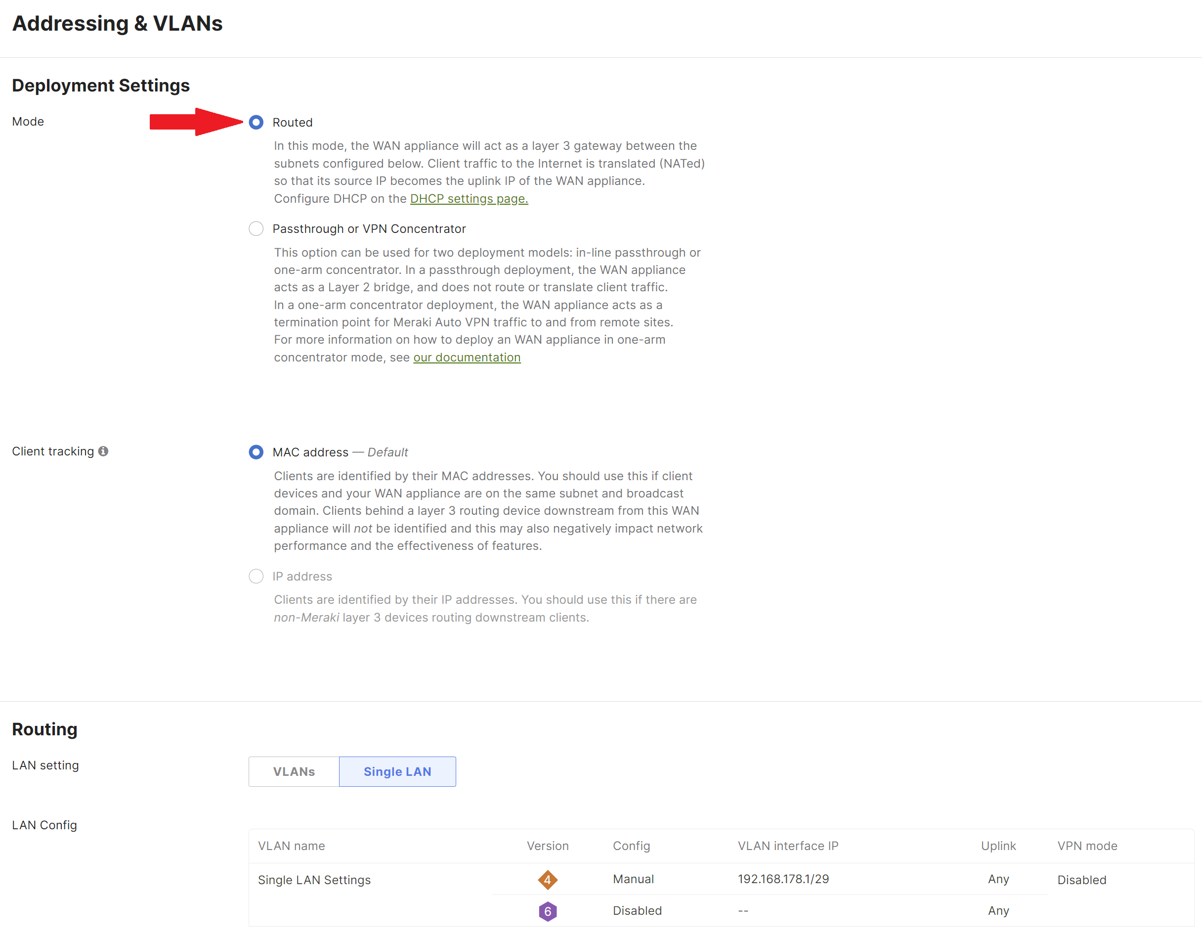
Ensure that the WAN appliance is configured to be in Routed mode on the Security & SD-WAN > Configure > Addressing & VLANs > Deployment Settings > Mode section. VLANs cannot be configured if the WAN appliance is in Passthrough or VPN Concentrator mode.
Enable VLANs on the Dashboard
VLANs are disabled by default on the WAN appliance. They can be enabled from Security & SD-WAN > Configure > Addressing & VLANs > Routing by selecting VLANs.
Note: When VLANs are enabled on a WAN appliance, any DHCP settings that were configured while VLANs were disabled will be deleted. Also, if BGP is enabled on the MX and a change is made from Single LAN to VLANs (and vice versa), this will cause BGP to revert back to disabled state.

Configure VLANs
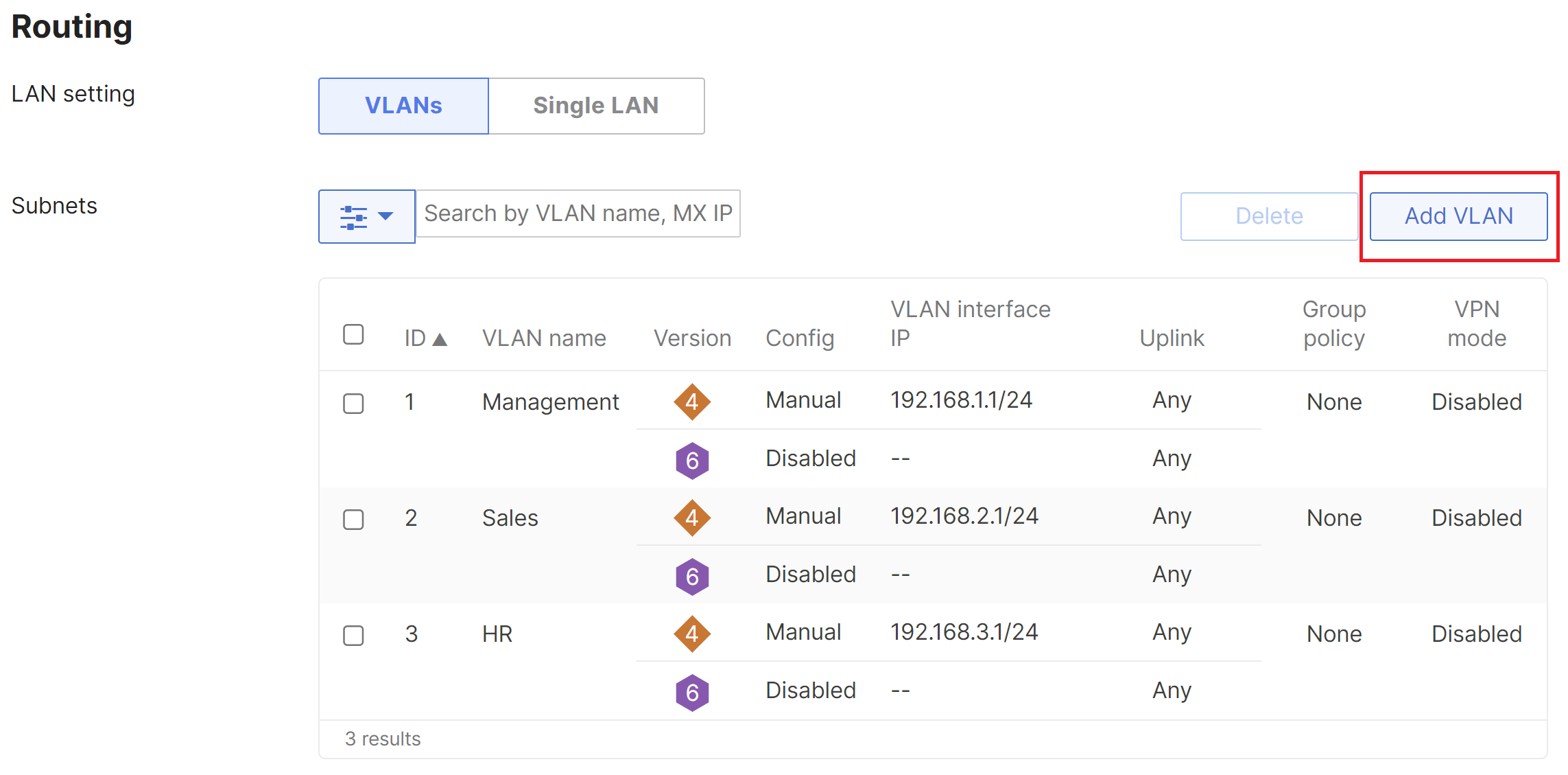
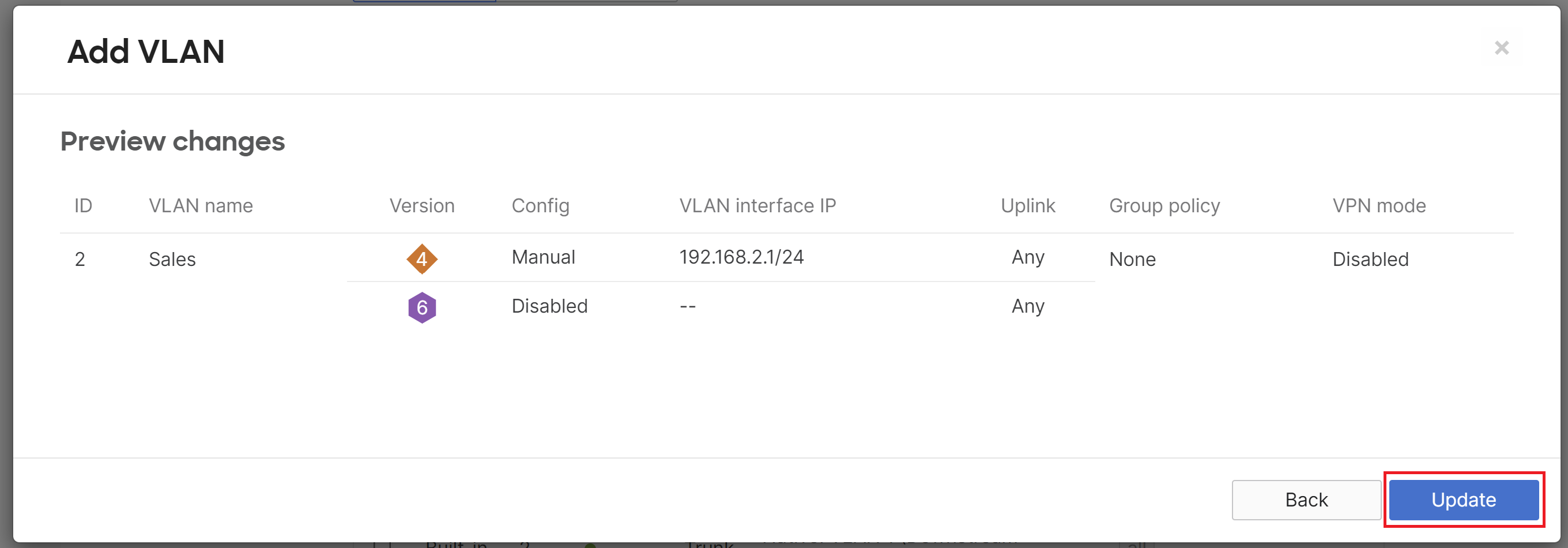
After VLANs have been enabled you can add additional VLANs by clicking Add VLAN.
Configuring more than 100 VLANs per network is not recommended.
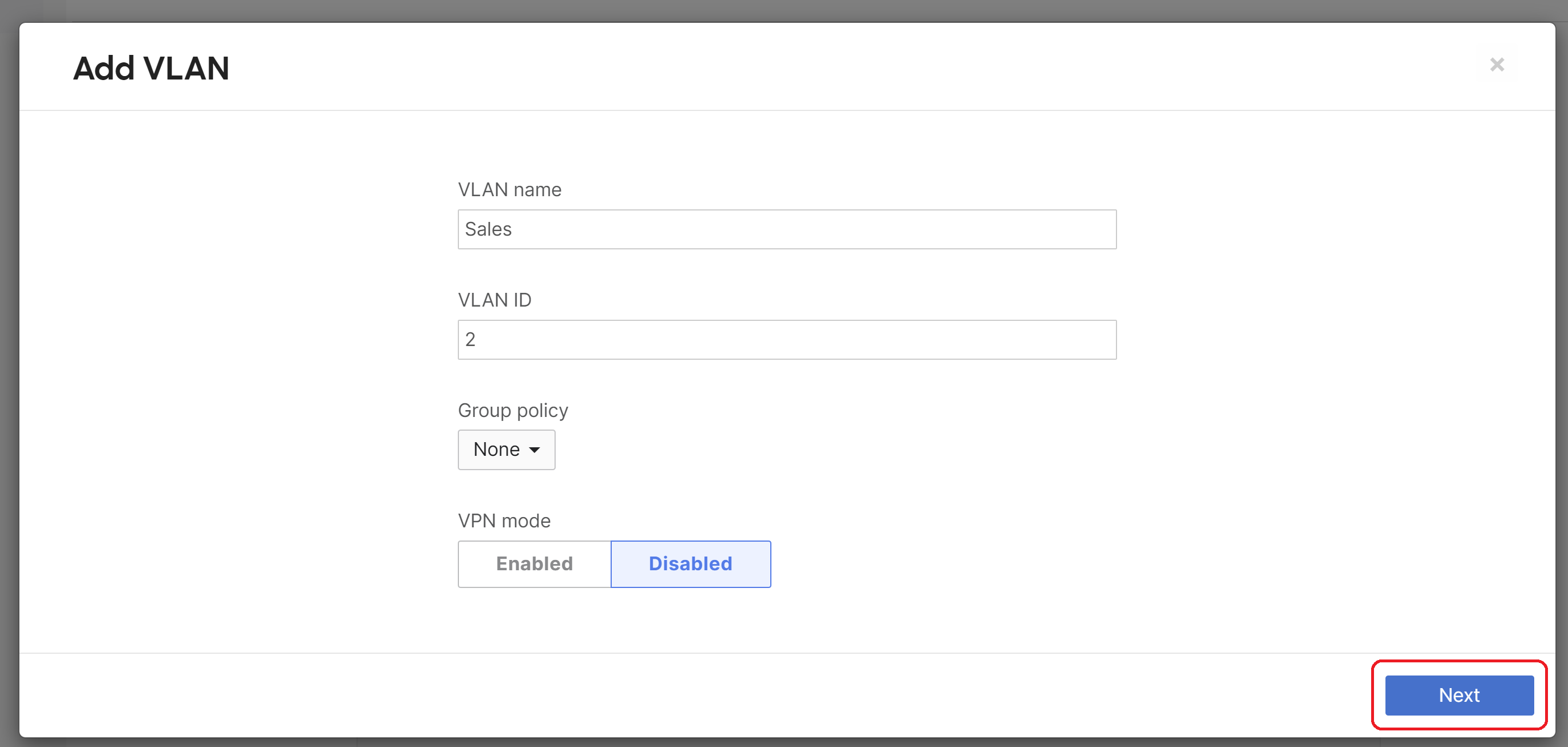
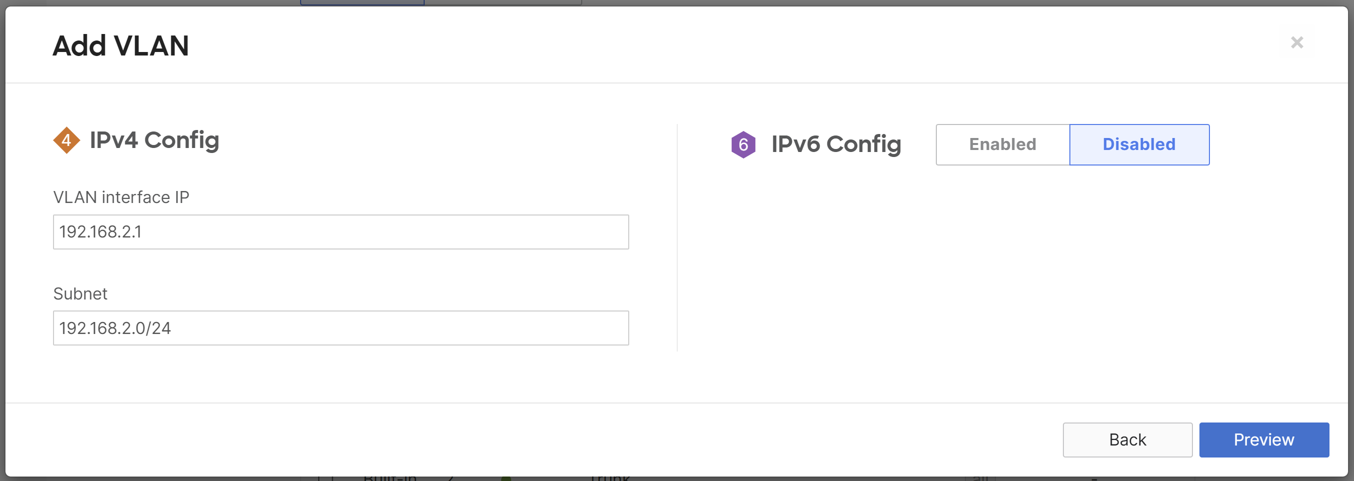
In this example, the WAN appliance has three VLANs:
- VLAN 1: 192.168.1.0/24
- VLAN 2: 192.168.2.0/24
- VLAN 3: 192.168.3.0/24
The VLAN Name is a description of the VLAN, the VLAN ID is the 802.1Q VLAN number, the Group Policy shows the name of the group policy applied to the VLAN (if any), the VLAN interface IP is the local WAN appliance's VLAN interface IP, and the Subnet is the network expressed using CIDR notation. A VLAN can be removed by checking the box next to the VLAN and clicking the Delete button. Click here for more detailed information about settings on Addressing & VLANs.
Warning: When scheduling a policy applied to a VLAN, traffic on the LAN will briefly drop as the configuration is applied. This will occur at the start and end of the schedule. Please take this into consideration when scheduling your group policy.
e.g., If production starts at 08:00, schedule the group policy to start earlier to ensure client connectivity is uninterrupted.
Configure LAN Ports
Next, the uplink ports to our switches will be configured as a trunk port to carry the VLANs that were configured in the previous step. Changes can be made to the MX LAN ports under Per-port VLAN Settings by selecting the check box beside the port number or by selecting multiple ports and clicking the Edit button.
The Type determines if the LAN port is an access or trunk port. When connecting the WAN appliance to a switch that will carry multiple VLANs, select trunk from the drop-down. Traffic without an 802.1Q tag will be dropped by default unless a native VLAN is defined from the Native VLAN field. You can specify specific VLANs that the trunk port will allow from Allowed VLANs or choose to allow all VLANs to pass on the link. Click here for more information about per-port VLAN configuration options.
\
Note: Modifying the enabled/disabled status of any LAN interface will reset the WAN interfaces, resulting in a connectivity loss on both Internet uplinks for up to 2 minutes. To minimize disruption, follow best practice and only make changes during a planned maintenance window.
Other Considerations
In some cases it is necessary to restrict access between different VLANs. Please refer to the following knowledge base document which describes how to use outbound firewall rules to restrict traffic between VLANs.
Please also note that deleting all VLANs will result in an error. If no VLANs are required, change the LAN setting to Single LAN mode.

