
Cisco Secure Access Meraki BGP Configuration Guide
Cisco Secure Private Access and Internet Access Configuration Guide
Cisco Secure Access offers a security stack solution from the cloud for internet, SaaS, ZTNA, Remote access connections, and more. Cisco Secure Access acts as a security gateway where 0.0.0.0/0 traffic will be routed for inspection and enforcement prior to internet or site-to-site, private cloud termination.

This document covers Secure Private access and/or Internet Access with BGP peering to Secure Access.
Meraki SDWAN + Secure Access Design Guide
Secure Internet Access Configuration Guide
Prerequisites
-
Cisco Secure Access account
-
Meraki MX/Z device (running MX19.1.6+ firmware)
-
Meraki MX/Z Site-to-site VPN enabled
Caveats and Considerations
-
ECMP/Load balancing is not supported with this integration
-
Cisco Secure Access Configuration
Go to sse.cisco.com and login with your credentials and follow the steps outlined below.
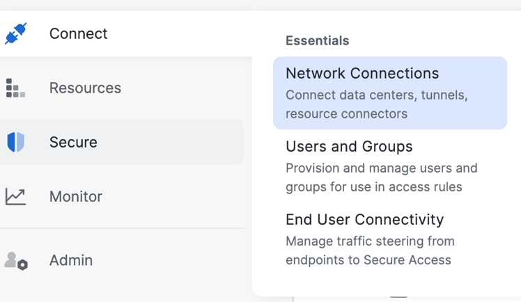
1. Add a Network Tunnel Group: From the Secure Access console, navigate to Connect > Network Connections.
-
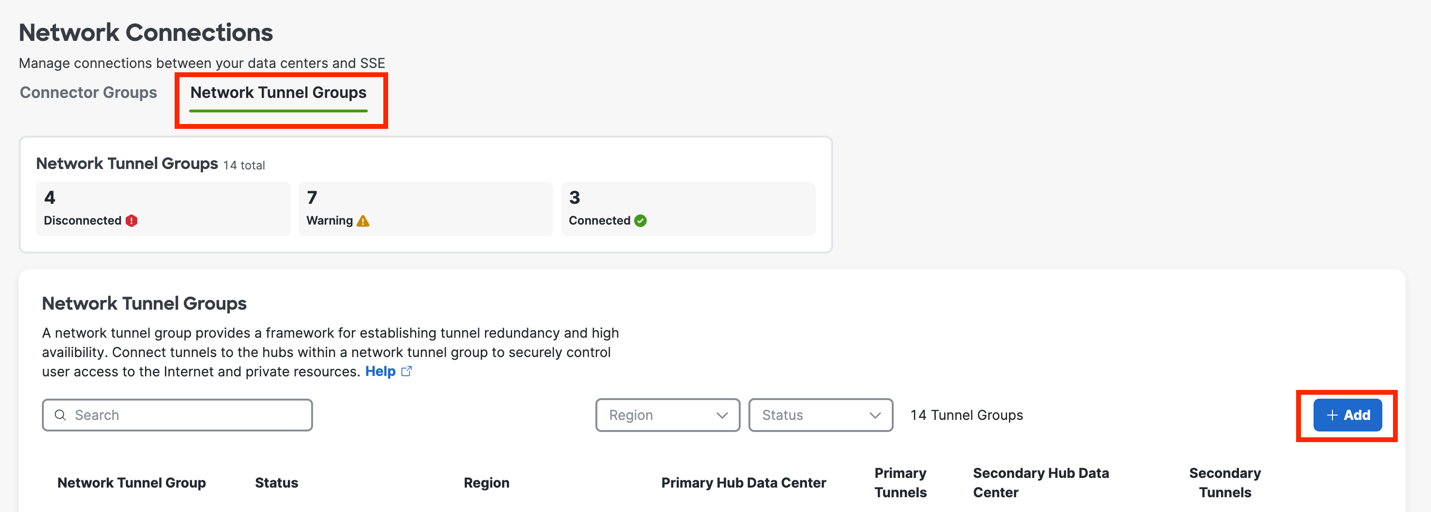
Select Network Tunnel Groups
-
Click Add
-
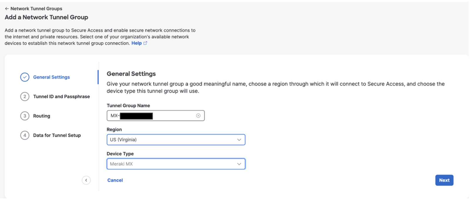
Enter the General Settings for your tunnel group:
-
Give your tunnel group a meaningful name
-
Choose a Region
-
Choose a Device Type
-
Click Next
-
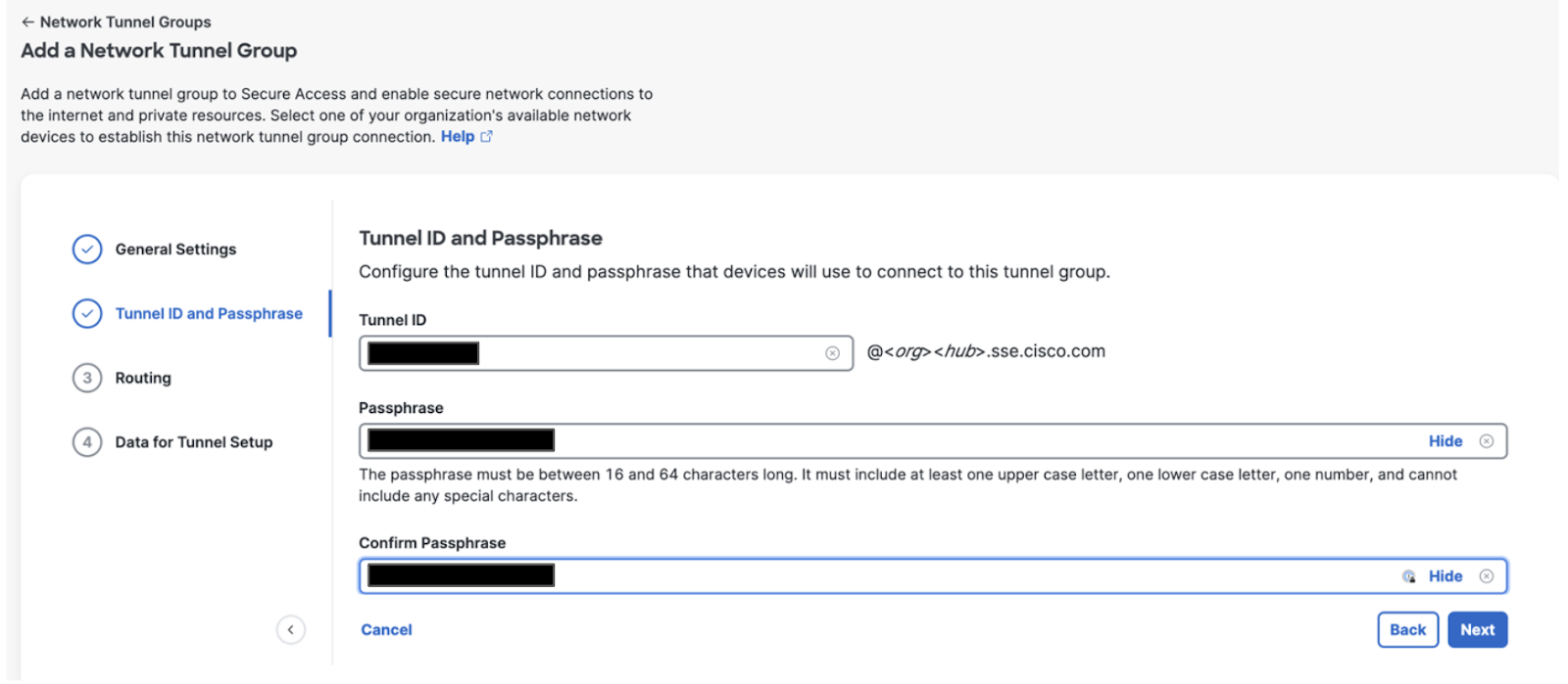
Enter the Tunnel ID and Passphrase for your tunnel group:
-
Tunnel ID Format: Email
-
Enter Passphrase
-
Re Enter Passphrase
-
Click Next
Note: The passphrase must be between 16 and 64 characters in length and contain at least one upper case letter, one lower case letter, and one number. The passphrase cannot include any special characters.
-
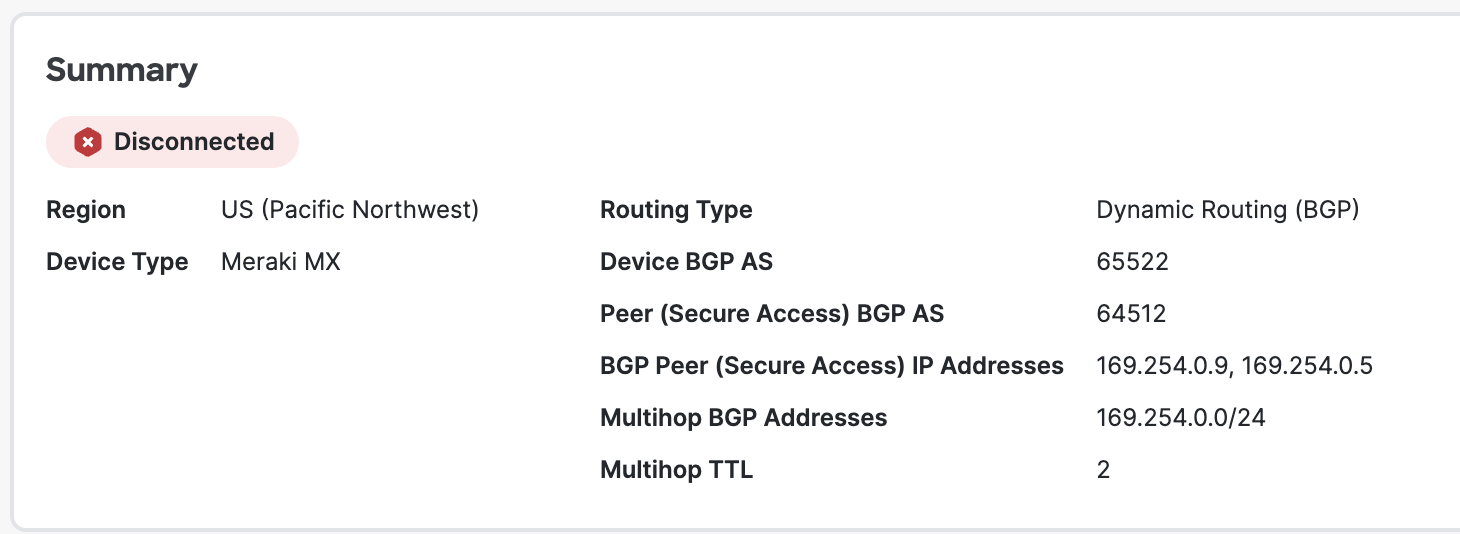
Choose Dynamic routing (for Private access and/or Internet Access use case)
-
Configure Meraki BGP AS number (this can be found on Meraki Dashboard > Security & SD-WAN > Routing page)
-
Enable Multihop BGP (required for BGP peering with Meraki SD-WAN)
-
Configure 169.254.0.0/24, as IP range for peering, Click Add
-
Set Hop count to 2
-
-
Enable Block default route advertisement (if necessary)

-
Click Save
-
On the Data for Tunnel Setup page, review the network tunnel information for completeness. Click the Download CSV button to save configuration information needed for your Meraki Secure SD-WAN device.
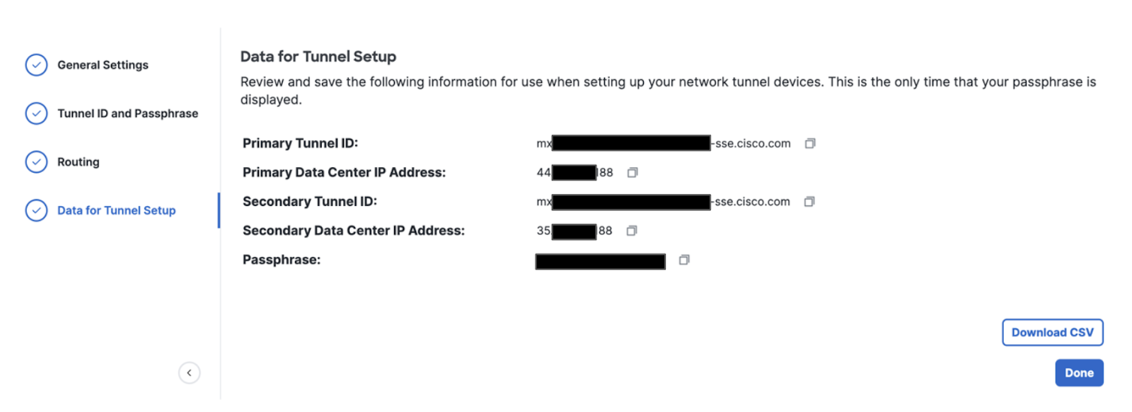
Note: This is the only time that your passphrase is displayed.
-
Click Done
A Network Tunnel Group will be configured but the Primary and Secondary Hub will be down until a tunnel is established to the Hubs.

Meraki Secure SD-WAN Configuration
In an AutoVPN and IPsec VPN environment, when configuration changes are applied on a Hub to a subnet that participates in the VPN, VPN connections will reset on every site connected to the Hub to update the VPN configuration.
Gather Details from Cisco Secure Access Portal
Information can be taken from the CSV downloaded from step 5 above or from the Data for Tunnel Setup page seen below:
On the Meraki Network, Navigate to Site-to-site VPN settings through the Security & SD-WAN > Configure > Site-to-site VPN page.
There are three options for configuring the MX-Z's role in the Auto VPN topology:

-
Off: The MX-Z device will not participate in site-to-site VPN.
-
Hub (Mesh): The MX-Z device will establish VPN tunnels to all remote Meraki VPN peers that are also configured in this mode, as well as any MX-Z appliances in hub-and-spoke mode that have the MX-Z device configured as a hub.
-
Spoke: This MX-Z device (spoke) will establish direct tunnels only to the specified remote MX-Z devices (hubs). Other spokes will be reachable via their respective hubs unless blocked by site-to-site firewall rules.
Select Hub (Mesh) or Spoke depending on your AutoVPN requirements, to enable VPN.
Configure Primary Secure Access Peer
Create a new IPsec peer by clicking on the "Add peer" button on the IPsec VPN peers table.
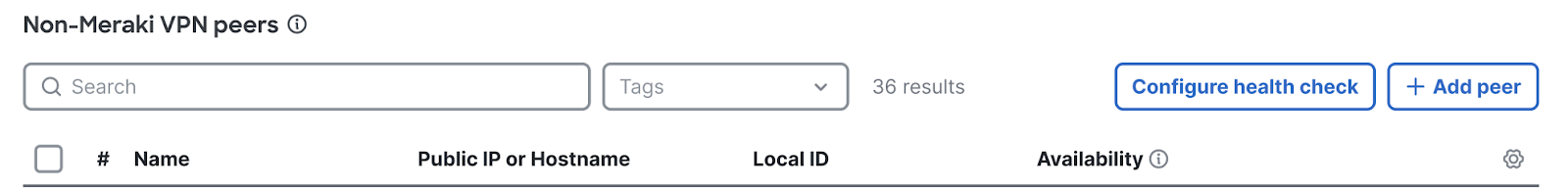
You can create Site-to-site VPN tunnels between a Security Appliance or a Teleworker Gateway and Cisco Secure Access under the IPsec VPN peers section on the Security & SD-WAN > Configure > Site-to-site VPN page.
When you add an IPsec VPN peer, under Routing you have - Static and Dynamic. With Dynamic selected, you see the following configuration options:
|
|
|


Click Add & Save
Creating a Secondary or Backup BGP Tunnel
A Secondary tunnel for BGP is just another tunnel with a lower priority. Simply create a new IPsec peer by clicking on the "Add peer" button on the IPsec VPN peers table:
|
|
|


- Save configuration
Verification and Troubleshooting
In an AutoVPN and IPsec VPN environment, when configuration changes are applied on a Hub to a subnet that participates in the VPN, VPN connections will reset on every site connected to the Hub to update the VPN configuration.
The Network Tunnel Group will move from Disconnected Status to Connected. This change could take a few minutes.
BGP peer will show up grayed out on the Security & SD-WAN > Routing page, and can only be removed when the peer is deleted via the Site-to-Site VPN page.

Next, we navigate to the Dynamic protocol status page to see if the eBGP peering relationship with our remote peer is up. An Established peer status indicates that the BGP neighbor relationship is established, and the “Routes” column indicates how many routes have been learned from the BGP neighbor.

-
Run ping tests from a tunnel enabled VLAN to the internet. For more information, see Using the Ping Live Tool.
-
Check the status of the VPN tunnel. For more information, see VPN Status Page.
-
Follow the VPN troubleshooting procedures. For more information, see Site-to-Site VPN Settings and Site-to-Site VPN Troubleshooting.
IPsec VPN Firewall
You can add firewall rules to control what traffic is allowed to pass through the VPN tunnel. These rules will apply to outbound VPN traffic to/from all MX-Z appliances in the Organization that participate in site-to-site VPN. These rules are configured in the same manner as the Layer 3 firewall rules described on the Firewall Settings page of this documentation. Note that VPN Firewall rules will not apply to inbound traffic or to traffic that is not passing through the VPN.
Serviceability
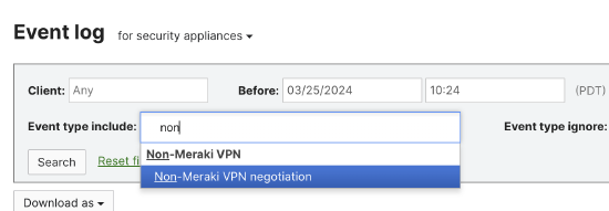
Event Logs
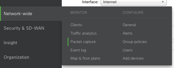
If you have any issues or would like to know more about the Cisco Secure Access peering details, navigate to Network-wide > Monitor > Event log.
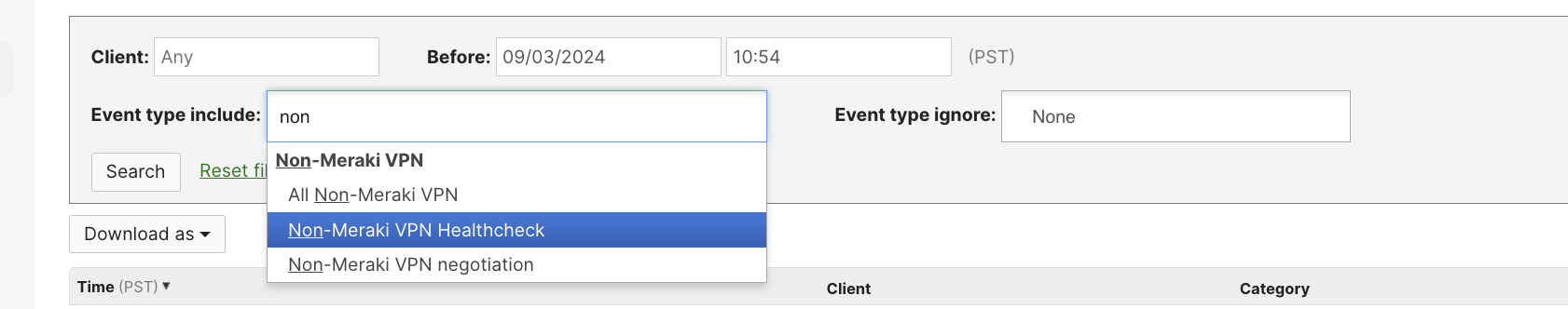
- Select Event type Include - Non-Meraki VPN Negotiation:
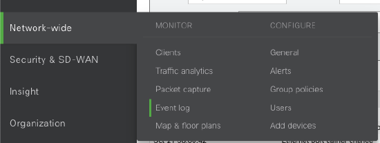
- IPsec VPN Healthcheck event type can be used to identify the recently reported healthcheck status of the tunnels:
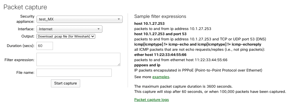
Packet Captures
The following options are available for a packet capture on MX/Z platforms:
-
Appliance: The appliance the capture will run on.
-
Interface: Select the interface to run the capture on; the interface names will vary depending on the appliance configuration. A few examples of interfaces you may see are:
-
Internet 1 or Internet 2 - Capture traffic on one active WAN uplink. Internet 2 will only appear if there is a second WAN link.
-
LAN - Captures traffic from all LAN ports.
-
Cellular - Captures cellular traffic from the integrated cellular interface. This does not apply to USB modems.
-
Site-to-Site VPN - Captures AutoVPN traffic (MX/Z to MX/Z only). This does not apply to IPsec VPN peers.
-
-
Output: Select how the capture should be displayed; view output or download .pcap.
-
Verbosity: Select the level of the packet capture (only available when viewing the output directly to Dashboard).
-
Ignore: Optionally ignore capturing broadcast/multicast traffic.
-
Filter expressions: Apply a capture filter.
To capture packets, select the WAN interface and use the filter expressions for UDP 500 for Phase 1 or UDP 4500 for Phase 2.
API
The Meraki dashboard API is an interface for software to interact directly with the Meraki cloud platform and Meraki-managed devices. The API contains a set of tools known as endpoints for building software and applications that communicate with the Meraki dashboard for use cases such as provisioning, bulk configuration changes, monitoring, and role-based access controls. The dashboard API is a modern, RESTful API using HTTPS requests to a URL and JSON as a human-readable format. The dashboard API is an open-ended tool that can be used for many purposes.
For more information, read here.
24/7 Support
Cisco Meraki Support is available 24/7 to Enterprise customers for assistance with resolving network issues and providing answers to questions not covered by the documentation. For more information, read here.