IKEv1 and IKEv2 for IPsec VPN Peers Compared
MX15.x firmware introduces the ability to chose between IKEv1 and IKEv2 for IPsec VPN peers. However, the two protocols function significantlly differently in terms of how IPsec tunnels are built, and this guide is intended to illustrate these differences, and when one can be used over the other.
IKEv1
Using IKEv1 allows for any number of IPsec security associations* (SAs) to be built between between an MX or Z3 device and a given 3rd-party device, or a Meraki device in a separate Dashboad Organization.
However, since IKEv1 as a protocol restricts a security association to a single source and destination, this introduces overhead and scale concerns. Each pair of subnets in a VPN requires at least two SAs for bidirectional communication, which means the required number grows in a non-linear fashion as more subnets are added. This may also cause issues with certain cloud service providers, who have limits on how many concurrent SAs can be established at a time (e.g. AWS)
*A security association (SA) describes a means of securely sending traffic from a given source or set of sources to a given destination or set of destinations when IPsec is in use.
A single SA can effectively be considered half of a working IPsec tunnel, since it can send traffic from A to B, but not from B to A.
The formula to calculate the maximum number of SAs that will be keyed between an MX and a 3rd-party device when IKEv1 is in use is T=2*m*n where m is the number of subnets on the Meraki device, and n is the number of subnets on the 3rd-party device.
IKEv1 example
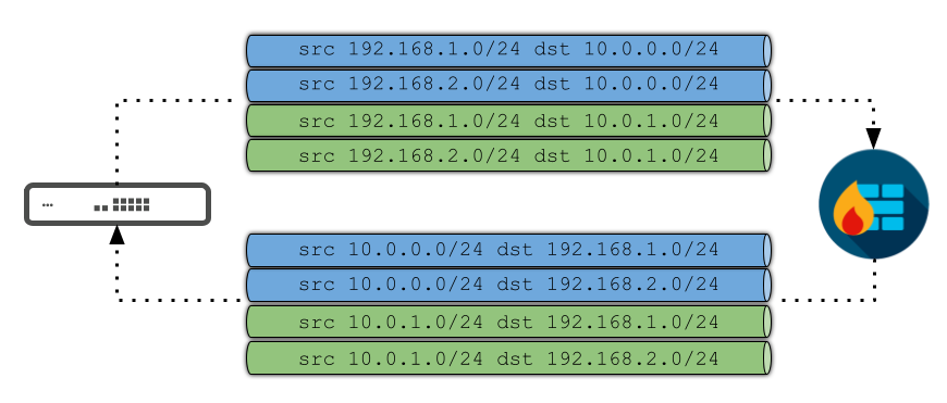
The following example visualizes how the security associations would logically appear between an MX appliance and a 3rd-party peer that each have two subnets participating in a VPN with IKEv1:

Following our formula above, in this example, m=2, and n=2. As a result, the equation is T=2*2*2 or T=8 for the total of SAs that must be keyed for full connectivity in each direction.
Note however, that since SAs are keyed on demand (i.e. only when traffic from a given source needs to reach a IPsec VPN peer for which an SA doesn't already exist), the maximum number needed may not always be active at a given point in time.
IKEv2
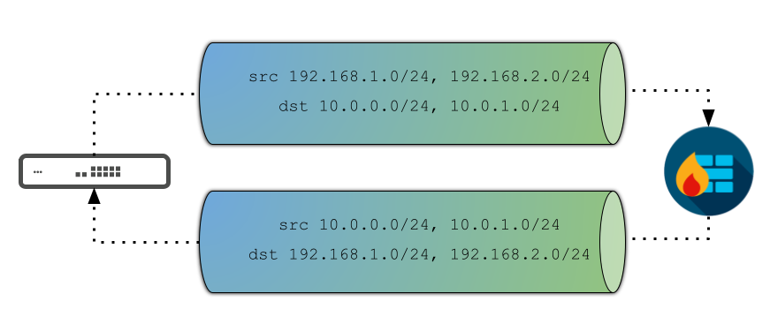
Unlike IKEv1, Meraki's IKEv2 implementation - by design - only allows for a single pair of IPsec security associations between an MX or Z3 device and a given 3rd-party firewall, or a Meraki device in a separate Dashboard Organization.
However, IKEv2 does not place restrictions on the number of sources and destinations in an IPsec SA. This means a single pair of SAs can provide full connectivity between two peers, regardless of how many subnets are involved, as the following illustration shows:

As a result, IKEv2 can allow us to scale up significantly higher than IKEv1, since there's no need to keep keying additional SAs as more subnets are added.
Unfortunately, there are known compatibility issues this presents to certain vendors - strongSwan is the process Meraki devices utilize to build tunnels to IPsec VPN devices and for L2TP/IPsec Client VPN - as some that continue to enforce the IKEv1 restriction of a single set of src/dst subnets per SA in their IKEv2 implementations (e.g. Cisco ASAs)
Such implementations generally respond to requests to key an IPsec SA by only using a single pair of subnets. When this happens, it blocks any further subnets from participating in the VPN until the SA expires.
IKEv2 working vs. non-working example packet captures
The following two excerpts* from packet captures illustrate what a working exchange looks like, and what an incompatible exchange looks like.
*The data seen in these captures is normally encrypted in transit, and cannot be seen without enabling additional debugging on one of the peering devices, and plugging the obtained decryption information into an application like Wireshark.
Such debugging is only possible on Meraki devices by contacting Support, and requires tearing down and re-establishing the tunnels in question.
Working
The following excerpt shows part of a successful IKEv2 exchange between two devices, forming a VPN between the subnets 192.168.1.0/24 and 192.168.2.0/24 on one end, and 192.168.3.0/24 and 192.168.4.0/24 on the other:

Given that there are four different Traffic Selector payloads in this single packet, the MX is attempting to establish a single security association that covers all 4 of the involved subnets, and the peer acknowledges this by sending a response that includes all 4 as well.
The net result of this exchange is a working pair of SAs that allows bi-directional connectivity between all of the involved subnets.
Non-working
The following excerpt shows part of an IKEv2 exchange between two devices, attempting to form a VPN between the subnets 192.168.1.0/24 and 192.168.2.0/24 on one end, and 10.5.10.0/24 and 10.5.20.0/24 on the other:

As with the previous capture, the MX is attempting to build a single SA that covers all 4 of the involved subnets, but in this case, the peer responds with only a single Traffic Selector pair, indicating it only wants the tunnel to cover 192.168.2.0/24 and 10.5.20.0/24.
Because this is permissible by the IKEv2 standard, the net result of this is a pair of SAs that allows only those two subnets. Any further attempts to bring up tunnels that cover additional subnets will be rejected by the MX until they expire.
A formal definition on how this process operates can be found under RFC 7296 Section 2.9

