

Troubleshooting PoE on MS switches
Click 日本語 for Japanese
Overview
This article provides a basic understanding of how Power over Ethernet (PoE) is provisioned on Cisco Meraki MS switches and includes troubleshooting procedures to help identify PoE failures on a switch or switch port.
This article covers the following topics:
-
PoE provisioning
-
PoE underload alerts
-
PoE overload alerts
-
Physical layer troubleshooting
-
PoE negative current errors
Troubleshooting PoE provisioning
PoE provisioning occurs during the initial link negotiation between the end device, or Powered Device (PD), and the switch, or Power Sourcing Equipment (PSE). During this communication, the PD informs the switch of its power requirements, and the switch uses this information to determine the amount of power to allocate to the connected device.
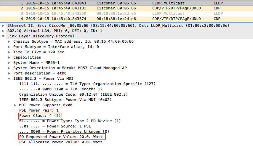
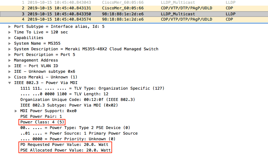
During link negotiation, the PD sends an Link Layer Discovery Protocol (LLDP) packet containing its requested power value. The PSE receives this request and allocates power accordingly. The LLDP packet sent by the switch displays the allocated power.
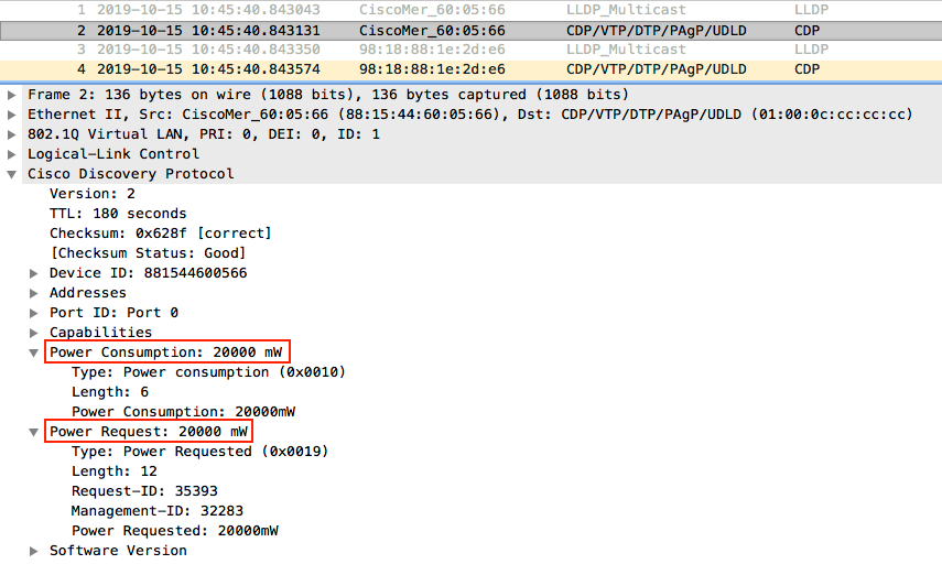
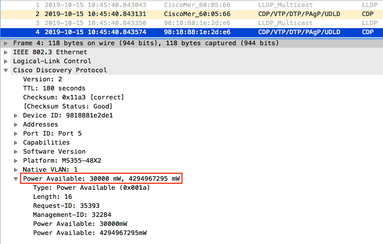
The Cisco Discovery Protocol (CDP) packet sent by the PD reports the Power Consumption and Power Request values. The CDP packet sent by the switch reports the Power Available value, which is typically higher than the Power Requested value because the switch allocates an upper power limit for the PD based on the power class reported during link negotiation.
Troubleshooting steps
-
Start a dashboard packet capture on the switch port where the PoE device is connected.
-
If the PD supports CDP or LLDP, continue with the following steps.
-
If the PD does not support CDP or LLDP, refer to the PoE Support on MS Switches article for information about how the switch provisions PoE for these devices.
-
For more information, refer to Packet Capture Overview.
-
-
Verify that the LLDP packet sent by the switch shows the power allocated based on the power requested by the PD.
-
Verify the following field:
-
Link Discovery Protocol > IEEE 802.3 > Power Via MDI > MDI Power Support > PD Requested Power Value
-
This field displays the power requested by the PD during link negotiation.
-
-
-
Review the CDP packet sent by the PD.
-
Verify the following fields:
-
Cisco Discovery Protocol > Power Consumption
-
Verify that the field displays the Power Consumption value reported by the PD.
-
-
-
Review the LLDP packet sent by the switch.
-
Verify the following field:
-
Link Discovery Protocol > IEEE 802.3 > Power Via MDI > MDI Power Support > PSE Allocated Power Value
-
Verify that the field displays the Power Allocated value and the Class of Operation reported by the switch.
-
-
-
Review the CDP packet sent by Power Sourcing Equipment (PSE).
-
Verify the following field:
-
Cisco Discovery Protocol > Power Available
-
The Power Available value is typically higher than the Power Requested value because the switch allocates an upper power limit based on the power class reported during negotiation.
-
-
Example
The following example uses a packet capture collected on port 5 of an MS series switch (PSE) during link negotiation with a Meraki MR series access point (PD). Although this example uses Cisco Meraki devices, the same packet analysis applies to other devices that receive PoE from the switch.
Note: The previous dashboard packet capture tool allowed packet captures on interfaces that were down or disconnected. The Intelligent Packet Capture tool requires the switch port to be active. If the switch port is down, the packet capture fails with a 422: Capture Failed error. Verify that the switch port is up before starting the packet capture.
The LLDP packet shows that the access point requests 20 W during link negotiation and operates as Class 4.
The following screenshot shows the Power Class and Power Requested values reported by the PD during link negotiation.
The following screenshot shows CDP packet sent by the access point reports the Power Consumption and Power Request values.
The LLDP packet sent by the switch shows that the switch allocates the requested power to the access point.
The following screenshot shows the Power Allocated value and the Class of Operation reported by the switch.
The CDP packet sent by the switch shows that the switch budgets 30 W of power based on the negotiated PoE power class, even though the access point requests 20 W. The 30 W value represents the upper power limit available to the connected device and does not indicate the device's actual power consumption.
The following screenshot shows the Power Available value reported by the switch.
Note: The switch budgets power based on the PoE classification reported by the connected device. The PoE budget can exceed the maximum available switch power because it represents the potential power allocation rather than the actual power consumption. Devices continue to receive power until the actual power consumption exceeds the maximum power available on the switch. If the available power is exceeded, lower-numbered ports take precedence, and the switch removes power from higher-numbered ports.
Troubleshooting PoE underload and overload alerts
PoE underload alerts
A PoE underload event occurs when a PoE-powered device uses less power than the specification allows for an extended period. This can occur if the device is not operating correctly or if it powers down too slowly.
PoE overload alerts
A PoE overload event occurs when a PoE-powered device draws more power than it is designed to handle or exceeds the negotiated power allocation with the switch, regardless of the total power budget available.
Troubleshooting the physical layer
Rule out physical layer issues when troubleshooting PoE on Cisco Meraki MS switches.
Troubleshooting steps
-
Verify that the switch supports PoE.
-
Cisco Meraki PoE-capable switches have a P at the end of the model number, for example, MS220-24P.
-
For more information, refer to the MS Family Datasheet.
-
-
Verify that PoE is enabled on the switch port connected to the PD.
-
Navigate to: Switches > Configure > Switch ports
-
Select the affected port and set PoE to Enabled.
-
Review the current PoE status for the switch port.
-
Select Details to view the current PoE status.
-
For more information, refer to Configuring PoE on MS Switches.
-
-
If the switch is powered by a Uninterruptible Power Supply (UPS), connect the switch directly to a wall outlet and verify whether the issue persists.
-
Connect the PD to:
-
Another switch port.
-
A PoE injector.
-
A PoE-capable switch.
-
-
-
Connect a non-PoE device, such as a laptop, to the affected switch port.
-
Determine whether another connected device is supplying PoE to the switch.
-
If a connected device supplies PoE to the switch instead of drawing power from it, the switch may disable PoE to prevent damage.
-
Disconnect connected devices one at a time and verify whether PoE resumes after disconnecting a specific device
-
-
Perform a factory reset on the switch.
Additional resources
Configuring PoE on MS Switches
Requesting an Return Merchandise Authorization (RMA)
If the troubleshooting procedures in this article indicate that the switch requires replacement, contact Cisco Meraki Support to begin the (RMA) process.
Be prepared to provide the following information:
- The troubleshooting steps completed.
- The shipping address for the replacement device.
For more information about device replacement, refer to the RMA documentation article.
Note: Cisco Meraki Support may recommend additional troubleshooting steps that are not included in this article, depending on the nature of the issue.
Related documents