
Campus Gateway Design and Best Practice Guide
Introduction and purpose
The Campus Gateway is the cloud-native solution from Cisco for centralized wireless deployments, serving a similar role to a wireless LAN controller (WLC) by terminating tunneled data plane traffic from APs and switching it to the rest of the network.
Here is a list of the key benefits of the Campus Gateway design:
-
Centralized traffic termination - Client VLANs only need to exist in the core, removing the need to span VLANs across all access switches.
-
Seamless roaming across L3 domains - By terminating traffic centrally at the Campus Gateway, clients can roam across Layer 3 boundaries of the APs without losing their IP address or breaking their session.
-
Overlay design with minimal wired-side changes - Traffic is tunneled from APs to the Campus Gateway using an overlay, so the existing underlay switching network does not need to be redesigned. As long as APs and Campus Gateway have IP connectivity, control plane and data plane tunnels will form.
-
Reduced broadcast domain size - Client VLANs are limited to the connection between the Campus Gateway and the upstream core/distribution switch, which contains the broadcast domain to a much smaller area.
-
Simplified migration from controller-based deployments - Moving from a traditional customer-managed Catalyst wireless deployment can be as simple as migrating to cloud-managed APs and replacing the WLC with the Campus Gateway.
Architecture components
The Campus Gateway is a purpose-built appliance for data plane aggregation and real-time control plane services for wireless traffic. While it serves a similar traffic aggregation purpose as a WLC and shares the same hardware as the WLC, it is not a cloud-managed WLC.
Hardware
-
Cisco Campus Gateway appliance (shares the same hardware platform as the CW9800H1 and CW9800L WLC)
-
Cloud-managed Cisco APs (MR and CW series)
-
Core/distribution switches (upstream from the Campus Gateway)
-
Access switches (for AP connectivity)
Software/Firmware
- Campus Gateway firmware:
- CW9800H1-MCG: MCG 31.2.X or later
- CW9800L-MCG: MCG 32.2.X or later
- Access Point firmware:
- Tunneling to CW9800H1-MCG: MR 31.2.X or later
- Tunneling to CW9800L-MCG: MR 32.2.X or later
Note: Campus Gateway and AP firmware versions must be identical (for example, if the Campus Gateway runs MCG31.2.5, APs must run MR31.2.5)
Licensing requirements
The Campus Gateway does not require a separate license, and technical support is included under active licensing for associated access points.
For more information, refer to the “Licensing Requirements” section in the Campus Gateway Deployment Guide.
Best practices
Recommended design principles
-
Limit client VLANs to the core/distribution layer. Terminate client VLANs only on the connection between the Campus Gateway and the upstream switch to reduce broadcast domain size.
-
Ensure IP connectivity between APs and the Campus Gateway. This is the only requirement for the control plane and data plane tunnels to establish properly.
-
Deploy Campus Gateway for medium to large campus environments. For small to medium sized deployments, such as branch offices or single buildings with 300 APs or less, a traditional distributed deployment with local switching may be sufficient. For deployments with more than 300 APs, it is recommended to deploy a Campus Gateway for a centralized deployment.
-
Do not use MX as a wireless concentrator for large campus deployments. While MX is still available as an option in dashboard, it has various scale limitations and has not been tested for large wireless deployments.
Why is a centralized deployment needed?
Traditionally, Cisco cloud-managed wireless deployments use a distributed model where each AP locally switches client traffic via a Layer 2 (L2) trunk port to the access switch. Because of this, client VLANs must span across all access switches where seamless roaming is required. If the VLANs do not span, the client would need to obtain a new IP address when roaming, resulting in a broken session. This distributed method is completely sufficient for small to medium sized deployments, such as branch offices or individual buildings, where the same VLAN can be shared and spanned across all switches to create an L2 roaming domain.
However, as cloud-managed wireless deployments grow to medium and large campus sizes (for example, university campuses), the limits of a distributed wireless design are reached:
-
Spanning L2 VLANs across all access switches creates a large broadcast domain.
-
The number of wireless clients begins to overwhelm the ARP and MAC address tables of the access switches. Every wireless client needs to be in the tables for every access switch where the L2 VLAN is defined.
-
When a client roams between APs, each switch must update its tables, which is a CPU-intensive task.
-
Spanning tree implications and BUM (Broadcast, Multicast, and Unknown Unicast) traffic become increasingly difficult to manage in a large L2 network.
-
When thousands of clients are roaming, the CPU utilization on every switch becomes extreme, potentially leading to switch failures.
By centralizing wireless traffic at the Campus Gateway, client VLANs only need to exist on the connection between the Campus Gateway and the upstream switch. This upstream switch is typically the core or distribution switch, which has much greater scale and capacity compared to access switches. Limiting client VLANs to the upstream switch also contains the broadcast domain to a much smaller area.
Additionally, the Campus Gateway deployment uses an overlay design. Rather than redesigning the underlay switching network to account for wireless traffic being switched via L2 trunks at the AP level, traffic is tunneled from the AP to the Campus Gateway. As long as the APs and Campus Gateway have IP connectivity, the control plane and data plane tunnels will form, meaning very few changes to the wired infrastructure are needed.
Moving from a traditional customer-managed Catalyst wireless deployment should be as simple as migrating to cloud-managed APs and replacing the WLC with the Campus Gateway.
How is Campus Gateway different from MX?
Although MX is still available as an option in dashboard to serve as a wireless concentrator to tunnel wireless client traffic to a centralized box, it is not recommended for large campus deployments. MX as a concentrator has various scale limitations and has not been tested for large wireless deployments.
The Campus Gateway architecture is fundamentally different, with different scalability and tunneling technologies. These are all implemented in hardware, making the Campus Gateway ideal for scaling to large campus requirements.
Additionally, the Campus Gateway provides unique features that are not available in MX:
- Centralized client database for seamless roaming
- RADIUS proxy
- mDNS gateway
Security considerations and compliance
- QUIC tunnels are encrypted using TLS with dashboard-provisioned keys or certificates, securing all control plane communication between the APs and the Campus Gateway.
- RADIUS proxy functionality is built into the Campus Gateway, with RADIUS messages carried inside the VXLAN data plane tunnel.
- Policy and security tags are carried in the VXLAN tunnel header, including DSCP and SGT (Security Group Tag) information, supporting end-to-end policy enforcement.
Performance, scalability, and reliability guidelines
Performance guidelines
Here is a list of the key performance guidelines to follow:
- Ensure the MTU between APs and the Campus Gateway accommodates VXLAN overhead. The VXLAN encapsulation adds 50 bytes of overhead (Outer IP: 20 bytes, UDP: 8 bytes, VXLAN: 8 bytes, MAC: 14 bytes). For an MTU of 1500 bytes, the largest IP packet that can be transmitted without fragmentation is 1450 bytes.
- TCP MSS adjustment is performed by the AP to avoid fragmentation. The largest frame is adjusted to 1410 bytes for IPv4 traffic (40 bytes less) and 1390 bytes for IPv6 traffic (60 bytes less).
- The Do Not Fragment (DF) bit is always set in the Outer IP header of the VXLAN tunnel. If the inner IPv4 packet has the DF bit set and the total packet size exceeds the Path MTU, the AP or Campus Gateway will send an ICMP Too Big message back to the sender.
- Jumbo frames on APs are not currently supported.
Scalability guidelines
Here is a list of the key scalability guidelines to follow:
- A standalone or clustered Campus Gateway supports up to 5,000 Access Points and 50,000 clients.
- A standalone Campus Gateway provides up to 100 Gbps of throughput.
- A cluster of two Campus Gateways provides up to 200 Gbps of throughput.
- For large campus deployments with thousands of roaming clients, centralized deployment via Campus Gateway is recommended to avoid overwhelming the ARP and MAC address tables of access switches. In a distributed deployment, every wireless client needs to be in the tables for every access switch where the L2 VLAN is defined, and roaming events force CPU-intensive table updates across all switches.
Reliability guidelines
Here is a list of the key reliability guidelines to follow:
- Each AP establishes a QUIC tunnel to each Campus Gateway in the cluster, with regular keepalives sent to check the status of the Primary and Backup Campus Gateway.
- BFD (Bidirectional Forwarding Detection) monitoring is implemented on the VXLAN connection to identify and track AP connections, even when two flows between the AP and Campus Gateway take different network paths. For more information, see RFC 8971.
- High availability messages and inter-Campus Gateway traffic are carried over the QUIC control plane tunnel, supporting failover between the Primary and Backup Campus Gateway in a cluster.
Technical Architecture
Architecture of a Campus Gateway Deployment
While the Campus Gateway serves the same purpose in terms of client traffic aggregation as a WLC and shares the same hardware as the CW9800H1 WLC, it is not a cloud-managed WLC. It is a purpose-built appliance for data plane aggregation and real-time control plane services for wireless traffic.
To meet large-scale roaming requirements, certain aspects of the wireless network need to be brought back to a centralized on-premises appliance while keeping the rest on Dashboard and APs.

The following list includes a breakdown of these functions:
- Meraki dashboard
- Management plane
- Configuration management
- Monitoring and troubleshooting
- Software management
- Licensing
- Serviceability/debugging
- Non-real-time control plane
- RRM (AI-RRM)
- Air Marshal
- Rogues
- Management plane
- Campus Gateway
- Data plane
- Data plane termination
- VLAN termination
- Real-time control plane
- AAA Proxy
- Roaming – key management
- Dstore (client DB)
- mDNS Gateway
- Data plane
- MR AP
- Data plane
- Bridge local SSIDs
- Tunnel central SSIDs
- QoS
- Rate Limit
- Adaptive policy tagging
- Real-time control plane
- Client authentication
- Client state machine
- Telemetry
- Data plane
How do the devices communicate with each other and the dashboard?

Management plane
Like existing cloud-managed devices, both the Campus Gateway and APs are managed directly and natively by dashboard. This is the same management model used for MR, MS, MX, and other cloud-managed Cisco devices today. Each device maintains its own Meraki Tunnel connection to the cloud.
The Campus Gateway does not serve any management function. It is an overlay L3 tunnel solution for bridging client traffic into the network core.
Control plane
The control plane (CP) tunnel between the Campus Gateway and APs uses the QUIC protocol. The CP tunnel carries messages such as:
- AP registration
- Client anchoring
- High availability messages
- Inter-Camous Gateway traffic
About the QUIC Protocol:
QUIC is a UDP-based transport protocol developed to be as reliable as TCP without suffering from the overhead associated with TCP. TCP suffers from head-of-line blocking, where messages are sent as a single byte stream. If one large packet needs to be retried, all subsequent packets in the stream are blocked until that packet is successfully sent. With QUIC, traffic is sent in multiple streams. If one packet is lost, only the stream that the packet belongs to is affected, while the rest continue to operate normally.
QUIC Tunnel Security:
QUIC tunnels are secured via TLS encryption with dashboard-provisioned keys or certificates.
QUIC Tunnel Behavior:
Each AP establishes a QUIC tunnel to each Campus Gateway in the cluster, with regular keepalives sent to check the status of the Primary and Backup Campus Gateway.
Port Information:
The QUIC tunnel operates on UDP port 16674 on both the Campus Gateway and the AP.
Data plane
The data plane (DP) tunnel between the Campus Gateway and APs uses the Virtual eXtensible Local Area Network (VXLAN) protocol. These are stateless and transient tunnels that rely on per-packet encapsulation using the standard VXLAN encapsulation format.
Purpose:
The VXLAN tunnel carries client data packets, which are then bridged onto the client VLANs at the Campus Gateway.
Tunnel Header Information:
The tunnel header carries QoS and policy information, including:
- DSCP
- SGT (Security Group Tag)
RADIUS messages are also carried inside the VXLAN tunnel.
Connection Monitoring:
There is a possibility for two flows between the AP and Campus Gateway to take different network paths. To identify which connections belong to which AP and to monitor the health of these connections, a monitoring check is implemented on the VXLAN connection. This uses the Bidirectional Forwarding Detection (BFD) mechanism for VXLAN (for more information, see RFC 8971).
The VXLAN tunnel will operate on UDP port 16675 on both Campus Gateway and AP.
Path MTU discovery
The Path MTU calculation between the APs and Campus Gateway is done through the QUIC tunnel and is calculated for both the QUIC and VXLAN tunnels. For the VXLAN tunnel, the Do Not Fragment (DF) bit is always set in the Outer IP header.

Before adding the VXLAN encapsulation over the client traffic, both the AP and Campus Gateway will fragment the inner IP packet (client traffic) if the total packet size, including the VXLAN encapsulation, exceeds the Path MTU. If the inner IPv4 packet has the DF bit set and the total packet size is too large, the AP or Campus Gateway will send an ICMP Too Big message back to the sender.
How big of a packet can be sent?
Assuming the Path MTU calculated is 1500 bytes, the VXLAN tunnel overhead is 50 bytes:
|
Component |
Size |
|
Outer IP |
20 bytes |
|
UDP |
8 bytes |
|
VXLAN |
8 bytes |
|
MAC |
14 bytes |
|
Total Overhead |
50 bytes |
The largest IP packet that can be transmitted without fragmentation is 1450 bytes.

If TCP traffic is sent, the AP implements TCP MSS (Maximum Segment Size) adjustment to avoid fragmentation:
|
Traffic Type |
Maximum Frame Size |
Reduction |
|
IPv4 |
1410 bytes |
40 bytes less than 1450 |
|
IPv6 |
1390 bytes |
60 bytes less than 1450 |
Note: Jumbo frames on APs are not currently supported.
Recommended upstream switches and topology
The Campus Gateway supports up to 50,000 clients. To take advantage of full scale, the upstream switch must have MAC and ARP tables that exceed this capacity.
Full scale:
|
Switch Family |
Model |
MAC Table Scale |
ARP Table Scale |
Meraki Cloud Monitoring Support |
|
Cisco Catalyst 9600 |
C9600X-SUP-2 |
256K |
128K |
No |
|
Cisco Catalyst 9600 |
C9600-SUP-1 |
128K |
90K |
No |
|
Cisco Catalyst 9500 |
UADP 3.0 based |
82K |
90K |
Yes |
|
Cisco Catalyst 9500 |
UADP 2.0 based |
64K |
80K |
Yes |
|
Cisco Catalyst 9500X |
N/A |
256K |
256K |
Yes |
|
Cisco Nexus 7000/7700 |
M3 Line Cards |
384K |
N/A |
No |
|
Cisco Nexus 7000/7700 |
F3 Line Cards |
64K |
N/A |
No |
|
Cisco Nexus 9500 |
N/A |
90K |
90K (60K v4 / 30K v6) |
No |
|
Cisco Nexus 9300 |
9300 Platforms |
90K |
65K (40K v4 / 25K v6) |
No |
|
Cisco Nexus 9300 |
9300-FX/X/FX2 |
92K |
80K (48K v4 / 32K v6) |
No |
|
Cisco Nexus 9200 |
N/A |
96K |
64K (32K v4 / 32K v6) |
No |
Partial Scale:
If only partial scale is needed, a lower-capacity switch can be used. However, as scale increases, the MAC and ARP table limits of those switches will be reached.
Note: The Cisco Catalyst 9300 and 9300-M models support up to 35,000 MAC addresses, which is not sufficient for a full-scale Campus Gateway.
Recommended uplink topology
Two supported upstream switch topologies are available. For both, use a switch deployment where multiple switches act as a single logical switch (for example, VSS, SVL, vPC) or in HSRP. If multiple Campus Gateways are deployed (maximum of two in a cluster), the uplink switch will have a unique port-channel configured for each Campus Gateway.
Option 1: using split links
In Option 1, the connection for each Campus Gateway to the upstream switch stack uses split links to each switch in the stack. For each Campus Gateway, there will be an equal number of links to each switch in the stack, with all links placed in a single port-channel.

Advantages:
- Link redundancy for each Campus Gateway to the upstream switch
- If one switch in the stack fails, the Campus Gateways still have a connection to the rest of the network through the remaining switches
Drawbacks:
- Total throughput per Campus Gateway decreases when a switch fails because there are fewer active links
Best for: Deployments where keeping the number of Campus Gateway chassis up in a cluster is more important than throughput.
Option 2: without split links
In Option 2, the connection for each Campus Gateway does not use split links. The switches can be a logical stack (StackWise Virtual, VSS, etc.) or a pair of standalone switches configured in HSRP. Each Campus Gateway connects all its links to a specific switch and forms a single port-channel.

Advantages:
- Link redundancy for each Campus Gateway to its upstream switch
- If one switch fails, the remaining Campus Gateways maintain full throughput
Drawbacks:
- If a switch fails, the Campus Gateway connected to that switch also goes down since it has no path to the rest of the network
- APs must fail over to the other Campus Gateway in the cluster, causing wireless traffic disruption
Best for: Deployments where the highest throughput is the priority.
Recommended cluster deployment topologies
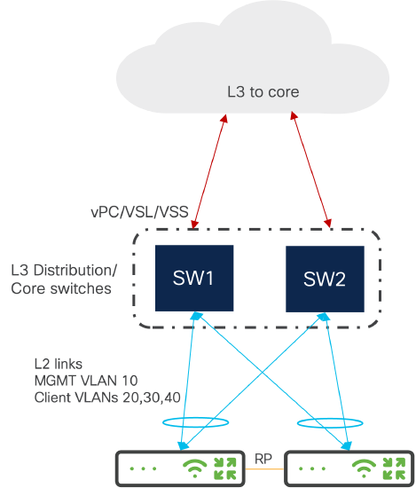
Two Campus Gateway Cluster in One DC
- Cross-connect the uplinks to a single logical distribution switch (vPC, VSL, etc.) to prioritize redundancy while maintaining adequate throughput during switch failure
- If maximum throughput is required, connect each Campus Gateway's uplinks to unique switches in the stack (for example, CG1 to SW1 and CG2 to SW2)
- RP ports can be directly connected or connected through the upstream switch with L2 VLANs
- On the upstream switch, configure two unique EtherChannels (one for each Campus Gateway) using LACP with trunking enabled and the corresponding list of allowed VLANs
Two Campus Gateway Cluster Across DCs

- Recommended when increased redundancy is needed (for example, the cluster is split between different buildings, areas of the data center on different power distributions, or different data centers)
- Inter-DC connections must be Layer 2 to allow Management VLANs, client VLANs, and RP VLAN to be shared
- If distance allows, the two Campus Gateways' RP link can be directly connected

Quality of Service (QoS)
Control Plane (CP) QoS
QUIC Tunnel traffic is marked with DSCP = CS6.
Data Plane (DP) QoS
For client traffic, Network Based Application Recognition (NBAR) runs on the AP, recognizing and classifying traffic at the AP level. Any client QoS policy is implemented at the AP.
Campus Gateway supports the "DSCP trust" QoS model:
-
Upstream (at the AP): The DSCP value is copied to the outer header of the VXLAN packet.
-
Downstream (at the Campus Gateway): The Campus Gateway does not enforce any QoS policy, as it trusts the client DSCP. The policy is applied only at the AP.

If a policy is in place (for example, rate limiting or DSCP remarking), the AP applies the policy. The Campus Gateway passes the DSCP value unchanged (assuming no additional QoS policies are applied).
For Wireless QoS configuration, refer to: Wireless QoS and Fast Lane
Broadcast and multicast traffic suppression
Broadcast Traffic: When deployed, Campus Gateway will block all broadcast traffic going downstream destined to wireless clients (wired to wireless) with the exception of few packet types:
- ARP
- DHCP/DCHPv6
- IPv6 NS/NA
When forwarding the allowed packets, the traffic will only be sent to the AP where the client is connected to.
Multicast Traffic: When Campus Gateway is deployed, all multcast traffic will be dropped with the exception of active mDNS queries and mDNS service advertisements when mDNS Gateway is configured.
mDNS Gateway
How is mDNS traffic handled by Campus Gateway?
At launch, Campus Gateway supports two mDNS modes:
|
Mode |
Behavior |
|
mDNS Drop |
All mDNS packets sourced from clients are dropped by Campus Gateway. This is the default mode if mDNS Gateway is not enabled. |
|
mDNS Gateway |
mDNS packets sourced from clients on Campus Gateway's wireless client VLANs are cached by Campus Gateway. The Campus Gateway unicasts back cached mDNS services in response to mDNS queries from clients connected to tunneled SSIDs. |
By default, Campus Gateway will be in mDNS drop mode. In order for any mDNS services to be shared across VLANs, mDNS gateway will need to be enabled for the SSID tunneling to Campus Gateway.
Note: mDNS bridging functionality is not available for Campus Gateway at this time.
Why mDNS Gateway?
The mDNS gateway provides an efficient and scalable way to share mDNS services between clients across different VLANs. Instead of continuously broadcasting mDNS services over the air (which consumes airtime), services are cached by Campus Gateway. The Campus Gateway unicasts back the response to mDNS queries, so services are only sent to clients that request them.
How mDNS Gateway Works:
-
When a client advertises its mDNS capabilities, the AP encapsulates the mDNS payload within the VXLAN packet.
-
Campus Gateway de-encapsulates the VXLAN packet and stores the mDNS PTR record.
-
When a client sends an mDNS query, Campus Gateway unicasts back the mDNS response payload to the client through the VXLAN tunnel to the AP the client is connected to.

Example: A querying client laptop is on the Corp SSID (VLAN 10). An advertising Printer A is on the IoT SSID (VLAN 20). When Printer A advertises its printer capabilities using mDNS, Campus Gateway caches the service. When the laptop sends an mDNS query for available printers, Campus Gateway responds with all cached mDNS printer services, allowing the laptop on VLAN 10 to discover Printer A on VLAN 20.

Policy-Based Filtering
mDNS Gateway supports policy-based filtering on each WLAN. Policy-based filtering defines which types of mDNS services should be learned and returned across VLANs. Only allowed services are cached and discoverable. Any service not in the allowed list is dropped. For example, if only AirPlay and Printers are allowed and a Chromecast mDNS advertisement is discovered, Campus Gateway drops those mDNS packets.
mDNS Gateway Specifications:
|
Parameter |
Value |
|
Scale |
20K unique service records (number of service providers + number of services) |
|
Time to Live (TTL) per service record |
4500 seconds |
Location Specific Services (LSS)
By default, Location Specific Services (LSS) is enabled whenever mDNS gateway is enabled, and users cannot disable it. LSS optimizes the mDNS gateway function by allowing clients to only receive mDNS services from clients connected to nearby access points.
The mDNS services returned in response to a client's query include only services from clients connected to the 24 strongest neighbor APs of the AP the querying client is associated to. Services from other APs are filtered out.
Example: When Laptop A queries for a printer, Printer A is associated to an AP in the list of 24 strongest neighbors of Laptop A's AP, so it is discovered. Printer B, associated to an AP not in the list of strongest neighbors, is not discovered.

WPN support
For WPN to operate with mDNS traffic, mDNS gateway must be enabled. When Campus Gateway receives the mDNS advertisement from the client, it also receives the UDN ID used for WPN after the VXLAN tunnel is de-encapsulated. The Campus Gateway stores the mDNS service along with the corresponding UDN ID of the advertising client. When a client sends an mDNS query, the Campus Gateway unicasts back a response with the mDNS service only if the UDN ID of the querying client matches the UDN ID of the stored services.

Monitoring and reporting
Tools and Methods for Monitoring the Architecture:
Cisco Meraki dashboard for cloud-based monitoring and management of both APs and Campus Gateway devices
Reporting and Analytics Tools:
Campus Gateway Local Status Page allows for local monitoring of the device as well as to generate debug bundles for troubleshooting with Meraki Support.
Additional resources