
Campus Gateway Installation Guide
Overview
The Cisco Campus Gateway is a cloud-native solution from Cisco designed for centralized wireless deployments. It functions similarly to a wireless LAN controller (WLC): data plane traffic is tunneled from the access points (APs) to the Campus Gateway, where it is terminated and switched to the rest of the network. By terminating traffic centrally, client VLANs only need to exist in the core, which enables seamless roaming across Layer 3 (L3) domains of the APs.
Campus Gateway uses the same hardware as its WLC counterpart (for example, CW9800H1-MCG shares the same hardware as the CW9800H1 WLC) but leverages a different, cloud-native managed architecture. In this architecture, each device is directly managed by the Meraki dashboard. Each device maintains its own individual Meraki Tunnel to the dashboard. Refer to documentation in the Campus Gateway Design and Best Practice Guide.

Package contents
|
Model |
Contents |
|
CW9800H1-MCG |
|
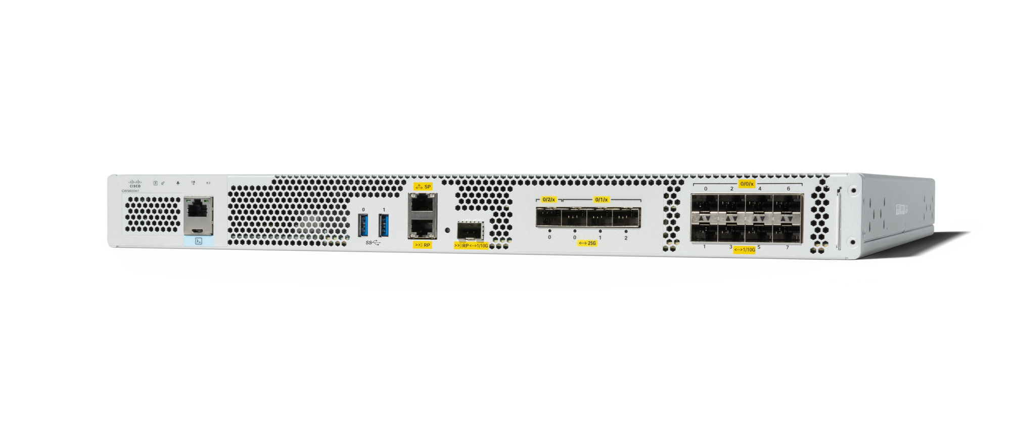
Front panel

|
Label |
Description |
|
1 |
PWR — Power LED |
|
2 |
SYS — System LED |
|
3 |
ALM — Alarm LED |
|
4 |
HA — High-Availability LED |
|
5 |
M.2 SSD |
|
6 |
RJ-45 compatible console port (Not available for use on Campus Gateway) |
|
7 |
USB Port 0 (Not available for use on Campus Gateway) |
|
8 |
USB Port 1 (Not available for use on Campus Gateway) |
|
9 |
SP — RJ-45 1-GE management port |
|
10 |
RP — 1/10-GE SFP+ port |
|
11 |
TwentyFiveGigE0/2/0 — 25-GE SFP28 EPA2 Port 0 |
|
12 |
TwentyFiveGigE0/1/0 — 25-GE SFP28 EPA1 Port 0 |
|
13 |
TwentyFiveGigE0/1/1 — 25-GE SFP28 EPA1 Port 1 |
|
14 |
TwentyFiveGigE0/1/2 — 25-GE SFP28 EPA1 Port 2 |
|
15 |
Te0/0/0 — 1-GE SFP / 10-GE SFP+ Port 0 |
|
16 |
Te0/0/2 — 1-GE SFP / 10-GE SFP+ Port 2 |
|
17 |
Te0/0/4 — 1-GE SFP / 10-GE SFP+ Port 4 |
|
18 |
Te0/0/6 — 1-GE SFP / 10-GE SFP+ Port 6 |
|
19 |
Carrier Label Tray |
|
20 |
Te0/0/7 — 1-GE SFP / 10-GE SFP+ Port 7 |
|
21 |
Te0/0/5 — 1-GE SFP / 10-GE SFP+ Port 5 |
|
22 |
Te0/0/3 — 1-GE SFP / 10-GE SFP+ Port 3 |
|
23 |
Te0/0/1 — 1-GE SFP / 10-GE SFP+ Port 1 |
|
24 |
RP — RJ-45 1-GE redundancy port |
|
25 |
CON — 5-pin Micro-B USB console port (Not available for use on Campus Gateway) |
Built-in SFP and SFP+ ports
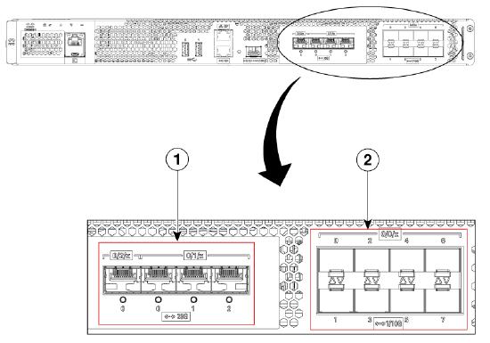
Image reference “1”
Bay 1 — 3 x 25-GE SFP28 ports:
|
Port |
Description |
|
TwentyFiveGigE0/1/0 |
25-GE SFP28 Port 0 |
|
TwentyFiveGigE0/1/1 |
25-GE SFP28 Port 1 |
|
TwentyFiveGigE0/1/2 |
25-GE SFP28 Port 2 |
Bay 2 — 1 x 25-GE SFP28 port:
|
Port |
Description |
|
TwentyFiveGigE0/2/0 |
25-GE SFP28 Port 0 |
Image reference “2”
Bay 0 — 8 x 1-GE/10-GE SFP+ ports:
|
Port |
Description |
|
Te0/0/0 |
1-GE SFP / 10-GE SFP+ Port 0 |
|
Te0/0/1 |
1-GE SFP / 10-GE SFP+ Port 1 |
|
Te0/0/2 |
1-GE SFP / 10-GE SFP+ Port 2 |
|
Te0/0/3 |
1-GE SFP / 10-GE SFP+ Port 3 |
|
Te0/0/4 |
1-GE SFP / 10-GE SFP+ Port 4 |
|
Te0/0/5 |
1-GE SFP / 10-GE SFP+ Port 5 |
|
Te0/0/6 |
1-GE SFP / 10-GE SFP+ Port 6 |
|
Te0/0/7 |
1-GE SFP / 10-GE SFP+ Port 7 |
Supported SFP modules
Small Form-Factor Pluggable (SFP) supported modules:
- GLC-LH-SMD
- GLC-SX-MMD
- GLC-TE
- GLC-ZX-SMD
- GLC-BX-U
- GLC-BX-D
- GLC-EX-SMD
Enhanced Small Form-Factor Pluggable (SFP+ / SFP28) supported modules
- SFP-10G-SR
- SFP-10G-SR-S
- SFP-10G-LR
- SFP-10G-LR-X
- SFP-10G-ER
- SFP-H10GB-ACU10M
- SFP-H10GB-CU5M
- SFP-10G-AOC10M
- Finisar-LR (FTLX1471D3BCL)
- Finisar-SR (FTLX8574D3BC)
- SFP-H10GB-CU1M
- SFP-H10GB-CU1-5M
- SFP-H10GB-CU2M
- SFP-H10GB-CU2-5M
- SFP-H10GB-CU3M
- SFP-H10GB-ACU7M
- SFP-10G-AOC1M
- SFP-10G-AOC2M
- SFP-10G-AOC3M
- SFP-10G-AOC5M
- SFP-10G-AOC7M
- SFP-10/25G-CSR-S (Only supported in the 25-GE ports)
- SFP-10/25G-LR-S (Only supported in the 25-GE ports)
- SFP-25G-SR-S
- SFP-25G-AOC2M
- SFP-25G-AOC10M
- SFP-25G-AOC5M
- SFP-H25G-CU1M
- SFP-H25G-CU5M
- SFP-25G-AOC3M
- SFP-25G-AOC7M
- SFP-25G-AOC1M
Supported redundancy port SFP modules
SFP/SFP+ Modules:
- GLC-LH-SMD
- GLC-SX-MMD
- SFP-10G-SR
- SFP-10G-SR-S
- SFP-10G-LR
- SFP-10G-LR-S
Pre-installation preparation
Check and set firmware
Refer to the Upgrade software section of the deployment guide for instructions specific to the Campus Gateway. Also refer to the Managing Firmware Upgrades documentation for general information.
Configure upstream network
For information on the network configuration, refer to the section the Network requirements section in the Campus Gateway Deployment Guide.
Check and configure firewall settings
If a firewall is in place, refer to steps to the Configure upstream firewall settings section in the Campus Gateway Deployment Guide.
Safety and Warnings
-
The equipment is intended for industrial or other commercial activities.
-
The equipment is designed for use in areas without exposure to harmful and dangerous production factors, unless otherwise specified in the operational documentation and/or on the equipment labeling.
-
The equipment is not for domestic use and is not to be used without the presence of maintenance personnel.
-
The equipment must be installed and maintained by specialists with the appropriate qualifications, sufficient specialized knowledge, and skills.
-
Rules and conditions for the sale of equipment are determined by the terms of contracts concluded by Cisco or authorized Cisco partners with equipment buyers.
-
Disposal of the device at the end of its service life should be carried out in accordance with all applicable state regulations and laws. Do not throw the device in with household waste. The equipment is subject to storage and disposal in accordance with the organization's disposal procedure.
-
The equipment should be stored in its original packaging in a room protected from atmospheric precipitation. The permissible temperature and humidity ranges during storage are specified in the Operation (Installation) Manual.
-
Transportation of equipment should be carried out in the original packaging in covered vehicles by any means of transport. The temperature and humidity during transportation must comply with the permissible ranges specified in the Operation (Installation) Manual.
Installation instructions and initial setup
Physical mounting
To mount the Campus Gateway chassis, follow the CW9800H1 installation instructions available here:
Cisco Catalyst CW9800H1 and CW9800H2 Wireless Controllers Hardware Installation Guide
Configure your network in the Meraki dashboard
- Create a dashboard account and organization if you do not already have one.
- Add the Campus Gateway device to your dashboard network.
- For detailed instructions, refer to the Creating a dashboard Account and Organization document and the Adding and Removing Devices from dashboard Networks document.
Uplink switchport connections
For the initial boot and dashboard registration, it is critical to connect the Campus Gateway to a switch correctly. Follow these steps:
- Connect the Campus Gateway to a switch via at least one port configured as an 802.1Q trunk with at least one active VLAN.
- The VLAN must provide an IPv4 DHCP address to the Campus Gateway along with related DNS servers so it can automatically reach dashboard.
- This VLAN with active DHCP can be an 802.1Q tagged VLAN or the native VLAN on the trunk port.
- Once the Campus Gateway is configured through the cluster onboarding flow<PLACEHOLDER link to onboarding flow section on deployement guide>, you can change the Campus Gateway 's IP address to a static IP in the same or different VLAN.
- It is recommended to use an 802.1Q tagged VLAN to carry management and client traffic.
- At least 2 ports are recommended for the Campus Gateway-to-upstream-switch connections.
Note: IPv6 for the Campus Gateway interfaces is not supported at MVP. Ensure an IPv4 address is provided.
By default, when the Campus Gateway boots up, all ports (4x25G and 8x10G) are configured in a single port-channel. Before wiring the Campus Gateway to the network, the ports on the upstream switch must be configured in a port-channel to allow the Campus Gateway to come up.
Use only ports of the same speed and type to connect to the switch etherchannel — either all 10GE or all 25GE ports.
Power the Campus Gateway
Refer to the CW9800H1 hardware installation guide for detailed power-up instructions.
LED indicators and status
System LED status table
|
# |
System Status |
Power LED |
dashboard Status LED |
System LED |
Alarm LED |
|
1 |
Campus Gateway is powered off or not receiving power. |
Off |
Off |
Off |
Off |
|
2 |
Campus Gateway is powered on and is loading the bootstrap firmware. |
Solid Green |
No change |
No change |
Solid Amber: ROMMON boot |
|
3 |
ROMMON boot complete. |
No change |
No change |
No change |
Solid Green |
|
4 |
Campus Gateway is loading the operating system. |
No change |
No change |
Slow Blinking Green |
Solid Amber: SYSTEM bootup |
|
5 |
Boot up fails; device in ROMMON. |
No change |
No change |
Solid Amber (Crash) / Slow Blinking Amber (Secure boot failure) |
Slow Blinking Amber: Temperature Error & Secure boot failure |
|
6 |
System error: Campus Gateway failed to load operating system or bootstrap firmware. |
No change |
No change |
Solid Amber (Crash) / Slow Blinking Amber (Secure boot failure) |
Slow Blinking Amber: Temperature Error & Secure boot failure |
|
7 |
Setting up local management and cloud-connectivity requirements. Note: If the Campus Gateway has not been assigned a static management IP previously, it will try to obtain an IP via DHCP in this stage. |
No change |
Slow Blinking Amber |
No change |
No change |
|
8 |
System error: Campus Gateway failed to complete local provisioning. |
No change |
Solid Amber |
No change |
No change |
|
9 |
Campus Gateway is completely provisioned but unable to connect to Meraki cloud. |
No change |
Solid Amber |
No change |
No change |
|
10 |
Firmware download / upgrade in progress. |
No change |
Blinking Green: System upgrade in progress |
No change |
No change |
|
12 |
Campus Gateway is fully operational and connected to the Meraki cloud. |
Solid Green |
Solid Green |
No change |
No change |
|
13 |
Operating System boot complete. |
No change |
No change |
Solid green |
No change |
|
14 |
Factory Reset via the Local Status Page. |
No change |
No change |
Slow Blinking Red |
No change |
|
15 |
Blink LED Feature. |
No change |
Fast Blinking Red |
Fast Blinking Red |
Fast Blinking Red |
Assigning an IP address
Assign IP addresses
The Campus Gateway supports both DHCP-based and static IP address assignment:
-
DHCP (default): After initial boot, the Campus Gateway uses Meraki auto-uplink logic to detect available VLANs on the trunk port and selects one with internet connectivity. It uses DHCP on the selected VLAN to obtain an IP address and automatically connects to dashboard.
-
Static IP: Once the Campus Gateway is configured via the cluster onboarding flow, you can change the Campus Gateway's IP address to a static IP in the same or a different VLAN via dashboard or the Local Status Page (LSP).
Note: IPv6 for the Campus Gateway interfaces is not supported at MVP. It is important to provide an IPv4 address.
Uplink auto configuration
How does Campus Gateway reach dashboard initially?
After initial boot, Campus Gateway uses the Meraki auto-uplink logic to determine one active VLAN for connecting to dashboard. The Campus Gateway detects the available VLANs on the trunk port and chooses one with internet connectivity. Campus Gateway uses DHCP on the selected VLAN to get an IP address and automatically connects to dashboard.
For auto-uplink to work, ensure the following:
- The uplink switch is configured correctly (port-channel and trunk).
- DHCP is active on at least one VLAN with a default gateway and DNS server.
- Connectivity to dashboard is allowed on the active VLAN.
Once the Campus Gateway connects to dashboard and is configured with the required connectivity information, it fetches the onboarding configuration and uses the IP address information pushed from dashboard going forward.
Manually configuring the uplink
If connectivity between the Campus Gateway and dashboard is lost or cannot be established, the Local Status Page (LSP) can be used to manually configure parameters such as the uplink ports' VLAN, IP address, or DNS settings to restore connectivity.
For more information refer to the Connecting to the Local Status Page section in the Campus Gateway Deployment Guide.
Note: If the Campus Gateway is unable to reach dashboard even when using the LSP, please contact Meraki Support.
Deploying Campus Gateway and adding to a network
Refer to the Deployment procedure steps section in the Campus Gateway Deployment Guide for instructions.
Warranty
Campus Gateway warranty coverage periods are as follows:
|
Product |
Time Period |
Comments |
|
CW9800H1-MCG |
1 Year |
1 Year Warranty with next-day replacement included. |
|
Campus Gateway Accessories (SFP Modules, twinax/SFP+ cables, all mounting kits and stands, additional power cords) |
1 Year |
Standard 1-year accessory warranty. |
Note: The above table is a general guideline for warranty terms and is not final. Warranty terms are subject to printed warranty information on the online Meraki Returns and Policy section.
Support and additional information
If issues are encountered with device installation or additional help is required, contact Meraki Support by:
- Logging in to dashboard.meraki.com.
- Opening a case by visiting the Get Help section.