
Capturing Traffic on Multiple Interfaces
When troubleshooting problems on the network, it is important to try and isolate any hardware that is not handling traffic appropriately. Dashboard's built-in packet capture tool can be used to observe multiple interfaces of a device and see if traffic is flowing through as expected. Simultaneous packet captures on multiple ports are useful because they allow the user to see a more complete picture of how traffic is flowing.
This article explains how to capture traffic simultaneously on multiple interfaces of a Meraki device, and how to analyze that traffic to detect potential issues.
The MS switch does not support multiple simultaneous captures, but instead allows a single capture to span multiple ports. Please refer to our packet capture documentation for more info.
Capturing Traffic
- Open two web browser tabs or windows.
- In each tab or window:
- In Dashboard, navigate to Network-wide > Packet capture.
- Select the appropriate device type from the top drop-down menu:

- Select the device to take the capture on.
- Select the appropriate Interface for each capture. For MR devices, this will generally be Wired in one window and Wireless in the other. For MX devices, this will generally be LAN in one window and Internet in the other.
- Change the Output to Download .pcap file (for Wireshark):

- Set the duration for the capture. 60 seconds is usually sufficient.
- Fill in each File name field with a descriptive name, like "LAN" or "Internet". This will make it easy to identify which interface the capture was taken on.
- When you are ready to begin capturing traffic, click Start capture on both windows. You may be prompted to specify a download location.
Analyzing Traffic
The following sections describe how simultaneous captures on either an MR access point or MX security appliance can be used to identify problems on the network.
Wired and Wireless Traffic on an MR Access Point
Capturing traffic on both the wired and wireless interfaces of an MR access point can help isolate the source of a network problem. For example, if a client can connect to an MR access point but cannot obtain an address via DHCP, it may be unclear whether the issue is being caused by the AP or the DHCP server.
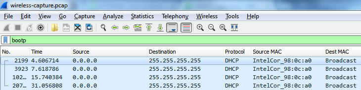
Comparing the wired and wireless captures can reveal whether the AP is correctly receiving and forwarding the client's DHCP requests. The wireless capture below shows that the client is sending DHCP DISCOVER messages to the AP, but is not receiving a response:
The wired capture below shows that the same DHCP DISCOVER messages are being sent out onto the LAN, but are still not receiving a response:
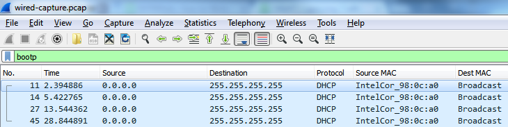
These captures show that the AP is forwarding traffic correctly, but no response is coming from the DHCP server. Based on these results, it is likely that the issue resides on the LAN or DHCP server.
WAN and LAN Traffic on an MX Security Appliance
Capturing traffic on both the LAN and WAN interfaces of an MX security appliance can help isolate the source of a network problem. For example, if a server on the LAN has a 1:1 NAT rule but is not responding to pings from clients on the internet, it may be unclear whether the issue is being caused by an improperly configured 1:1 NAT rule or an issue with the server.
Comparing the LAN and WAN captures can reveal whether the appliance is functioning properly. In the example below, the MX is configured with a 1:1 NAT rule that accepts inbound traffic on 104.17.32.2, and forwards that traffic to the server at 192.168.128.29. The WAN-side capture below shows that a client at 66.74.83.217 is attempting to ping this server, but is not receiving a response:

The LAN-side capture below shows that the ping requests are being correctly forwarded to the server at 192.168.128.29, but are not receiving a response.

These captures show that the appliance's 1:1 NAT rule is forwarding traffic correctly, but no response is coming from the local server. Based on these results, it is likely that the issue resides on the LAN or local server.