
Scaling MX Architectures
Overview
This document will go over general reference architectures for horizontally scaling MX for different scenarios. These scenarios cover both MX running in VPN concentrator mode as well as MX operating in routed mode at the edge of the network.
Routed Mode Architectures
This example assumes two MX appliances running at the edge of a network but can be further extended using the same design for as many MX appliances as needed.
Active-Active Routed Mode MX Scaling (Outbound Only)
Topology
The core component to this topology is that there must be a switch downstream of the MX security appliances such as a Cisco Catalyst 9300 or Nexus switch which supports the following capabilities:
- Source based routing (PbR)
- IP SLA
- CEF (or another mechanism like CEF to do equal cost load balancing across multiple default routes)
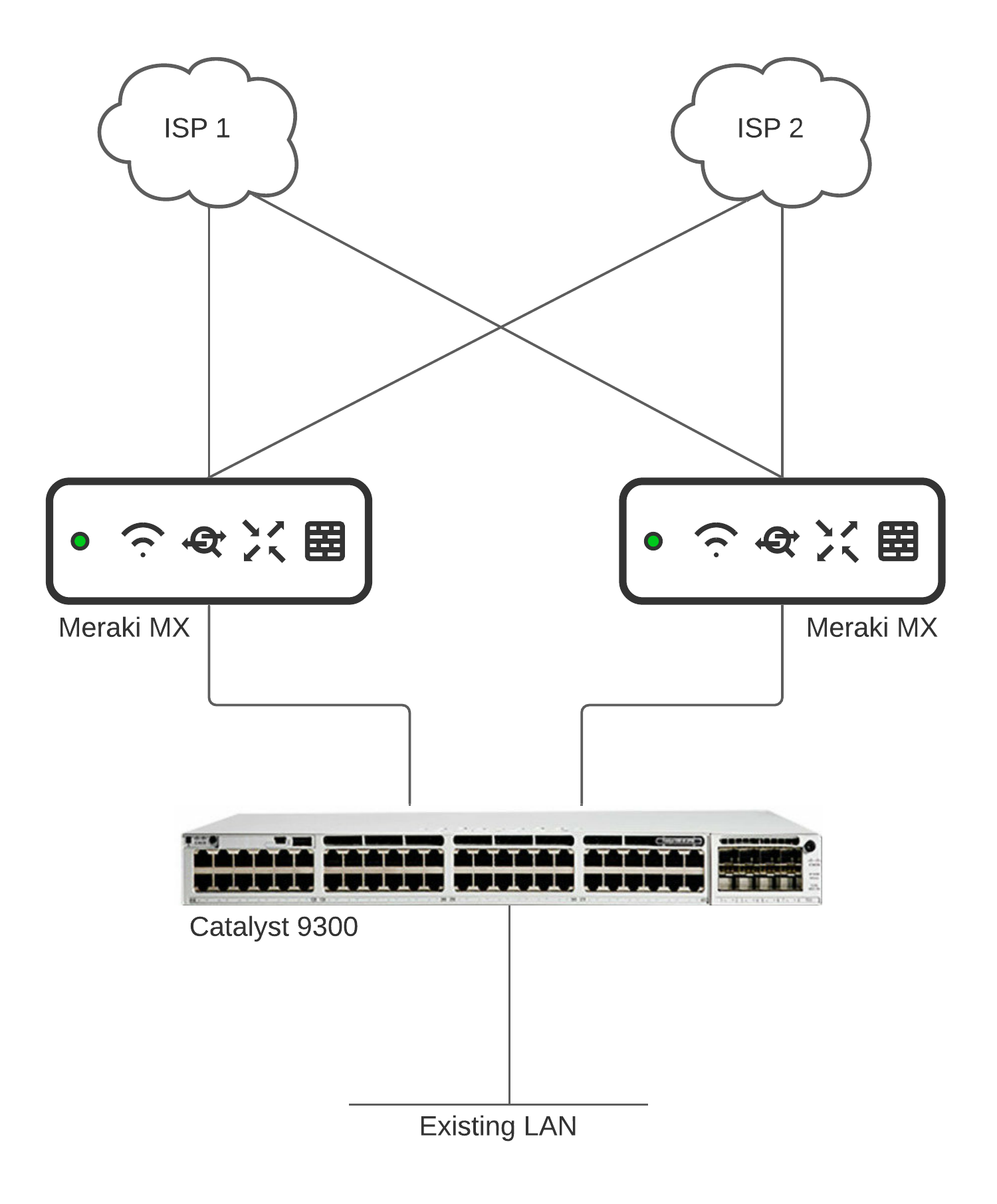
Physical Setup
In the above setup each MX at the edge will be running in routed mode with one or more WAN uplinks connected. On the LAN side there will be one link from each MX towards the switch (a Cisco Catalyst 9300 in this case).
We cannot use STP or etherchannel between the MX and switch as we need to use routed ports on the switch interface.
On the downstream side of the switch, the rest of the network will be connected just as it normally is.
Sample Configuration
The below Catalyst/IOS configurations are intended for reference only. For assistance with configuration of the C9300 please reach out to your Cisco SE or contact Cisco TAC.
The following two solutions cover a high level overview of how you can leverage source based routing or CEF technologies coupled with IP SLA for failover to load balance LAN traffic to multiple MX hubs at the organizations edge. Both examples are referencing a Cisco Catalyst 9300 switch but could be done with others as well as long as they meet the requirements listed above.
Baseline Configuration
The baseline configuration comprises that which is needed for either solution 1 or solution 2 listed below.
Start with creating an interconnect VLAN to use for routing between the MX and switch and assign it to the port connected to the switch from the hardware setup step above.
MX Addressing and VLANs Configuration
MX-1 Example:
IP: 192.168.0.1
Subnet: 192.168.0.0/252
VLAN: 10
Port 3: Access VLAN 10
MX-2 Example:
IP: 192.168.0.5
Subnet: 192.168.0.4/252
VLAN 11
Port 3: Access VLAN 11
Switch Uplink Configuration
Next configure the corresponding addressing on the switch interfaces that uplink to each MX.
Uplink to MX-1 Example:
IP: 192.168.0.2
Subnet: 255.255.255.252
Uplink to MX-2 Example:
IP: 192.168.0.6
Subnet: 255.255.255.252
Static Routes
Each MX will have a static route pointing to the switch to get return traffic back to the LAN. In this example we will assume all LAN subnets can be summarized by 10.0.0.0/8.
MX-1 Example:
Static route 10.0.0.0/8
Next Hop: 192.168.0.2
Always Active
MX-2 Example
Static route 10.0.0.0/8
Next Hop: 192.168.0.6
Always Active
The switch will also need a default route for each MX pointing to the corresponding MX IP configured above
Example:
ip route 0.0.0.0 0.0.0.0 192.168.0.1
ip route 0.0.0.0 0.0.0.0 192.168.0.5
IP SLA Tracking
We will also add an IP SLA tracking object to monitor the upstream path through each MX to ensure there is internet reachability and failover our source routes or CEF routes below if a particular MX goes offline.
We will first add a route for 8.8.8.8 and 8.8.4.4 pointing to one MX respectively. If additional MXs are added, additional IP's/static routes and corresponding IP SLA object's will need to be added following the below pointing to those additional MX's as the next hop. These are used in our IP SLA tracking below for failover.
Example:
ip route 8.8.8.8 255.255.255.255 192.168.0.1
ip route 8.8.4.4 255.255.255.255 192.168.0.5
Next we can create the IP SLA tracking object which utilizes these routes.
SLA1 to MX-1 Example Configuration:
ip sla 1
icmp-echo 8.8.8.8 source-ip 192.168.0.3
frequency 5
threshold 100
ip sla schedule 1 life forever start-time now
track 1 ip sla 1
delay down 10 up 10
SLA2 to MX-2 Example Configuration:
ip sla 2
icmp-echo 8.8.4.4 source-ip 192.168.0.5
frequency 5
threshold 100
ip sla schedule 2 life forever start-time now
track 2 ip sla 2
delay down 10 up 10
Switch SVI's and VLANs
Next, create any of the L3 networks/SVI's that the rest of the LAN network needs based on your network design and requirements. In our example, the LAN downstream of the switch will utilize two VLANs; 20 and 30.
Example Configuration:
interface vlan 20
ip address 10.0.20.1
subnet 255.255.255.0
interface vlan 30
ip address 10.0.30.1
subnet 255.255.255.0
Solution 1 - Source Routing with IP SLA
This solution leverages source based routing with IP SLA for tracking to balance VLANs across multiple MX appliances. In this deployment model, one or more VLANs would be steered to a specific MX while additional sets of VLANs would be steered to other MX appliances to balance the traffic across different MX appliances.
If you have only one VLAN then this solution would not work as all traffic would be steered to only one MX. In this case, please see solution 2 below.
The following configuration is just an example of how you could configure source based routing with IP SLA on a Catalyst 9300 switch to load balance VLANs across different MX appliances.
Access List Configuration
First we will define an access list to match each vlan that we want to route to a different MX.
VLAN 20 Example:
access-list 1 permit ip 10.0.20.0 0.0.0.255
VLAN 30 Example:
access-list 2 permit ip 10.0.30.0 0.0.0.255
Route Map Configuration
Next we need to create a route map using the access lists above so that traffic for each VLAN can be steered towards each MX. In the match statements of the route map we will direct traffic for VLAN 20 towards MX-1 first and in the event MX-1 fails, we will route VLAN 20 to MX-2 instead. The second match statement will do the inverse for VLAN 30 routing it to MX-2 first and in the event it fails, route VLAN 30 to MX-1.
Example:
route-map OUTBOUND_TRAFFIC permit 10
match ip address 1
set ip next-hop verify-availability 192.168.0.1 10 track 1
set ip next-hop verify-availability 192.168.0.5 20 track 2
route-map OUTBOUND_TRAFFIC permit 20
match ip address 2
set ip next-hop verify-availability 192.168.0.5 10 track 2
set ip next-hop verify-availability 192.168.0.1 20 track 1
Apply Route Map to SVI
The final step is to apply the route map to the SVI's.
Example:
interface vlan 20
ip policy route-map OUTBOUND_TRAFFIC
interface vlan 30
ip policy route-map OUTBOUND_TRAFFIC
Solution 2 - CEF with IP SLA
Solution 2 is very similar to solution 1 but relies on the CEF load balancing algorithm to route traffic upstream. Once the baseline configuration above is completed, enabling CEF-based balancing is very simple.
Configuration
The following configuration is just an example of how you could configure CEF with IP SLA on a Catalyst 9300 switch to load balance all traffic across different MX appliances.
First we add our IP SLA tracking object to both of the default routes configured above. Both of these default routes have the same AD so traffic will be load balanced between the two automatically without the complexity of PbR as in solution 1:
Example:
ip route 0.0.0.0 0.0.0.0 192.168.0.1 track 1
ip route 0.0.0.0 0.0.0.0 192.168.0.5 track 2
The final step is to enable CEF load sharing using the following:
ip cef load-sharing algorithm universal include-ports source destination
Active-Active Routed Mode MX Scaling (Inbound & Outbound)
The above topology is only for scaling MX for outbound traffic flows. If you also require DMZ/inbound services (ex. port forwarding, 1:1 NAT, 1:Many NAT) to access resources such as internal servers then an additional HA pair should be added to specifically handle this inbound/DMZ traffic. The LAN side of this HA pair could be any switching infrastructure such as a Meraki MS and is where resources such as a server farm could reside. The benefit of this segmentation is that the inbound/DMZ services will not be subjected to any increased load from clients accessing the internet. For details on configuring the HA pair please refer to this MX HA Deployment Guide document.
Topology
.png?revision=1&size=bestfit&width=835&height=586)