
MX Warm Spare - High-Availability Pair
MX Warm Spare Overview
This page describes how to set up a high-availability (HA) pair using Virtual Router Redundancy Protocol (VRRP) between two MX security appliances. The setup includes either one-arm concentrator mode or routed mode, as well as the expected behavior of the HA pairs. High availability can be used to minimize downtime in the event of a hardware failure.
Only one license is required for an HA pair, so the warm spare unit does not require a separate license. Alerts for warm spare failover can be configured on the Network-wide > Configure > Alerts page.
Note: The spare MX must be the same MX model as the primary. Warm spare functionality is not supported between different MX models (for example, MX85 and MX105) and also MXs with the same model but different territorial designations (e.g., MX67C-WW and MX67C-NA).

The swap button changes the primary and spare roles of the two MX devices and is not meant to test HA failover. For a failover test, you must completely disconnect the uplink to the primary MX.
While DDNS is enabled, if the Primary MX goes offline and will fail over to the Secondary for an extended period, it is recommended that you perform a swap of the Secondary MX to the Primary. This will prevent any issues with DDNS updates while the original primary is offline.
For more information about DDNS, refer to the documentation below:
Use Case and Benefits
In most customer deployments, network downtime has a direct impact on the business and should be avoided to prevent service interruptions. Warm spare functionality prevents the network from having a single point of failure, allowing for fast, automatic recovery in the event of device failure. This functionality not only reduces the negative impact on end-user services but also offers significant benefits:
-
Reduced Network Downtime: In the event of hardware failure, network downtime will be greatly reduced or eliminated entirely, depending on the architecture being used.
-
No Manual Intervention Required: There is no need for manual intervention by the network administration team to facilitate recovery from a hardware failure.
-
Zero-Downtime MX Upgrades: When MX appliances are configured to operate in HA (High Availability), the dashboard will automatically take steps to minimize downtime during upgrades. This is achieved through the automated process detailed in the "Appliance Network with Two MXs in an HA Configuration" section of the "Best Practices for Meraki Firmware" document.
Terminology
For purposes of this document, it is important to understand the following terms and their meaning:
Primary: The MX that is configured as the main MX for the network. If both MXs are online, this is the MX that traffic should be flowing through. This is a static designation, meaning that regardless of the current state of the network, the primary will always be the primary.
Spare: The MX that is configured as the secondary MX for the network. If both MXs are online, this is the MX that is the inactive warm spare. This is a static designation, meaning that regardless of the current state of the network, the secondary will always be the secondary.
Active: The MX that is currently acting as the edge firewall/security appliance for the network. This is a dynamic designation.
Passive: The MX that is currently acting as an inactive warm spare with no traffic passing through it. This is a dynamic designation.
Dual active: Dual active describes a scenario in which both the primary and the spare are in the active state. This occurs when both MXs are online and communicating with the cloud, but the spare is not receiving heartbeat packets (see VRRP heartbeats in the next section) from the primary. This can cause several issues with dynamic DNS, VPN, and traffic processing in general and should be avoided at all costs. The Physical Architectures section of this document describes how to deploy an MX warm spare pair in order to minimize the chances of a dual active scenario occurring.
Underlying Concepts and Technologies
VRRP Heartbeats
Failure detection for an MX warm spare pair uses VRRP heartbeat packets. These heartbeat packets are sent from the primary MX to the spare MX on all configured VLANs in order to indicate that the primary is online and functioning properly. As long as the secondary is receiving these heartbeat packets, it functions in the spare state. If the secondary stops receiving these heartbeat packets for 3 seconds, it will assume that the primary is offline and will transition into the active state. When the MX is in routed mode, VRRP heartbeats are not sent over the WAN and there is no guarantee that the WAN interfaces can communicate with each other. See Connection Monitoring below to understand how the WAN interface can also impact how VRRP packets are sent through the LAN on routed mode.
For more in-depth information regarding the VRRP mechanics on the MX, please see the Routed HA Failover Behavior documentation.
Connection Monitoring
Connection monitor is an uplink monitoring engine built into every MX security appliance. The mechanics of the engine are described in the Connection Monitoring for WAN Failover article. When all uplinks of a primary MX are marked as failed by connection monitor, that MX will stop sending VRRP heartbeat packets, which will initiate a warm spare failover. Once there is at least one working uplink, the primary returns to a working state and resumes sending heartbeat packets and the secondary relinquishes the active role back to the primary.
DHCP Synchronization
The DHCP lease table synchronizes regularly between the primary and spare over UDP port 3483. Synchronization prevents a scenario where an IP address is assigned by the primary via DHCP, and then the same IP address is assigned to another client by the spare after a failover.
Dashboard Configuration
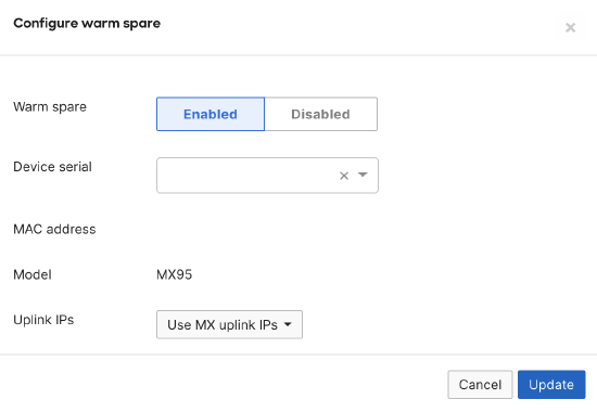
To configure warm spare failover for an existing dashboard network, navigate to the Security & SD-WAN > Monitor > Appliance status and select Configure warm spare near the upper-left side of the page, below the device name. In the window that appears, select Enabled. Enter the serial number of the secondary MX and select the desired uplink IP configuration, then select Update to enable warm spare.
.png?revision=1&size=bestfit&width=313&height=83)
Adding or replacing an online/offline spare MX in the dashboard network will cause a brief connectivity loss on the primary MX due to the initialization of the HA configuration.
Furthermore, when a warm spare is added to a network, you will lose the ability to use VLAN objects. Any existing L3 rules utilizing VLAN objects will be removed as VLAN objects are not compatible with Warm Spare.
Use MX uplink IPs: When using this option, the current active MX will use its distinct uplink IP or IPs when sending traffic out to the internet. This option does not require additional public IPs for internet-facing MXs, but also results in more disruptive failover. This is because the IP of the outbound flows on the MX will change, which will result in a need for clients to reestablish all live sessions (e.g. web pages, applications, etc).
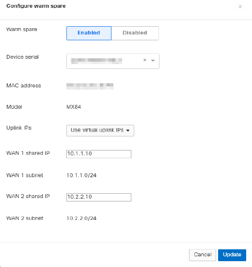
Use virtual uplink IPs: When using this option, both MXs will use a shared virtual IP (VIP) when sending traffic to the internet. This option requires an additional public IP per uplink, but allows for more seamless failover. This is because the IP address of the outbound flows on the MX will not change, meaning that during the failover client devices will not need to reestablish active sessions. The VIP for each uplink must be in the same subnet as the IPs of the MXs themselves. Also, the VIP must be different from both MX uplink IPs.
Regardless of which option is selected, both MX devices will need their own uplink IP addresses for dashboard connectivity.
Dashboard configuration should always be performed before the secondary MX is physically connected to the network.
Steps to configure secondary appliance:
-
Set up the WAN Static IP configuration on the Local Status Page of the secondary appliance (if required).
-
Power off the secondary appliance.
-
Cable the LAN and WAN connections as per the recommended topology and power on secondary appliance.
Note: When an MX is added to a network that already contains an MX of the same model from the Organization > Configure > Inventory page, the MX will automatically be added to that network in warm spare mode.
Note: MXs operating in HA cannot have more than 255 VLANs configured.
MX Mode Options for Warm Spare Configuration
MX devices can be configured in a high-availability pair (warm spare) using one of two MX addressing options (Security & SD-WAN > Configure > Addressing & VLANs):
- Passthrough or VPN Concentrator mode
- Routed mode
Note: While the mode is reflected in the dashboard as Passthrough or VPN Concentrator mode, the MX only supports a one-armed concentrator topology for this mode. Additional information regarding this can be found in the Connecting the MXs in a “One-Armed” VPN Concentrator Pair section.
Each mode will result in having two MXs on the same network, with a primary able to failover to a secondary. However, each mode requires a slightly different configuration, both detailed in the Addressing and VLANs section. If you need more information about the MX addressing modes or how to select which one is best for your deployment, refer to our MX Addressing and VLANs article.
VPN Concentrator Warm Spare
Concentrator warm spare is used to provide high availability for a Meraki Auto VPN head-end appliance.
Network Setup
Each concentrator has its own IP address to exchange management traffic with the Meraki cloud controller. However, the concentrators also share a virtual IP address that is used for non-management communication.
Connecting the MXs in a “One-Armed” VPN Concentrator Pair
Before deploying MXs as one-arm VPN concentrators, place them into Passthrough or VPN Concentrator mode on the MX Addressing and VLANs page. In one-armed VPN concentrator mode, the units in the pair are connected to the network only via their respective Internet ports. Make sure they are not connected directly via their LAN ports. They must be within the same IP subnet and able to communicate with each other, as well as with the Cisco Meraki dashboard. Only VPN traffic is routed to the MX, and both ingress and egress packets are sent through the same interface.
Virtual IP
The virtual IP (VIP) is shared by both the primary and warm spare VPN concentrator. VPN traffic is sent to the VIP rather than the physical IP addresses of the individual concentrators. The virtual IP is configured by navigating to Security & SD-WAN > Monitor > Appliance status when a warm spare is configured. It must be in the same subnet as the IP addresses of both appliances, and it must be unique. In particular, it cannot be the same as either the primary or warm spare's IP address.
Failure Detection
The two concentrators share health information over the network via the VRRP protocol.
In the event that the primary unit or connectivity tests for its WAN fail, the warm spare will assume the primary role until the original primary is back online or is passing connectivity tests again. When the primary VPN concentrator is back online and the spare begins receiving VRRP heartbeats again, the warm spare concentrator will relinquish the active role back to the primary concentrator.
The total time for failure detection, failover to the warm spare concentrator, and ability to start processing VPN packets is typically less than 30 seconds.
Routed Warm Spare
Routed warm spare is used to provide redundancy for internet connectivity and appliance services when an MX security appliance is being used as a routed gateway.
WAN Virtual IPs
VIP addresses are shared by both the primary and warm spare appliance. Inbound and outbound traffic use this address to maintain the same IP address during a failover and reduce disruption. The virtual IPs are configured on the Security & SD-WAN > Monitor > Appliance status page, under the Spare section in the upper-left corner of the page. If two uplinks are configured, a VIP can be configured for each uplink. Each VIP must be in the same subnet as the IP addresses of both appliances for the uplink it is configured for, and it must be unique. In particular, it cannot be the same as either the primary or the warm spare's IP address.
LAN IP addresses are configured based on the appliance IPs in any configured VLANs. No virtual IPs are required on the LAN.
Note: Modifying the IP address of a WAN connection to use a virtual IP address will result in a loss of connectivity on both Internet uplinks for up to 2 minutes. Therefore, it is recommended to make changes during a planned maintenance window to minimize disruption.
When using features such as port forwarding and NAT rules, services that direct traffic to the HA pair should be configured with the virtual IP address of the HA pair, not the individual WAN IP addresses of the primary and spare MXs.
Additionally, for DDNS to work with virtual IPs, the IP address of the primary uplink and the virtual IP address need to resolve to the same upstream public IP.
Virtual MAC addresses
When using an MX in HA mode:
- If WAN interfaces are configured to use virtual uplink IPs, the WAN interface will use a virtual MAC address. This virtual MAC address is based on the last three octets from the primary MX; the first three octets of the virtual MAC will always be "cc:03:d9". For WAN2, the last octet of the virtual MAC will increment by 1.
- LAN side will use a virtual MAC address for all configured VLANs instead of the device MAC address. If WAN interfaces are configured to use virtual uplink IPs, this will be the same as the WAN1 virtual MAC.
Note: The virtual uplink MAC address for MX HA pairs starts with 'cc:03:d9'. This differs from MS switch virtual MACs, which start with '88:15:44'. Both of these OUIs are owned by Cisco Meraki.
- For MXs in HA mode that are configured to use WAN uplink IPs instead of virtual IPs, the MXs will use the physical MAC address of the respective WAN interface.
- Using the warm spare "swap button" on MX that are configured to use virtual IPs will change the shared virtual WAN and LAN MAC addresses, which will most likely cause connectivity disruption. It is not recommended to use it in production hours.
- Connection monitoring and management traffic will still use WAN interface MAC and IP addresses, even if VIP is configured.
Note: MX devices in HA randomly assign a VRRP VRID between 1 and 255 at boot. For a static VRID, please contact Support for assistance.
Failure Detection
There are two failure detection methods for router mode warm spare.
WAN failover: WAN monitoring is performed using the same internet connectivity tests that are used for uplink failover. For more data on these checks, see the Connection Monitoring for WAN Failover article. If the primary appliance does not have a valid internet connection based on these tests, it will stop sending VRRP heartbeats, which will result in a failover. When uplink connectivity on the original primary appliance is restored and the warm spare begins receiving VRRP heartbeats again, it will relinquish the active role back to the primary appliance.
LAN failover: The two appliances share health information over the network via the VRRP protocol. These VRRP heartbeats occur at layer two and are performed on all configured VLANs. When no advertisements reach the spare on all VLANs, it will transition into an active state. When the warm spare begins receiving VRRP heartbeats again, it will transition back into a passive, ready state.
DHCP Synchronization
Requirements and Best Practices
When configuring routed HA, it is critical that both MXs have a reliable connection to each other on the LAN, so the heartbeats of the primary MX can be seen reliably by the spare. To ensure this connection is reliable:
- The two MXs should be connected to each other through a downstream switch (or ideally, multiple switches) on the LAN to allow for passing VRRP heartbeats.
- There should be no more than one additional hop between them, and they must be able to communicate on all VLANs.
- Make sure Spanning-Tree Protocol (STP) is enabled on the downstream switching infrastructure, as a properly-configured HA topology will introduce a loop on the network.
- When first configuring routed HA, the spare should be added and configured in the dashboard before the device is physically deployed, so it will immediately fetch its configuration and behave appropriately.
- Ensure that both MXs have their own uplink IP address for dashboard connectivity as described in the Uplink IP Configuration section.
- If a virtual IP is being used, an additional IP address is needed, and all three IPs must be in the same subnet.
Cellular Failover Behavior
Meraki supports cellular failover with high-availability (HA) pair, limited to the MX67C and MX68CW models with embedded cellular modules. In order to support HA, customers must be using firmware MX 14.53, MX 15.42, or MX 16.11 or higher. At this time, if a cellular uplink is used in an HA pair, the following will occur in order:
- Primary MX WAN 1+2 fails > fails over to secondary MX
- Secondary MX WAN 1+2 fails > fails over to primary MX cellular
- Primary MX cellular fails > fails over to secondary MX cellular
Note: While it is possible to use cellular failover as described above, it is not officially supported by Meraki if leveraging other MX models and USB cellular dongle.
While DDNS is enabled, if all Primary MX WAN links fail but cellular is still active, DDNS will resolve to the Primary MX cellular uplink IP. It is recommended that you perform a swap of the Secondary MX to the Primary to prevent any issues with DDNS updates while the original primary MX WAN links are offline.
Recommended Topologies
There are two physical architectures available for routed warm spare deployments.
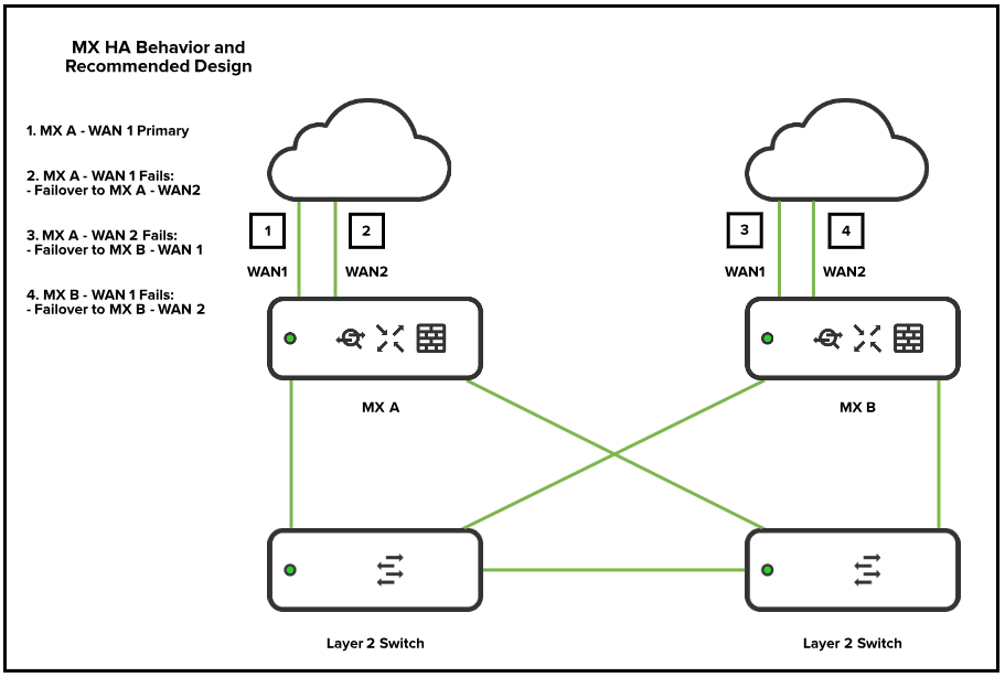
Fully Redundant (Two Switches)
In this architecture, the primary and secondary MXs are not directly connected, and VRRP heartbeats are carried between the downstream switches. This is the recommended architecture for most deployments, as there is no single point of failure in this topology.
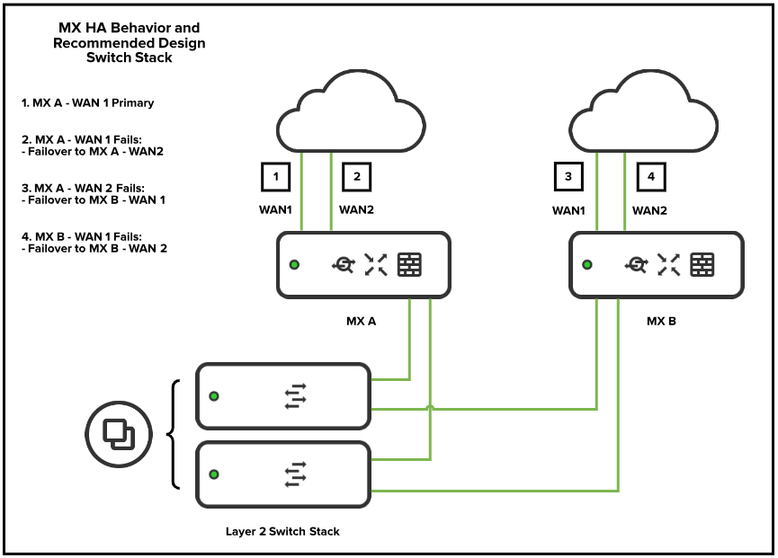
Fully Redundant (Switch Stack)
In this architecture, the primary and secondary MXs are connected via a downstream switch stack. Each switch has at least one uplink to each MX, ensuring there is no single point of failure in the topology.
High Availability with More Than Two Physical WAN Uplinks
Although only two active uplinks are supported at a time on an active/primary MX, additional uplinks should be utilized for tertiary failover on the secondary MX. One or two additional uplinks may be utilized on the secondary MX, and will become active when all uplinks on the primary MX fail or when a hardware failure occurs on the primary MX. These additional uplinks connected to the secondary MX can be part of a different IP subnet than the uplinks on the primary MX.
Troubleshooting Routed Warm Spare
If there is a problem with the routed HA configuration, there may be various symptoms that will affect the network, and it may not be obvious that the root cause is routed HA. This section outlines what issues with HA typically look like, as well as recommended troubleshooting steps.
Dual Active Issue
The most common sign of a problem with routed HA is a dual active scenario where both the primary and spare MX report in the dashboard as being active. This can be observed in the dashboard under Security & SD-WAN > Monitor > Appliance status and by comparing the current state of each appliance.
This will occur if the primary MX is online and sending heartbeats that aren't seen by the spare, resulting in the spare thinking that the primary is down. If both the primary and spare are in the active state, this will cause various issues with the network, affecting DHCP, routing, VPN, etc.
Recommended Troubleshooting Steps
If network issues appear to be related to routed HA, follow the troubleshooting steps to identify the root cause:
- Check both appliances in the dashboard (under Security & SD-WAN > Monitor > Appliance status) to check if there is a dual active scenario as outlined above.
- If both appliances are consistently reporting in the "active" state, check their LAN connection and make sure they can communicate with each other.
- If the spare MX is intermittently reporting as active while the primary remains online and active, check that both MXs can communicate with each other on all VLANs. Additionally, ensure there are no bad cables connecting the two devices or any other physical issue that could result in unreliable communication.
- Take a packet capture on the LAN side of each MX, to get a clear picture of where the VRRP heartbeats are being lost (for packet capturing guidance, refer to Packet Capture Overview article).
- If the HA pair is configured to use a virtual IP on the uplink, make sure that each pair of WAN connections (WAN 1 on each MX, for example) share the same broadcast domain so they can both be seen by the upstream device.
Firmware Upgrade Behavior
When MX appliances are configured to operate in High Availability (HA) (either in NAT/routed mode or when operating as one-armed VPN concentrators), the dashboard will automatically take steps to ensure a zero-downtime MX upgrade. This is achieved through the following automated process:
-
The primary MX downloads firmware.
-
The primary MX stops advertising VRRP.
-
The secondary MX becomes active.
-
The primary MX reboots.
-
The primary MX comes online again.
-
The primary MX starts advertising VRRP again.
-
The primary MX becomes active again.
-
The secondary MX downloads firmware* (approximately 15 minutes after the original upgrade is scheduled; the 15-minute delay for the secondary MX is a safety buffer to ensure the primary is stable).
-
The secondary MX stops advertising VRRP.
-
The secondary MX reboots and comes back online.
Note: The secondary MX will attempt to upgrade regardless of whether the primary MX upgrade was successful or not.