
Resetting Cisco Meraki Devices to Factory Defaults
Click 日本語 for Japanese
Overview
Cisco Meraki devices can be reset to factory defaults using the reset button on the device. This requires a paper clip or object with a long thin tip. Insert the tip of the paper clip into the reset button. Press and hold for 10-20 seconds, or until the power light goes out (whichever occurs first). This will reset the device to factory defaults and reboot. If a static IP address was configured for the device, it will need to be configured again using the local status page.
Resetting a Meraki appliance to factory defaults will clear the local configuration stored on that appliance. This will clear any statically assigned IP address information, Ethernet configuration, DHCP lease pool, and web proxy settings.
If a device is still in a network after being factory reset, it will re-download its previous configuration when it comes back online. This includes any previously assigned static IP addressing. If the configuration needs to be completely reset, make sure to remove the device from its network before resetting to factory defaults (you may follow the steps outlined in Adding and Removing Devices from Dashboard Networks.)
Before attempting a factory reset, it's recommended that you wait until after the status light has started cycling colors. This will ensure the device has finished booting and is prepared to accept the factory reset.
Rack-Mounted Security Appliance
To reset a rack-mounted security appliance to the factory defaults, press the button labeled Reset on the front panel of the security appliance for 10-20 seconds. This will clear the static IP address settings, DHCP lease pool, and local configuration of the device. After resetting the unit, the device will need to download its latest configuration from the dashboard. Please be patient as this could take up to 5-10 minutes.
To reconfigure a static IP address on a security appliance, please follow the instructions in Using the Cisco Meraki Device Status Page article.
Compact MX Security Appliance and Z-Series Teleworker Gateway
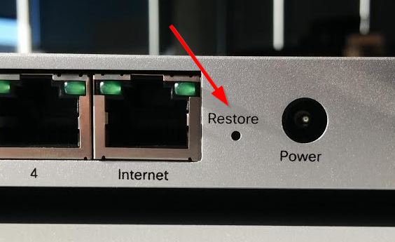
To reset a compact (non-rack-mounted) security appliance or teleworker gateway to the factory defaults, press the button labeled Reset on the back panel of the security appliance for 10-20 seconds. This will clear the static IP address settings, DHCP lease pool, and local configuration of the device. After resetting the unit, the device will need to download its latest configuration from the dashboard. Please be patient as this could take up to 5-10 minutes.
The reset button on different security appliances or Teleworker gateway appliances may have different indicators/words such as "Reset," "Restore," or simply a circular arrow icon. There is only ever one hole for a factory reset on these appliances, regardless of the label.
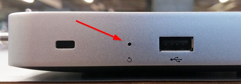
On some security appliances, the reset button is located on the side of the unit (next to the USB port) and labeled with a circular arrow:
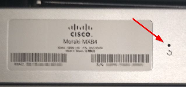
MX84
On the MX84, the reset button is located on the back of the unit, and labeled with a circular arrow:
MS Access Switches
To reset a switch to the factory defaults, press the button labeled Reset or Restore on the front panel of the switch for 10-20 seconds. Be sure to release the button after 10-20 seconds or when power light goes out (whichever occurs first). This will clear the static IP address settings and local configuration of the device. After resetting the unit, the device will need to download its latest configuration from the dashboard. This could take up to 5-10 minutes.
Note: Holding the reset button after the switch reboots will place it in factory test mode. If this has occurred, reboot the device to return it to normal behavior.
On MS420 series switches, the Restore button will be located on the right side of the switch, adjacent to the Small-Form Factor Pluggable (SFP) ports.
For diagrams indicating the location of the reset/restore button, view the MS Installation Guides articles.
For information about configuring a static IP address on the switch, view the MS Quick Start Guide.
MS350 Series Switch
On the MS350 series switches, the reset button is located on the back of the unit, labeled with a circular arrow:
.jpg?revision=1&size=bestfit&width=703&height=288)
Catalyst Series Switches (MS390, C9300/X/L)
To reset Catalyst MS390/C9K Switches:
-
While the switch is powered on
-
Hold the reset pin (for MS390) or the mode button (for C9300/X/L), then release to perform one of the following reset options
-
Additionally, C9300/X/L models feature a backup reset pin located on the rear of the switch, below and to the left of the console port.
-
| Reset option | Reset pin hold time | LED Scheme |
|
Level 1 Reset |
Reset button pressed for >=1s and <8s |
"...." |
|
Level 2 Reset |
Reset button pressed for >=8s and <20s | ".-.-" short, long alternating cycle |
|
Level 3 Reset |
Reset Button pressed for >= 20s | "----" long 3 sec on/off cycle |
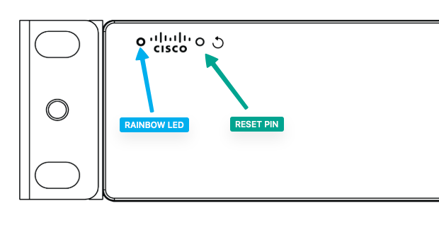
Catalyst Switch Front Panel 
MS390 Front Panel
Meraki Stage and LED Behavior
Blue beacon LED behavior
|
Off |
Pre-IOS stages |
|
Flashing / Blinking blue |
System is ready to initialize the Meraki subsystem (IOS has completely booted) |
|
Solid Blue |
Meraki subsystem is up and functional |
Meraki Stage and LED Scheme for MS390 and CAT9K
|
SN # |
Meraki Stage |
MS390
|
CAT9K |
Technical Description |
Software Naming |
|
|
|
|
Rainbow LED |
Beacon LED |
System LED |
||
|
1 |
Switch is powered off or not receiving power. |
Off |
Off |
Off |
|
|
|
2 |
Switch is powered on and is loading the bootstrap firmware. |
Solid Amber |
Solid Amber |
|
|
|
|
3 |
Switch is loading the operating system. |
Blinking Green |
Blinking Green |
|
|
|
|
4 |
System error: Switch failed to load operating system or bootstrap firmware. |
Blinking Amber |
Blinking amber |
|
|
|
|
5 |
Setting up local management and cloud-connectivity requirements. |
Cycling through different colors |
Blinking Blue |
Blinking Green |
UAC is down and trying to find an uplink |
CONNECTION_IN_PROGRESS |
|
6 |
System error: Switch failed to complete local provisioning. |
Solid Amber |
Solid Amber |
UAC is up, but the nextunnel config fetch is failing |
MERAKI_PROC_FAILURE |
|
|
7 |
Switch is completely provisioned but unable to connect to Meraki cloud. |
Solid Amber |
Solid Blue |
Solid Amber |
UAC is up, the nextunnel config fetch is done, trying to establish nextunnel or nextunnel is down |
NO_CONNECTION |
|
8 |
Firmware download / upgrade in progress |
Blinking white |
Blinking Green |
One-shot install, or install add/commit/activate operation is in progress |
UPGRADING |
|
|
9 |
There is a fault with the power supply, fan, or network module (not traffic-related) |
Alternately blinking Amber & White |
Blinking Amber |
Not currently supported; planned for a future release (not available in Aurora-MVP) |
FAN_PS_NM_FAILURE |
|
|
10 |
Switch is fully operational and connected to the Meraki cloud |
Solid White |
Solid Green |
Nextunnel is Established/Up |
CLOUD_CONNECTION_UP |
|
Stack-Jumping Recovery Process
NOTES:
Can only be done on similar switches.
- MS390s only stack with other MS390s (all models)
- C9300 and C9300X can stack with each other
- C9300L can only stack with C9300L (requires stacking kit)
- C9200L can only stack with C9200L (requires stacking kit)
Software Requirements
- Mode must be in the same mode (CLI/DNA mode or Cloud-Managed)
- Cloud-managed must be the same 'generation' of code (CS firmware or Cloud-Native IOS-XE)


STEPS
- Connect the stacking cable between the unpowered 'bad' switch and the powered 'good' switch. (STEP 1)
- Power on 'bad' switch. The 'good' switch will be the active member and overwrite the new stack member. (STEP 2)
- Wait until the stack comes online in the dashboard. Then reverse the process to unstack.
- Power off the 'bad' switch, remove the stacking cable and delete/remove the stack in dashboard.
- Power on the recovered 'bad' switch. Wait for it to fully boot/reload.
- Factory reset the switch before connecting it to an uplink.
CW Access Points
Note: This behavior is specific to CW917x Access points
Reset via the Reset button
To reset CW917x Access Points:
- Unplug AP
- Hold reset pin
- Power on AP
- Hold the reset pin to perform the below reset options.
| Reset option | Reset pin hold time | LED status |
|
0. Mode indication |
~ 5 sec |
|
|
1. Config reset |
> 10 sec | Solid white |
|
2. Full reset (maintains management mode) |
> 20 seconds | Orange |
|
3. FIPS reset (Catalyst mode only) |
> 30 seconds | Solid red |
|
4. Factory reset (back to global use AP onboarding) |
> 60 seconds | Solid pink |
|
5. Abort reset |
> 90 seconds | NA |
Note: This reset operation is consistent with traditional Catalyst-managed AP deployments and is now integrated with Meraki-managed AP deployments.
Console output is now available for reference during the reset process.

LED Indicators
MR Or Dashboard Management Mode
Your access point is equipped with a multi-color LED light on the front of the unit to convey information about system functionality and performance:
- Orange - AP is booting (permanent Orange suggests hardware issue)
- Rainbow - AP is initializing/scanning
- Blinking Blue - AP is upgrading
- Green - AP in Gateway mode with no clients
- Blue - AP in Gateway mode with clients
- Blinking Orange - AP can't find uplink
Note: Blinking Green LED indicates that the device is in site survey mode. Please see the Conducting Site Surveys with MR Access Points for more details.
Catalyst Management Mode
- Green - AP operating normally with no clients
- Blue - AP operating normally with clients
- Blinking Green - Boot loader signing verification failure
- Blinking Blue - AP is upgrading
- Blinking Green & Red - Discovery or join process in progress
- Blinking Red, off, Green, off, Blue, off - General warning; insufficient inline power
MR Access Points
Resetting the unit will clear the static IP address settings and local configuration of the device.
Outdoor Access Points
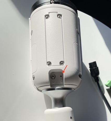
To reset an outdoor Access point (AP) to the factory defaults, press the button labeled Reset below the Ethernet port of the Access point for 10-20 seconds. After resetting the unit, the device will need to download its latest configuration from the dashboard. This could take up to 5-10 minutes.
Note: MR58 and OD2 devices do not have a reset button.
The reset button is located in a small pin-sized hole next to the Ethernet port.
![]()
To set up a static IP address on a Cisco Meraki AP, refer to the Static IP Assignment on a Cisco Meraki Access Point article.
MR70, MR78
For these models, the reset button is located next to the Ethernet port, within the cable bay.
![]()
Indoor Access Points
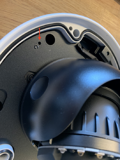
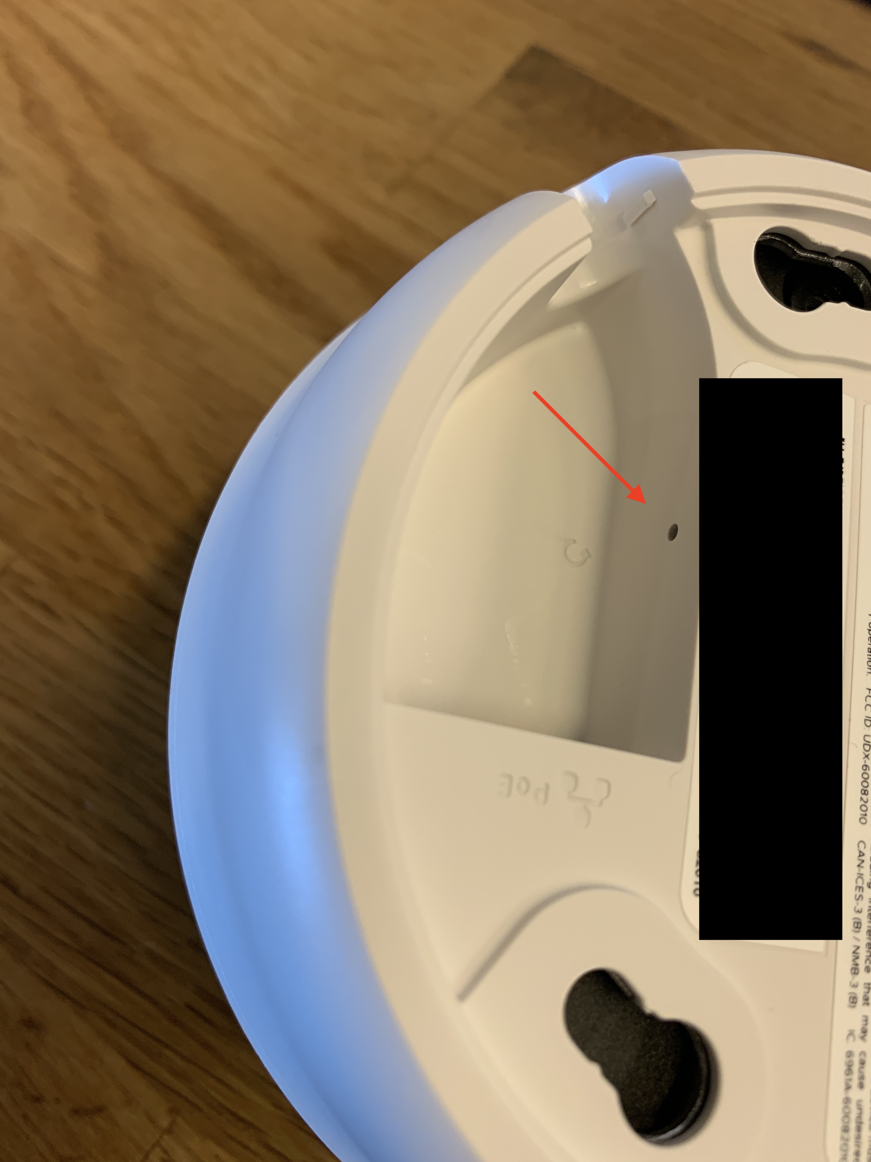
To reset an indoor access point to the factory defaults, press the button labeled Reset for 10-20 seconds. The location of this button varies and is illustrated below. After resetting the unit, the device will need to download its latest configuration from the dashboard. This could take up to 5-10 minutes.
The reset button for most indoor models is located adjacent to the power and Ethernet ports on the Access point. Exact location will vary by model.
To set up a static IP address on a Cisco Meraki Access point, visit the article for Static IP Assignment on a Cisco Meraki Access Point.
MR12, MR16, MR24, MR30H, MR36H
For these models, the reset button is located on the rear plate of the AP.
MV Security Cameras
Each camera model has a different reset button location. After resetting any camera, the device will need to download its latest configuration from the dashboard. Please be patient as this could take up to 5-10 minutes.
Stored video will not be deleted upon doing a factory reset. To delete video, the camera must be removed from the network.
- For the MV21 and the MV71, press the button located next to the Ethernet port for five seconds.
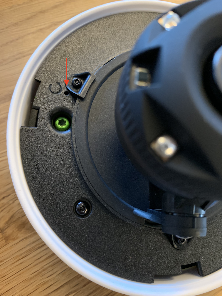
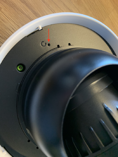
- For the MV63, the reset button is under the dome behind the desiccant packet.
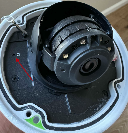
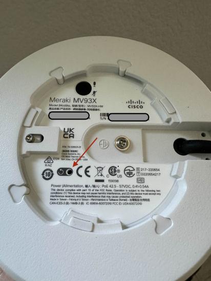
- For the MV93, the reset button is on the rear side.
- For the MV12 and MV22, turn the optical dome to unlock it from the base.
On the MV12:
On the MV22:
- For the MV52, the reset button is the under the top lens hood, towards the rear. Slide the hood of the camera away from the front lens towards the mounting plate, and slide the longer cover under the hood to find the pin hole to factory reset the camera. Note that it may require significant force to slide the plastic hood away from the camera body.
On the MV52:
- For the MV63 and MV72, you will first need to loosen four Torx head security screws before removing the optical dome.
On the MV72:
- For the MV32, the reset button is next to the Ethernet port as in the MV21 and MV71.
On the MV32:
MT Sensors
Factory Reset Button
MT10, MT11, MT12, MT14, MT20, Mt30
Next to the battery compartment, there is a pinhole button to factory reset the sensor. If the button is pressed and held for at least 5-15 seconds and then released, the sensor will reboot and it will be restored to its original factory settings by deleting all configuration information stored on the unit.
MT15, MT40
On the back of the sensor, there is a sticker with the FCC information and the serial number. A pinhole button to factory reset the sensor is located here. If the button is pressed and held for at least 5-15 seconds and then released, the sensor will reboot. It will then be restored to its original factory settings, deleting all configuration information stored on the unit.
You can also review the installation guide for the respective MT model.
MG Cellular Gateways
For instructions on factory resetting an MG Cellular Gateway, see the installation guide for the respective MG model.