
Uplink and Performance Tab
Uplink Tab
This dashboard tab facilitates the management of cellular WAN configurations and the monitoring of cellular WAN health over time. Information is organized into categories including Configuration, Status, and Live Data. The Uplink page in the Meraki Dashboard is accessible via Cellular Gateway > Cellular Gateways.
-
Configuration
This section provides information on SIM cards for the device.
The number of SIM card slots displayed on the dashboard depends on the number of SIM slots available on the device. By default, SIM 1 is the primary/active slot. Primary SIM is the one that will be activated at bootup. Active SIM, is the sim that is currently being used to establish the cellular WAN connection. On bootup, the MG will try to activate the SIM card on the primary slot.
This section displays some of the parameters involved with SIM card configuration on the MG.

-
ICCID - This is a 18-22 digit number which is derived from the SIM card
-
IMSI - This is a unique 15 digit number which is used by the network to authenticate and identify subscribers.
-
MSISDN - This is the phone number associated with the SIM card or line.
-
Status - This field displays “Active” if the sim card is actively being used to establish a cellular connection or “Not Inserted” if the sim is not inserted and “Standby” if the sim card is not the active sim.
-
Primary Configuration - This field shows if this particular sim is configured as the primary sim.
-
Access Point Name(APN)- This field displays the APN used for establishing the data session.
-
IP Type - This field shows the data connection type that would be requested from the cellular network while establishing the data session using APN. The different options are IPv4, IPv6 or IPv4v6. Ipv4 requests for an IPv4 data session only, IPv6 requests for IPv6 data session only and IPv4v6 requests for both IPv4 and IPv6, but the network can provide either or both data sessions.
-
Authentication - This field shows the authentication method for a device to establish connection to the network.
If you need to manually enter an APN, then click on the “EDIT” button to open the device configuration editor. This window will allow you to configure the below SIM settings.

-
Name - This field is to enter the APN provided by the carrier
-
IP type - The user can specify the preferred IP type for the devices connecting through that APN. The different IP types are IPv4, IPv6 and IPv4v6
Note: MG cannot currently function in a native IPv6-only environment. It is recommended that dual-stack is implemented in order to leverage IPv6 functionality and management.
-
Authentication - This field is used to specify the authentication method for the MG to establish a successful connection. The different types of authentication are PAP, CHAP and None.
-
Username - This field is used to specify the associated username
-
Password - This field is used to specify the associated password
Note : If incorrect information is entered for any or all of the parameters mentioned above, it will prevent the establishment of a data session over the cellular network, thereby causing the MG to remain offline.
Click the Update button to save changes made to the configuration.
To modify the default primary SIM slot, utilize the "MAKE PRIMARY" option, which also promptly activates the selected SIM. By default, the device is configured with SIM1 as the primary slot. However, if a SIM card is inserted into SIM slot 2 on a device with no SIM in slot 1, the device will boot up with that particular SIM in SIM slot 2.

In scenarios where two SIMs are inserted:
-
If SIM 1 is primary and active, clicking "Make primary" for SIM 2 will switch SIM 2 to primary and also activate the sim, thus making it Active.
-
If SIM 1 was active and experiences a data connection loss for over 5 minutes, a failover to SIM 2 (the secondary SIM) will occur.
For enhanced redundancy, it is advisable to utilize SIM cards from different carriers in SIM slots 1 and 2.
-
Status
This item is used to access details regarding the configuration status of a device.

-
Radio
This shows the RAT( Radio Access Technology), signal strength and band information for 4G and 5G bands. The band information shows if carrier aggregation is enabled by showing the PCC and the SCC information.
Strength is ranked using the below Indicators. More information regarding how signal strength is calculated can be found here.
Excellent - 5 Signal bars
Great - 4 Signal bars
Good - 3 Signal bars
OK - 2 Signal bars
Poor - 1 Signal bar

Click on the More signal statistics to get more details on the cellular signal quality like the RSRP and RSRQ.

-
Network
This section shows what carrier the device is actually connected to. It displays the following:

-
Provider : The Service Provider the modem is currently attached to.
-
MCC : Mobile Country Code
-
MNC : Mobile Network Code
-
Roaming Status : This indicates whether it is currently connected to a roaming network or operating within its home network coverage area.
-
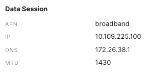
Data Session
This section shows the Access Point Name (APN) the MG51 is using to establish the data session as well as the IP, DNS, and the MTU (Maximum Transmission Unit) size which is provided by the network.
-
General

-
WAN
This shows if the WAN port is configured on the uplink. The “Configured as” field shows as “Disabled” when WWM mode is not enabled. Please refer to WWM mode document for more details on this.

-
Live Data
Uplink Traffic
This graph is used for monitoring the uplink traffic in real time

-
Historical Device Data
MG users can now take advantage of this data within the Meraki platform to quickly diagnose what’s affecting cellular connectivity, or what led to performance degradation, through historical stats— signal strength, latency, and loss—that are visual and easy to interpret
Cellular Statistics graph is used for showing signal strength such as the RSRP(Reference signal received power) and RSRQ ( Reference signal Received Quality) . You can view the data from past 2 hrs to as far as 30 days in the past.

Similarly you can also monitor the latency and loss over the primary Cellular Uplink.

Performance Tab
This dashboard tab gives a more in-depth view of the historical performance data. The Performance Tab in the Meraki Dashboard is accessible via Cellular Gateway > Cellular Gateways.
-
Radio Utilization
At a glance, this displays the active sim and the RAT that it is on. Hover over the chart to see the data and time of the active sim.

-
RSRP
This chart shows the RSRP(Reference Signal Received Power) for the device and it can be viewed by date range. Hover over the chart to see the RSRP for a particular time and date.

-
RSRQ
This chart shows the RSRQ(Reference Signal Received Quality) for the device and similar to RSRP it can be viewed by date range. Hover over the chart to see the RSRQ for a particular time and date.

For more information regarding RSRP and RSRQ, refer to the Interpreting RSRP and RSRQ section.
The next card displays the connectivity stats to a destination IP address that you would like to view the connectivity stats against.
-
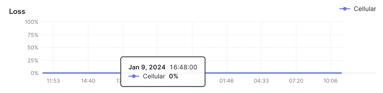
Latency/Loss
This card shows the WAN’s quality based on the network latency and loss.
The below graphs is a time series graph that helps you see the quality of the WAN link as well as the loss.

Glossary:
-
ICCID - Integrated Circuit Card Identification Number
This is a unique serial number of the sim card.
-
IMSI - International Mobile Subscriber Identity
This is a unique number that is associated with every subscriber
-
MSISDN - Mobile Station International Subscriber Directory Number
This number in a cellular network is the phone number that identifies a device during data sessions.
-
APN - Access Point Name
Its the name of the gateway between the mobile network and public Internet
-
RAT - Radio Access Technology
It is the underlying physical connection method for a radio communication network. Example of RAT’s are GSM, UMTS, LTE, 5G etc
-
PCC - Primary Component Carrier
The PCC is the main or primary carrier in a carrier aggregation setup.It typically provides the primary data connection and controls the setup of additional component carriers.
-
SCC - Secondary Component Carrier
The SCC, or secondary carrier, is an additional carrier that works in conjunction with the PCC. The SCC is aggregated with the PCC to enhance the overall data throughput and network capacity.
-
MTU - Maximum Transmission Unit
This is the size of the largest data packet that can be communicated in a single network layer transaction.
-
RSRP - Reference Signal Received Power
This is a metric that represents the received power level of the reference signals in a cellular network and it is measured in dBM
-
RSRQ - Reference Signal Received Quality
This is a metric that provides information about the quality of the received reference signals, taking into account both the signal strength and interference levels.
-
PAP - Password Authentication Protocol
PAP is a simple authentication method where the username and password are sent in plaintext to the network for verification.
-
CHAP - Challenge Handshake Authentication Protocol
CHAP is a more secure authentication method that involves a challenge-response mechanism.
-
MCC - Mobile Country Code
MCC is a unique three-digit code assigned to each country or geographical area by the International Telecommunication Union (ITU). It is used to identify the country or region where a mobile network subscriber is located.
-
MNC - Mobile Network Code
MNC is a unique two or three-digit code assigned to each mobile network operator within a country or geographical area. It is used to identify the specific mobile network to which a subscriber belongs.
Signal Strength and Signal Quality
It is recommended to not rely solely on signal bars when troubleshooting. Always check the proper signal values to get more accurate readings. Each of these values can vary for different carriers and technologies.
For transparency, the following values are how the MG cellular gateway calculates signal bars. Signal strength and quality reported will vary per modem. When deploying the MG cellular gateway, it is important to take into account the values below for a signal type to find optimal signal quality. The RSRP and RSRQ values are relevant when the modem type is in 4G/LTE or 5G.
|
Signal Bar |
4G/5G |
|
|
RSRP Range (dBm) |
RSRQ Range (dB) |
|
|
5 |
RSRP >= -83 |
RSRQ >= -7 |
|
4 |
-83 > RSRP >= -92 |
-7 > RSRQ >= -10 |
|
3 |
-92 > RSRP >= -102 |
-10 > RSRQ >= -13 |
|
2 |
-102 > RSRP >= -111 |
-13 > RSRQ >= -16 |
|
1 |
-111 > RSRP >= -140 |
-16 > RSRQ >= -20 |
Interpreting RSRP and RSRQ
RSRP (Reference Signal Received Power) and RSRQ (Reference Signal Received Quality) are influenced by various factors in a cellular network.
-
Distance from the Cell Tower:
As a mobile device moves away from the cell tower, the received signal power (RSRP) tends to decrease. The distance between the device and the cell tower is a crucial factor in signal strength.
-
Obstructions and Signal Attenuation:
Physical obstructions such as buildings, trees, and terrain can block or attenuate the radio signals, impacting both RSRP and RSRQ.
-
Antenna Gain and Configuration:
The gain and configuration of antennas at both the cell tower and the mobile device play a role in signal reception.
-
Network Load and Congestion:
High network load and congestion can affect the quality of the received signals. RSRQ takes into account interference and congestion levels, providing a more comprehensive quality metric.
-
Weather Conditions:
Weather conditions such as rain, snow, or atmospheric disturbances can attenuate or scatter radio signals, affecting both RSRP and RSRQ.
-
Interference:
Interference from other electronic devices, adjacent cells, or co-channel interference can affect the quality of the received signals and, consequently, RSRQ.
-
Transmission Power of the Cell Tower:
The power at which the cell tower transmits signals can influence RSRP. Higher transmission power generally results in stronger RSRP values.
Keep in mind that these values will vary as conditions change. The above measurements do not give us a definitive answer of what constitutes a successful connection.