
Templates for Switching Best Practices
As a network deployment grows to span multiple sites, managing individual devices can become highly cumbersome and unnecessary. To help alleviate these operating costs, the Meraki MS switch offers the use of templates to quickly roll out new site deployments and make changes in bulk.
This guide will outline how to create and use MS switch templates in Dashboard.
Planning a Template Deployment
Before rolling out a template deployment (or enabling templates on a production network), it may be helpful to plan the "units" that make up your deployments. This involves asking questions such as:
- What are my sites? (e.g. retail location, school, branch office, etc.)
- How many switches are at each site?
- Are multiple switches at the same site configured the same way? (e.g. access switches, classroom switches, etc.)
The answers to these questions should directly affect your template deployment, specifically your use of template networks and switch templates.
Layer 3 Routing & DHCP
Layer 3 settings for networks bound to a template act as exceptions to the template. The Routing & DHCP, OSPF routing, and DHCP servers & ARP pages will be configurable on each network bound to a template and behave the same as if the network was not bound to a template. The one difference is that setting email alerts for newly detected DHCP servers on the DHCP servers & ARP page is available from the parent template's Network-wide > Configure > Alerts page and therefore applies to all networks bound to the template.
Template Networks
A "site" in network deployment terms is usually the same as a "network" in Dashboard terms; each site gets their own Dashboard network. As such, when planning multiple sites to be configured the same way, they will share a template network.
A template network is a network configuration that is shared by multiple sites/networks. Individual site networks can be bound to a template network, so changes to the template will trickle down to all bound sites. A new network can also be created based on a template, making it easy to spin up new sites of the same type.
When planning a template deployment, you should have one template network for each type of site.
Switch Templates
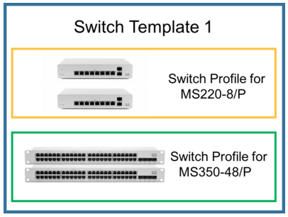
If multiple switches on a site share the same port configuration, they can easily be deployed and updated using switch templates. Within a template network, a switch template defines the per-port configuration for a group of switches. For example, if all sites contain multiple MS220-24 switches that are all configured identically, an administrator can set up a switch template for their MS220-24 switches. This way, whenever a new MS220-24 is installed at a site, it will automatically assume its switch template and configure its ports accordingly.
When planning a template deployment, if multiple switches share the same configuration, consider using a switch template for each type of switch.
Templates can be overwritten by a local port configuration. If the port of a template-bound switch is manually configured, that manual configuration will be "sticky" and remain on the switch, even if the template is changed.
Different MS switch models cannot share the same template.
Guidelines and Limitations
1. STP bridge priority cannot be changed on switch stacks using templates. In a network template, switch templates can be assigned STP bridge priority values from Switching > Configure > Switch settings > STP configuration. A value assigned to a switch template, however, will only propagate to the standalone switches bound to that template; switch stacks will retain the default STP priority of 32768.
If an MS switch stack must be the root bridge of an STP domain that has at least one other MS switch stack, it should be placed in a Dashboard network that is not bound to a network template for the STP priority value configured on it to take effect.
The following diagram shows the relationship between network templates and switch templates:
Configuration
The following sections walk through configuration and use of switch templates in dashboard:
Creating a Template Network
As outlined above, a template network should be created for each type of site to be deployed.
To create a template network:
- In dashboard, navigate to Organization > Monitor > Configuration templates.
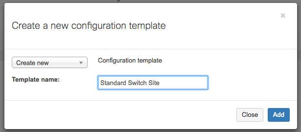
- Click Create a new template.
- Select a descriptive name for your template. If this is a completely new template, select Create new and Switch template.
- If this template should be based on an existing network, select Copy settings from and an existing switch network.
- Click Add:
- If you would like to bind existing networks to this new template, select those networks as Target networks and click Bind. Otherwise, click Close.
- Make sure you click on the "Save changes" button at the bottom of the page.
Multiple device types can be managed within a single template, acting as a combined network. For more information on managing non-switch devices in a template, refer to our documentation.
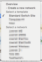
Once a network has been bound to this template, the template network should appear in the Network drop-down:
Configuring a Template Network
Once a template has been created, it can be configured with some global switch settings. These settings will also apply to all networks bound to this template.
To configure a template network, select the template from the network drop-down and configure settings normally under the Switching > Configure menu options. This can include setting a global management VLAN, IPv4 ACLs, port schedules, etc. Switch templates can also be configured here, as detailed below.
Please note that any configuration changes made here will apply to all bound networks.
Creating and Using Switch Templates
Switch templates can be used to bulk configure switches of the same model.
To create a switch template:
- Select the appropriate network template from the network drop-down.
- Navigate to Switching > Configure > Switch templates.
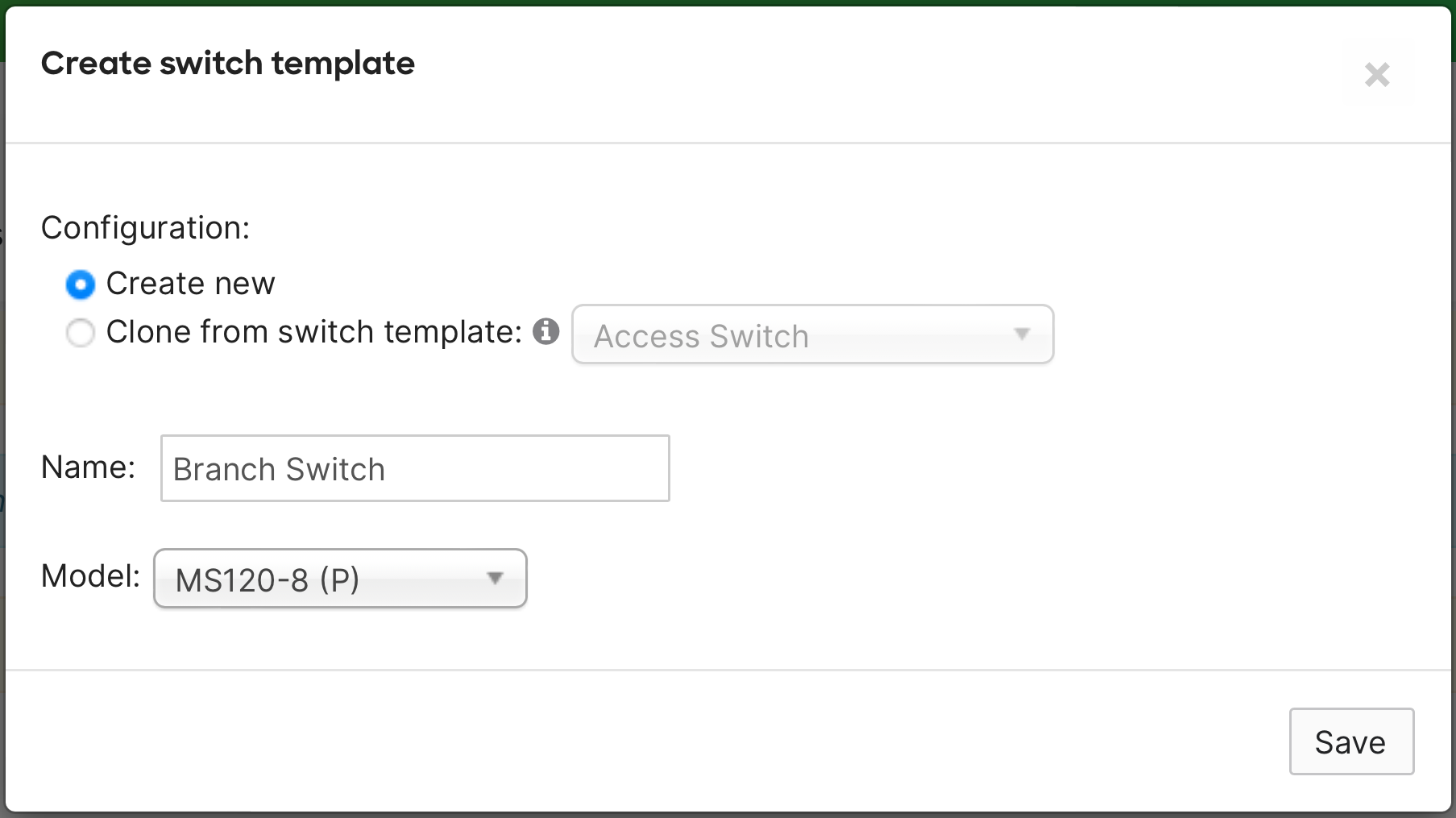
- If no templates have been created, a Create switch template window will appear. Otherwise, click Create switch template.
- Select a descriptive name and the switch model to be configured.
- Click Save:
- Click on the newly created template.
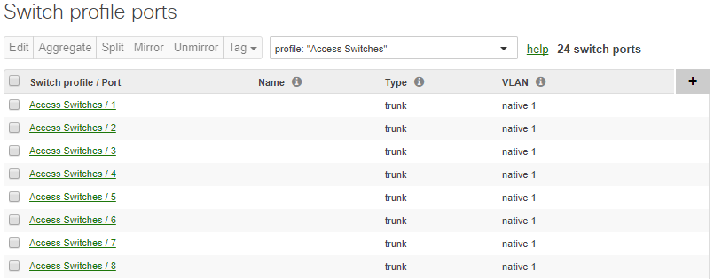
- To configure the template, select View ports on this switch template.
- The following port configuration page can be used identically to the normal switch port configuration page:
- Navigate back to the switch template under Switching > Configure > Switch templates > Template name.
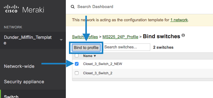
- Click Bind switches.
- Select one or more switches, then click Bind to profile:
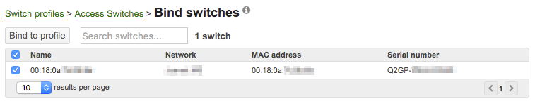
All bound switches will now use the port configuration set in the switch templates. Any changes made in the template will now affect all bound switches.
Local Overrides
Once a switch has been bound to a template, it can still be configured normally through Dashboard. Any port configuration changes made directly on the switch will override the template configuration, and be reported as a local override. If there is a need to override template configuration on a large scale, it is recommended to keep the switch port count (with local overrides) per network up to 2500. For better performance on loading the switchport page, reduce the count to 2000.
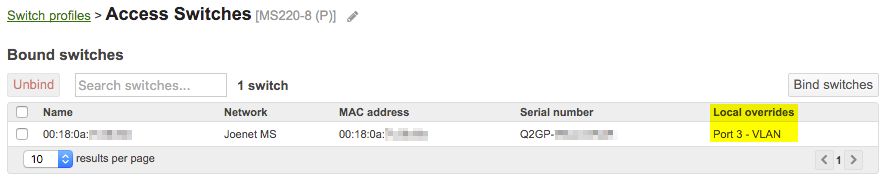
In the example below, the bound switch was directly configured to have a custom VLAN set on port 3. In the template network, under Switching > Configure > Switch templates, this configuration change is shown under the Local overrides column:
Auto-Binding Switches
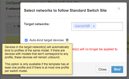
When a new network is bound to an existing template with at least one switch template, the option is available to "auto-bind" switches to that template's templates. This dramatically reduces the amount of work necessary to set up a new site; if templates exist for every switch model to be deployed, the only necessary configuration is binding the network to the template.
To auto-bind switches in a new network:
- Create a new switch network.
- Add devices to the network as normal.
- Navigate to Organization > Configuration templates > Template name.
- Click Bind additional networks.
- Select the newly created network, and check Auto-bind target devices.
- Click Bind:
All switches in the new network will now automatically be bound to their appropriate templates.
Auditing a Template Deployment
Though templates can be used to consolidate most switch configuration, there may be exceptions for individual ports or settings that necessitate local configuration changes on the switch. Since local configuration changes override template and template configurations, it is important to keep track of any local configuration changes across the organization.
To view local configuration overrides of a template:
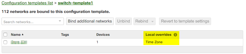
- Navigate to Organization > Configuration templates > Template name.
- The Local overrides column will show if any networks are overriding the template configuration:
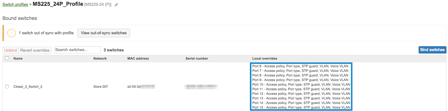
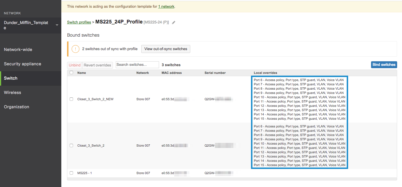
To view local configuration overrides of a switch template:
- Select the appropriate template from the network drop-down.
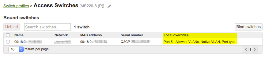
- Navigate to Switching > Configure > Switch templates > Template name.
- The Local overrides column will show if any switches are overriding the template configuration:
Managing Scheduled Firmware Upgrades in Template Deployments
Firmware Updates are scheduled for a Parent template network but occur at the individual network level. The time zone used for these updates is determined by the Local time zone setting found under Network-wide > Configure > General for each specific network.
When a new network is created and bound to a template, or when an existing network is bound to a template, its Local time zone setting will initially inherit the value configured in the parent template network.
Therefore, if your template deployment includes switches across multiple time zones and you wish to perform Scheduled Firmware Updates in the local time zone of each site, you must explicitly configure the Local time zone for each individual bound network. This ensures that each network has its correct local time zone, independent of the template, allowing for precise local scheduling of firmware updates. To achieve this, your deployment should be structured such that switches belonging to different time zones are located in separate networks (e.g., a unique network per site location, or a unique network per region assuming the devices in that region are all in the same time zone).
To configure the local time zone for a specific network:
- Select the appropriate network (the individual site or region network, not the parent template network) from the network drop-down menu in Dashboard.
- Navigate to Network-wide > Configure > General.
- Under Local time zone, select the correct Time Zone for the devices in the selected network:

- Click Save Changes.
Switch Replacement Walkthrough for Stacks
Below are instructions for how to copy configurations from a failed switch that is part of a stack and where the network is bound to a template.
-
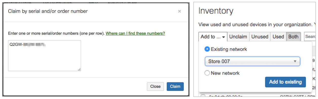
On the Organization > Configure > Inventory page, claim the new switch and then add the new switch to the existing network.
- Bind new switch to the switch template.
-
Navigate to the parent template in dashboard.
-
Navigate to Switching > Configure > Switch templates within that template.
-
Click on the corresponding template.
-
Click the Bind switches button.
-
Click the checkbox next to the new switch and click the Bind to switch template button.
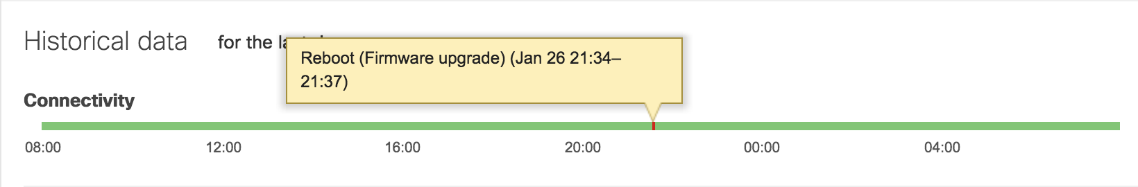
- Firmware upgrade for the new switch.
-
Provide the new switch a physical uplink connection and then power it on. The new switch needs to be brought online as a standalone device, not yet added to the stack so that it can update its firmware.
-
Confirm via the connectivity graph or Support that the switch has upgraded its firmware.
-
While the new switch upgrades, you may proceed with the below steps, stopping before Step 8 until the new switch has had a chance to upgrade.
- Obtain Current Configuration.
-
Navigate to Switching > Configure > Switch templates within the parent template.
-
Click on the template in question.
-
Filter in the Search switches… field for the name of the old switch.
-
Note the local override configuration. Save in a text editor for use in Step 5.
-
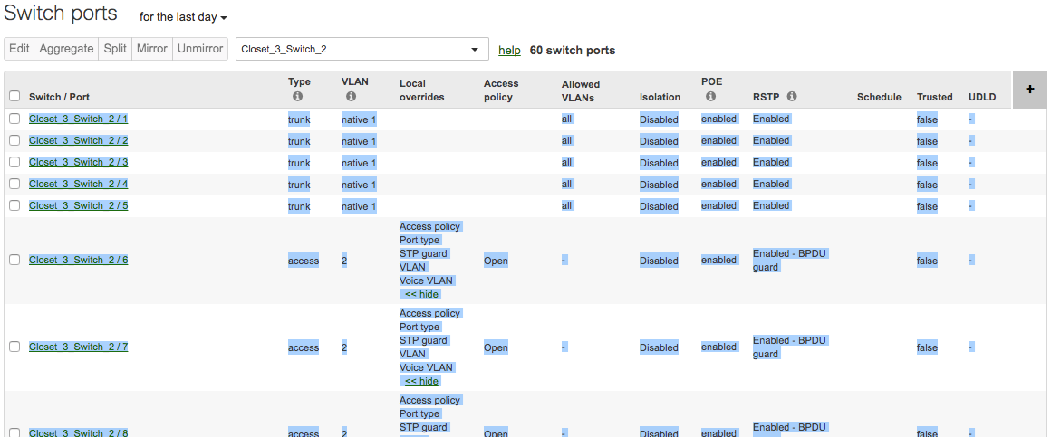
In the child network, navigate to the Switching > Monitor > Switch ports page.
-
In the Search switches… field, filter by the name of the old switch and select the below column options.
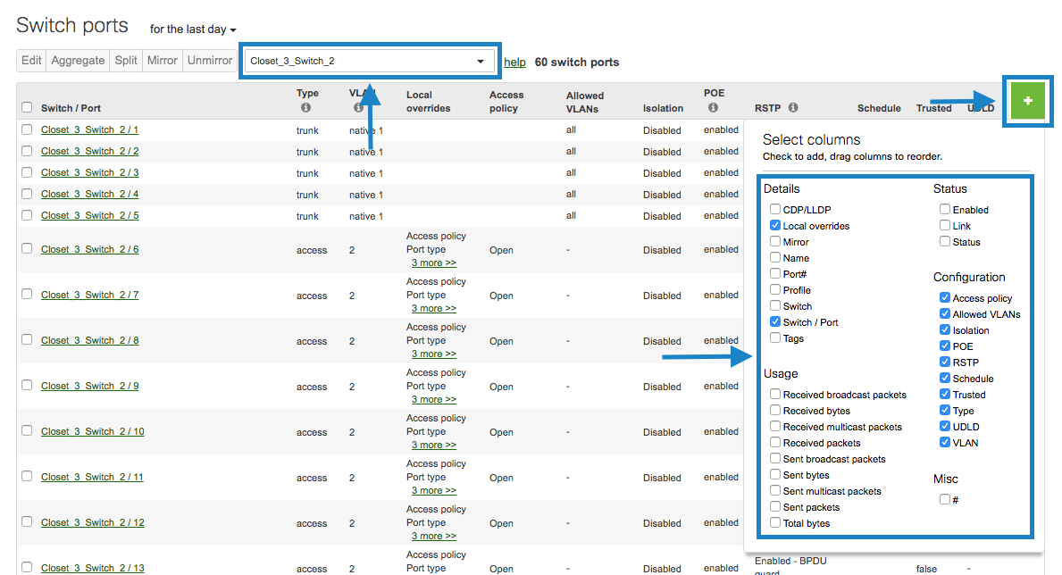
- Then, take screenshots of the port configurations or copy and paste into a spreadsheet or text editor application.
- Configure replacement switch.
-
On the Switching > Monitor > Switch ports page of the child network, configure the switch ports of the new switch based on the configuration gathered in Step 4.
-
Once complete, navigate back to the switch template details page from Step 4 and ensure that the local overrides between the old and new switch match.
- Power down the old switch.
- Unbind Old Switch from template.
- On the switch template details page, click the check box next to the old switch and then click the Unbind button.

- Add the new switch to the stack.
-
After confirming that the new switch has upgraded its firmware as mentioned in Step 3, power down the new switch.
-
In the child network, navigate to the Switching > Monitor > Switch stacks page.
-
Click on the stack in question.
-
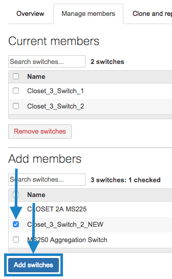
Click the Manage members tab.
-
Under Add members, click the checkbox next to the new switch and then click the Add switches button.
- Remove the old switch from the stack.
-
In the child network, navigate to the Switching > Monitor > Switch stacks page.
-
Click on the stack in question.
-
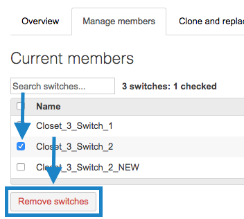
Click the Manage members tab.
-
Click the checkbox next to the old switch and then click the Remove switches button.
- Physically cable and stack the new switch.
- Power on the new switch.
Additional Notes and Resources
If many networks are being deployed at once, the bulk network creation tool can be used to bind templates in bulk.
Please reference our documentation for more information on Meraki configuration templates.