Switch Ports
Learn more with these free online training courses on the Meraki Learning Hub:
Making Configuration Changes
On the Switching > Monitor > Switch Ports page, administrators can name ports, turn ports on/off, enable spanning tree (RSTP), define port types (access/trunk), and specify VLANs (data and voice). It is recommended to keep the total switch port count in a network to fewer than 8000 ports for reliable loading of the switch port page.
Switchport page may have issues loading if a dashboard network exceeds 400 switches per network.
Editing a port(s)
In order to make changes to a port or port group on an MS switch:
- Select the port or ports to be configured by checking their perspective check box(es).
- Choose Edit and make the desired changes. See the "Port configuration" section for all configurable items.
- Once the changes have been made, save them by selecting Update. This will instantly push the changes to the MS switches in the network.
Port configuration
The following fields are configurable on each switch port.
- Name: Description of the port.
- Tags: Labels that can be used to identify this port or a group of ports.
- Port status: Enable/Disable the port.
- Stacking: Enable flexible stacking on this port.
- RSTP: Rapid Spanning Tree Protocol (RSTP) and STP guards can be configured at the port level. For more information on port level spanning tree configuration, check out our article on Configuring Spanning Tree on Meraki Switches.
- PoE: Available on PoE switches only. Enable/Disable Power over Ethernet on this port.
- Link negotiation: Select the desired link speed.
Half Duplex is not supported on MS350 and MS355 series switches.
- Port Schedule: Apply a port schedule policy. Learn how to use port scheduling here.
- Port Isolation: Enabling this feature prevents any isolated port from communicating with other isolated ports.
- Trusted DAI: Enable/Disable the trusted status for Dynamic ARP Inspection.
- UDLD: Alert/Enforce Unidirectional Link Detection on the port.
- Type: Switch ports can be configured as one of two types:
- Trunk: Configuring a trunk port will allow the selected port to accept/pass 802.1Q tagged traffic. This type is usually used for connections to other switches or access points.
- Access Policy: Apply a restriction policy to this port
- Native VLAN: The switch will send traffic for this VLAN as untagged. (Note: MS390s/C9000s will use VLAN 1 as default if no native VLAN is specified).
- Allowed VLANs: Only these VLANs will be able to traverse this link.
-
PortFast Trunk: Allows a trunk port to more quickly transition to the STP Forwarding state.
Note: This feature is supported starting in IOS XE 26.1.1. To utilize portfast trunk, please upgrade to IOS XE 26.1.1 or any later release.
-
Before enabling this feature, make sure that there are no loops in the network between the trunk port and the connected end-device as it may lead to network instability.
-
Enabling this feature allows the IOS XE portfast trunk to be enabled on trunk ports, applying the spanning-tree portfast trunk option to the port(s) in question.
-
- Trunk: Configuring a trunk port will allow the selected port to accept/pass 802.1Q tagged traffic. This type is usually used for connections to other switches or access points.
- Access: Configuring an access port will place all traffic on its defined VLAN and will only pass untagged traffic. This type is usually used for connections to end-users.
- Access Policy: Apply a restriction policy to this port.
- Open: All devices will be able to access this port.
- MAC allow list: MAC allow list allows users to enter up to 20 MAC addresses they want to be permitted to pass traffic on a particular interface, restricting traffic on that interface to the configured MAC addresses only. MAC addresses may be entered in aa:bb:cc:dd:ee:ff format or aaaa.bbbb.cccc format. (NOTE: Starting with MS18 MS classic switches will allow you to set a maximum number of MAC addresses allowed in the Allow MAC list. This is NON-sticky, for sticky please use the sticky MAC allow list option. )
Configuration:
-
Navigate to Switching > Monitor > Switches and select your switch. In the mimic panel, select the port to configure and then click the pencil icon in the Configuration section.
- Navigate to the Access Policy drop-down field and Select MAC allow List
-
Enter up to 20 MAC addresses to allow on the interface and click Update
-
- Access Policy: Apply a restriction policy to this port.

- Sticky MAC allow list:
Like MAC allow list, Sticky MAC allow list also allows users to configure between 1-20 MAC addresses allowed to pass traffic on a particular switch port, but Sticky MAC also allows MAC addresses to be dynamically learned on an interface. Users can either program the allowed MAC addresses statically into the Allowed listed MACs list, or allow for the switchport to dynamically learn the MACs. For example if you set the number of Sticky MACs to 5 and program 1 in the allow list, the next 4 MACs dynamically learned will be programmed into the stick MAC list. Any MACs learned after this will be denied access to that specific port.
Configuration:
-
Navigate to Switching > Monitor > Switches and select your switch. In the mimic panel, Select the port to configure and then click the pencil icon in the Configuration section.
-
Navigate to the Access Policy drop-down field and Select Sticky MAC allow List
-
Enter a maximum number (between 1-20) of Sticky MACs to allow on the interface
-
(Optional) Enter any static sticky MACs to allow on the interface in the Allow Listed MACs
-
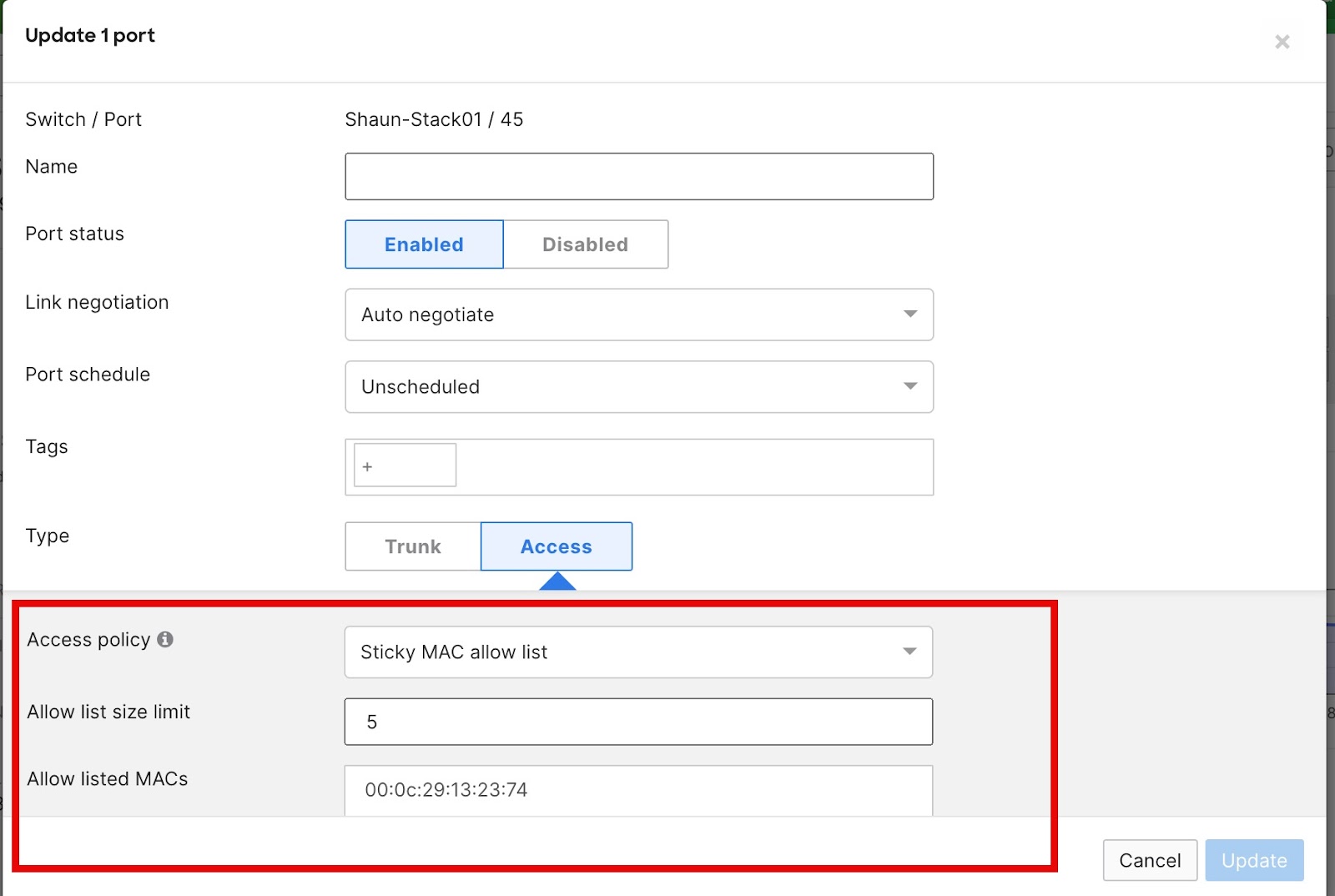
In this example the number of sticky MACs is set to 5 with one sticky MAC being hard coded. The switch will now learn the next 4 MACs that are seen on this switchport dynamically to make the total of 5 Sticky MACs. It can take up to 5 minutes for the learned MAC to appear in the dashboard.
Sticky MAC addresses persist through a device reboot.
- User-defined access policy: Administrators may define a policy for authentication via 802.1x or MAB. Learn more about access policies here.
- VLAN: All traffic will be placed on this VLAN.
- Voice VLAN: CDP/LLDP capable voice devices will be able to use this VLAN.
The option for MAC allow list and Sticky MAC allow list on MS390 and C9300-M switches requires CS 16+ firmware version. If the switches are running prior firmware versions (MS 15.5 and/or CS 15.5 or older), please contact Meraki Support in order to enable this feature set.
Note: In Catalyst IOS-XE you won't be able to configure the same MAC address in two different interfaces.
- Energy Efficient Ethernet (EEE): Enable/disable Energy Efficient Ethernet (EEE)
Searching for ports
The virtual stack allows an administrator to view all switch ports in one easy-to-navigate page. To further simplify switch port management, a dynamic search bar is available at the top to allow for quick searching of ports.
Search terms
- Enter any value in to the search omnibox for an instant search result
- Use conditional operators to separate multiple search queries (AND, OR)
- Use a wildcard to search for more general results ( * )
- Use a dash to exclude a search value ( - )
- Enter specific search terms to find a particular port:
Meraki is committed to providing an inclusive experience for our customers. The following section contains language that does not adhere to our standards for inclusivity. We are working with our partners/teams to replace it.
|
Search Type
|
Search Value
|
Result
|
Example |
|---|---|---|---|
|
Port |
port:value |
return all specified ports or port ranges |
port:1-10 |
|
Module (MS390 & C9300-M) |
module:value
|
return or exclude (using -) module model types
|
module:8x10 (only 8x10 modules) -module:8x10 (all except 8x10 modules) -module:0 (excludes all modules models) |
|
Name |
name:value |
return all ports with the specified switch name |
name:"joe's desktop" |
| Switch | switch:value | return all ports for the designated switch(es) | switch:"1st floor" |
|
Detected Uplink
|
is:uplink
|
return interface(s) detected as uplink to Meraki Cloud
|
is:uplink not:uplink |
|
Tags |
tag:value |
return all ports with the specified tag |
tag:"blue 132" |
|
VLAN |
vlan:value vlan:native vlan:voice |
return all ports with the specified vlan return all ports with a native vlan return all ports with a voice vlan |
vlan:"60" vlan:"native 60" vlan:"voice 20" |
| LLDP | lldp:value | return all ports containing matching LLDP information | lldp:"MR24" |
|
Type |
is:value |
will return all ports with type "trunk" or type "access" |
is:trunk |
|
Link |
link:value |
return all ports with the link type set to specified speed/duplex |
link:"100 mbps" link:"10 gbps" |
| Link Aggregate | is:aggregated | return only link aggregated (LACP) ports | is:"aggregated" |
| Access Policy | ap:value | return all ports with the specified access policy applied (wildcard supported) | ap:* |
| Port Schedule | schedule:value | return all ports with the specified port schedule (wildcard supported) | schedule:* |
|
Group
|
group:value
|
return all ports belonging to a common group (the virtual stack automatically categorizes the 3 most common configuration types into groups 1,2 and 3) |
group:1 group:2 group:3 |
|
MAC Allow list
|
mac_whitelist:*
|
return all ports with a mac-allowlist enabled (you can substitute the * with a mac address value using colons as separators) |
mac_whitelist:aa:bb:cc:dd:ee:ff mac_whitelist:* |
The search tool is also capable of intelligently combining multiple search queries. See a few examples below.
Search: name:"joe's port" AND switch:"2nd floor POE"
Result: returns all port(s) with the name "joe's port" on the switch named "2nd floor POE"
Search: port:1-15 link:"10 gbps" switch:"2nd floor IDF"
Result: Returns all ports configured for 10gbit from the port range of 1-15 on the switch named "2nd floor IDF"
Link Aggregation
The MS switches support Link Aggregation (LACP) groups of up to 8 ports on the same switch or physical stack. A "Link Aggregate" is a combination of ports that act as one logical link. This is often referred to as Link Bonding, Link Aggregation, or EtherChannel. A link aggregate will load balance across the different physical links for additional performance, and will also give higher reliability because the link aggregate will continue to function as long as at least one of the physical links is working.
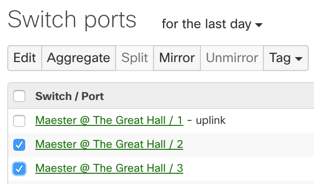
To configure an aggregate, simply choose the ports to be aggregated by checking their respective boxes (under Switching > Monitor > Switch Ports page) and then select the Aggregate option at the top of the page.

By default, link-aggregation groups are configured to run in LACP active mode.
Switches on MS firmware use an adaptive LACP active implementation, in which, the link-aggregation group is not completely suspended if the LACPDUs from the connected device are not received on the links. Instead, the switch allows one link in the aggregation to retain connectivity, to ensure that mis-configurations do not lead to either of the connected devices becoming isolated.
If you are setting up a link-aggregation with a device that does not support LACP, you can disable the Enforce LACP active option from the port configuration UI.
Please note: This is NOT a supported configuration. For LAG to work properly, both devices should be configured to use LACP negotiation.

The option for controlling LACP enforcement mode is currently available on MS firmware only. To enable the UI for this feature on your Dashboard Organization, please reach out to Meraki Support.
When LACP active enforcement is disabled, the ports will continue to send out LACPDUs, to support compatibility with LACP passive. However, the links in the aggregation will not be suspended if LACPDUs are not received on the links.
MS390 and C9300 switches use a strict LACP active implementation. If the connected device is not configured for LACP, the link-aggregation is suspended as a whole. The LACP active configuration cannot be disabled on these switches.
Note: Disabling LACP enforcement can lead to link-state and traffic-forwarding inconsistencies, and is not recommended.
Note: It is generally recommended that ports are first aggregated and then physically connect the aggregated ports. Be sure to configure the aggregate (or have LACP enabled) on both ends of the link. Configure the downlink device first, wait for the config to state up to date, before configuring the aggregation (uplink) device. If the process is performed in the uplink side first, there may be an outage depending on the models of switches used. For c9300-M/MS390s, the process described must be followed to ensure the aggregation forms correctly.
Make sure both switch ports share the same configuration, including tags, prior to aggregating.
c9300-M / MS390 are limited to 128 LACP groups per standalone switch or switch stack (a stack of 8 switches is still limited to 128 LACP groups). There is no limit to the number of LACP groups on other platforms, provided there are enough member ports available in the switch or stack.
For example, in order to create 8 LACP groups, each including the maximum of 8 ports per group, the switch stack must have at least 64 ports.
Note: (applicable to any non c9300-M/MS390s) By default, prior to configuring LACP, the MS series runs an LACP Passive instance per port. This is to prevent loops when a bonded link is connected to a switch running the default configuration. Once LACP is configured, the MS will run an Active LACP instance with a 30-second update interval and will always send LACP frames along the configured links.
Note: For additional information on Link Aggregation and Load Balancing, please refer to this article.
Note: When configuring LACP between Meraki MS and Catalyst, it may be advantageous on the Catalyst switch to disable the feature "spanning-tree etherchannel guard misconfig" if there are issues with getting the LACP aggregate established.
Selecting Aggregate ports
In the virtual stack, select the ports to be aggregated. Once the ports have been selected, choose Aggregate at the top or bottom of the port list and accept the change notification.
Note: Link Aggregation is supported on ports sharing similar characteristics such as link speed and media-type (SFP/Copper).
Splitting Aggregated ports
To split an aggregated link, simply select the aggregated port and choose Split. This will revert the changes and split the group into its own separate ports.
*For more specific configuration and interoperability information, please reference our documentation.
Port Mirroring
It may be necessary to configure a mirrored port or range of ports. This is often useful for network devices that require monitoring of network traffic, such as a VoIP recording solution or an IDS (Intrusion Detection System).
MS switches support one-to-one or many-to-one mirror sessions. Intra-stack port mirroring is available on our stackable switches. Only one active destination port can be configured per switch/stack.
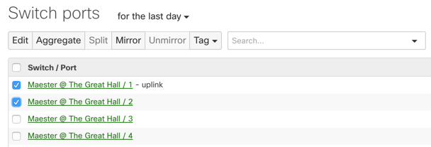
In order to enable and configure a mirrored port or range of ports, navigate to Switching > Monitor > Switch Ports. On this page select the ports that are intended for mirroring and hit the Mirror button:
Next, enter the destination port for the mirror session. If the ports are in a switch stack then also select the desired switch in the stack for the mirror destination.
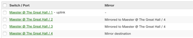
Once the Mirror is configured it can be easily identified using the Mirror column in Dashboard: