
MS355 Series Installation Guide
About this Guide
This guide provides instruction on how to install and configure your MS355 series switch. This guide also provides mounting instructions and limited troubleshooting procedures. For more switch installation guides, refer to the switch installation guides section on our documentation website.
Product Overview
Physical Specifications
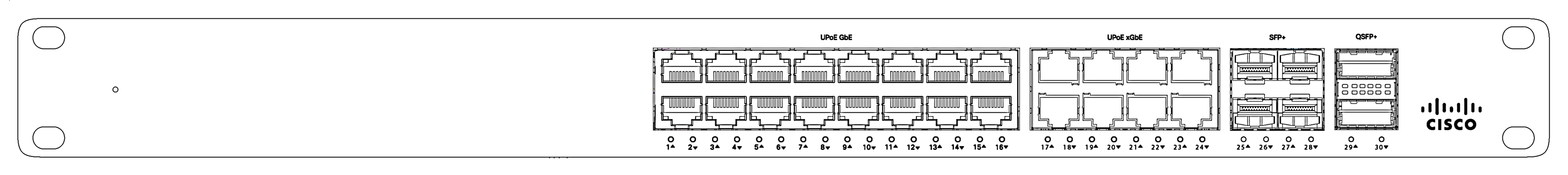
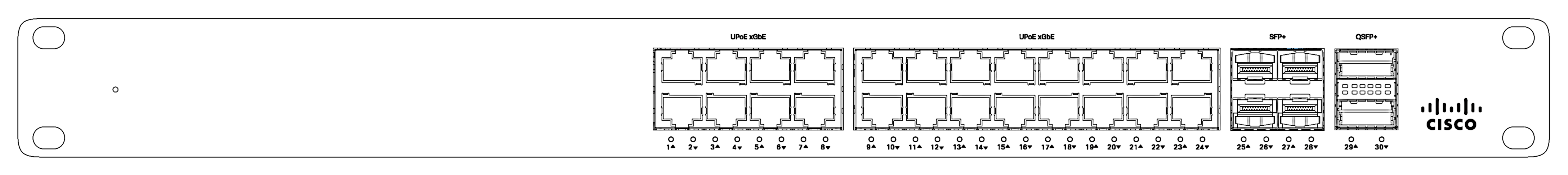
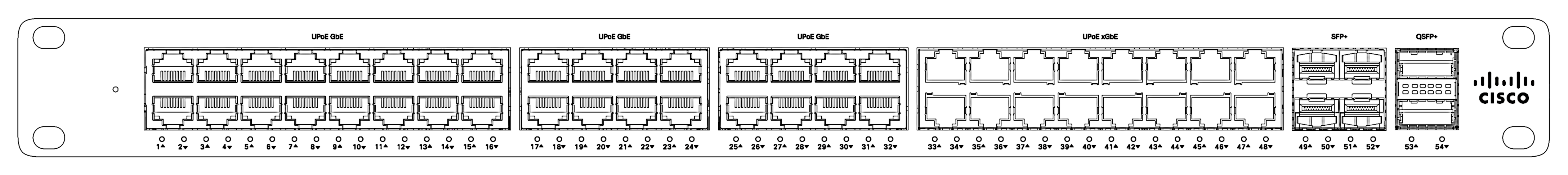
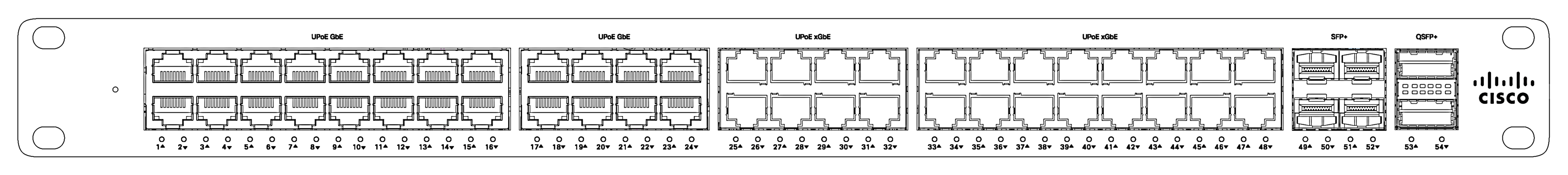
| MS355-24X | MS355-24X2 | MS355-48X | MS355-48X2 | |
| 1Gbe RJ45 | 16 |
- |
32 | 24 |
| mGbe RJ45 | 8 | 24 | 16 | 24 |
| 10Gbe SFP+ | 4 | 4 | 4 | 4 |
| 40Gbe QSFP+ | 2 | 2 | 2 | 2 |
| 100G Hardware Stack Port | 2 | 2 | 2 | 2 |
| Dedicated Mgmt Interface | 1 | 1 | 1 | 1 |
| UPoE Capable | Yes, 740W | Yes, 740W | Yes, 740W | Yes, 740W |
| Hot Swap Power Supply | Yes, Dual | Yes, Dual | Yes, Dual | Yes, Dual |
| Hot Swap Fans | Yes, 3x | Yes, 3x | Yes, 3x | Yes, 3x |
| Power Input |
100 - 240 VAC, 47-63 Hz |
100 - 240 VAC, 47-63 Hz |
100 - 240 VAC, 47-63 Hz | 100 - 240 VAC, 47-63 Hz |
|
Power Consumption |
110 - 1793W | 110 - 1793W | 110 - 1793W | 110 - 1793W |
| Operating Temperature | 32°F - 113 °F 0°C - 45°C |
32°F - 113 °F 0°C - 45°C |
32°F - 113 °F 0°C - 45°C |
32°F - 113 °F 0°C - 45°C |
| Storage and Transportation Temperature |
-4°F - 158°F -20°C - 70°C |
-4°F - 158°F -20°C - 70°C |
-4°F - 158°F -20°C - 70°C |
-4°F - 158°F -20°C - 70°C |
| Humidity | 5% to 95% | 5% to 95% | 5% to 95% | 5% to 95% |
| Mounting | 1U Rack Mount | 1U Rack Mount | 1U Rack Mount | 1U Rack Mount |
Product View and Physical Features
Front Panel
MS355-24X Series Front Panel
MS355-24X2 Series Front Panel
MS355-48X Series Front Panel
MS355-48X2 Series Front Panel
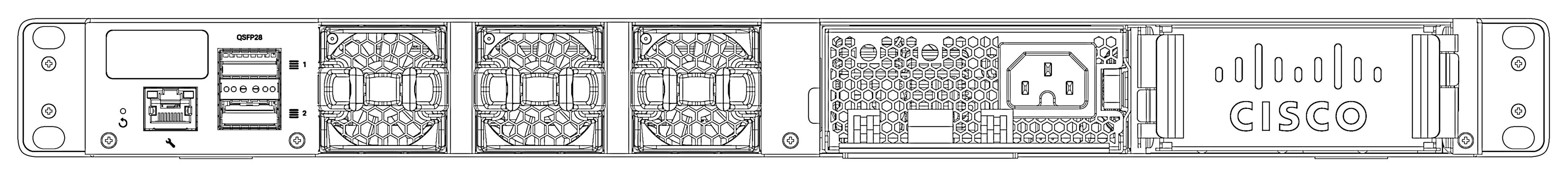
Back Panel
MS355 Series Back Panel
Ports and Status Indicators
The MS uses LEDs to inform the user of the device's status. When the device powers on, all the Internet LEDs flash twice. Additional functions are described below, from left to right.
Front Panel Components
|
Item |
Function |
LED Status |
Meaning |
|---|---|---|---|
|
1 |
Power |
Solid orange |
Switch is unable to connect to the Meraki cloud |
|
Flashing white |
Firmware upgrade in process |
||
|
Solid white |
Switch is fully operational and connected to the Meraki cloud |
||
|
Off |
Switch does not have power |
||
|
2 |
Switch Ports |
Off |
No client connected |
|
1GbE RJ45 |
Solid Green |
1 Gbps |
|
| Solid Orange | 10/100 Mbps | ||
|
mGbE RJ45 |
Solid green |
10 Gbps |
|
| Solid Orange | 1/2.5/5 Gbps | ||
| SFP+ | Solid Green | 10 Gbps | |
| Solid Orange | 1 Gbps |
Additionally, there is a RESTORE button available on the back panel.
Insert a paperclip if a restore is required.
-
A brief, momentary press: To delete a downloaded configuration and reboot.
-
Press and hold for more than 10 sec: To force the unit into a full factory restore.
Back Panel Components
|
Item |
Function |
LED Status |
Meaning |
|---|---|---|---|
|
1 |
Restore |
N/A |
Restore button to clear switch IP and local configuration settings |
|
2 |
Management Interface |
Green |
Connected, used for easy access to the local status page |
|
3 |
Stack Ports |
N/A |
Stack Cables are connected here |
|
4 |
Redundant Fans |
Green |
Active and operational |
|
5 |
Redundant Power Supplies |
Green |
Active and functional power supplies |
Power cords may be ordered separately.
Equipment is to be used only in a restricted access location and installed/operated only by trained service personnel.
Package Contents
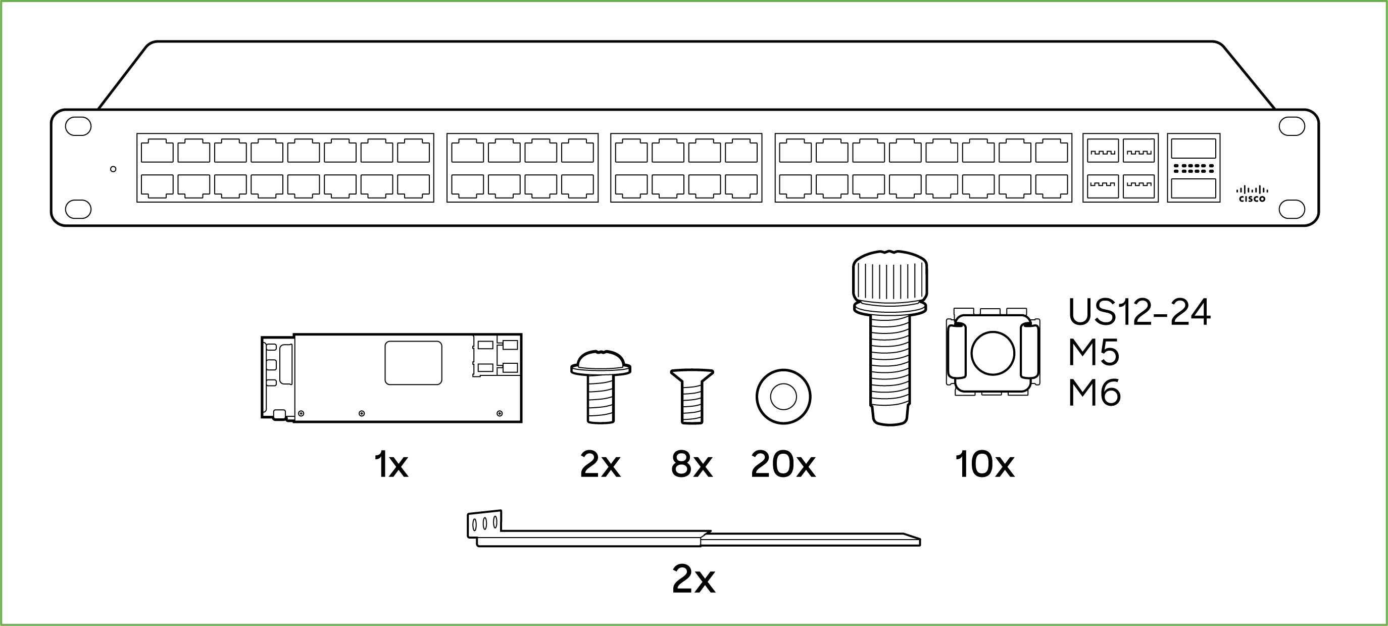
In addition to the MS switch, the following are provided (mounting kit provided with 1U models only):
- 4-post Rack Mount Kit includes:
- US 12-24 mounting screws and cage nuts, 10 of each
- INTL M5 mounting screws and cage nuts, 10 of each
- INTL M6 mounting screws and cage nuts, 10 of each
- Mounting washers
- 2 Rack mount rails
- Rail kit screws
- 1025WAC Power Supply Unit
- 3 Pre-installed Fans
Note: The MS355 does not include stacking cables. Stacking cables sold separately.
Safety and Warnings
These operations are to be taken with respect to all local laws. Please take the following into consideration for safe operation:
- Power off the unit before you begin. Read the installation instructions before connecting the system to the power source.
- Before you work on any equipment, be aware of the hazards involved with electrical circuitry and be familiar with standard practices for preventing accidents.
- Read the mounting instructions carefully before beginning installation. Failure to use the correct hardware or to follow the correct procedures could result in a hazardous situation to people and damage to the system.
- This product relies on the building’s installation for short-circuit (overcurrent) protection. Ensure that the protective device is rated not greater than: 15 A, 125 Vac, or 10A, 240 Vac.
- Please only power the device with the provided power cables to ensure regulatory compliance.
Pre-install Preparation
You should complete the following steps before going on-site to perform an installation.
Configure your Dashboard Network
The following is a brief overview only of the steps required to add a switch to your network. For detailed instructions about creating, configuring and managing Meraki networks, refer to the online documentation (documentation.meraki.com).
- Login to http://dashboard.meraki.com. If this is your first time, create a new account.
- Find the network to which you plan to add your switches or create a new network.
- Add your switches to your network. You will need your Meraki order number (found on your invoice) or the serial number of each switch, which looks like Qxxx-xxxx-xxxx, and is found on the bottom of the unit. You will also need your Enterprise license key, which you should have received via email.
- Go to the map / floor plan view and place each switch on the map by clicking and dragging it to the location where you plan to mount it.
Check and Set Firmware
To ensure your switch performs optimally immediately following installation, it is recommended that you facilitate a firmware upgrade prior to mounting your switch.
- Attach your switch to power and a wired Internet connection.
- The switch will turn on and the power LED will glow solid orange.
- If the unit requires an upgrade, the power LED will begin blinking white until the upgrade is complete, at which point the LED will turn solid white. You should allow at least a few minutes for the firmware upgrade to complete, depending on the speed of your internet connection.
Check and Configure Upstream Firewall Settings
If a firewall is in place, it must allow outgoing connections on particular ports to particular IP addresses. The most current list of outbound ports and IP addresses for your particular organization can be found on the firewall configuration page in your dashboard.
Assigning an IP Address
All switches must be assigned routable IP addresses. These IP addresses can be dynamically assigned via DHCP or statically assigned.
Dynamic Assignment
When using DHCP, the DHCP server should be configured to assign a static IP address for each MAC address belonging to a Meraki switch. Other features of the network, such as 802.1X authentication, may rely on the property that the switches have static IP addresses.
Static Assignment
Static IPs are assigned using the local web server on each switch. The following procedure describes how to set the static IP:
- Using a client machine (e.g., a laptop), connect to the switch over a wired connection.
- Using a web browser on the client machine, access the switch’s built-in web server by browsing to http://my.meraki.com. Alternatively, browse to http://1.1.1.100
- Click on the “Uplink Configuration” tab. Log in. The default login is the serial number (e.g. Qxxx-xxxx-xxxx), with no password (e.g., Q2DD-551C-ZYW3).
- Configure the static IP address, net mask, gateway IP address and DNS servers that this switch will use on its management connection.
- If necessary, reconnect the switch to the LAN.
Static IP via DHCP Reservations
Instead of associating to each Meraki switch individually to configure static IP addresses, an administrator can assign static IP addresses on the upstream DHCP server. Through “DHCP reservations,” IP addresses are “reserved” for the MAC addresses of the Meraki switches. Please consult the documentation for the DHCP server to configure DHCP reservations.
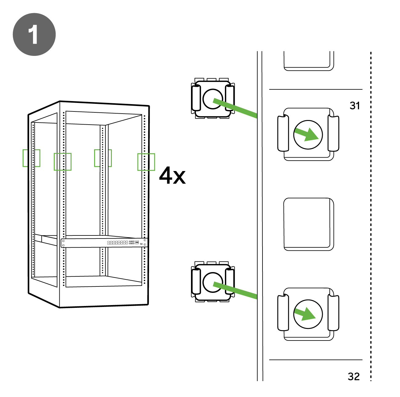
Installation Instructions
Note: Each MS355 comes with an instruction pamphlet within the box. This pamphlet contains detailed step by step guides and images to assist in the physical install of the switch.
1. Install the mounting cage nuts in the rack being used for the switch.
2. Separate the rack mount rails, and install the rack mount rails channel onto the rack.

3. Attach the rack mount rail to the sides of the switch.
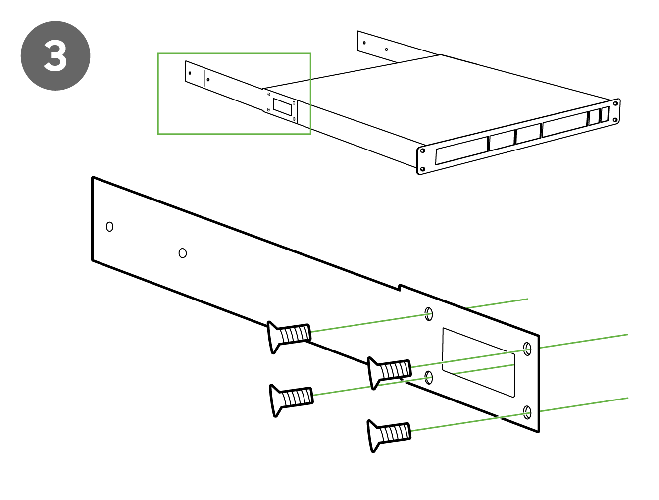
4. Insert the rack mount rail into the rack mount rail channel.

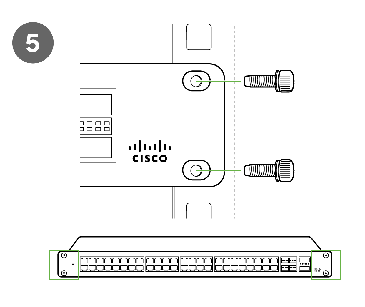
5. Attach the switch face plate to the cage nuts on the rack.
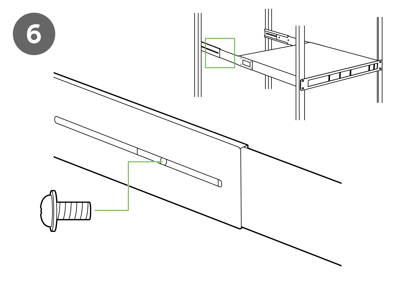
6. Secure the rack mount rail to the rack mount rail channel.
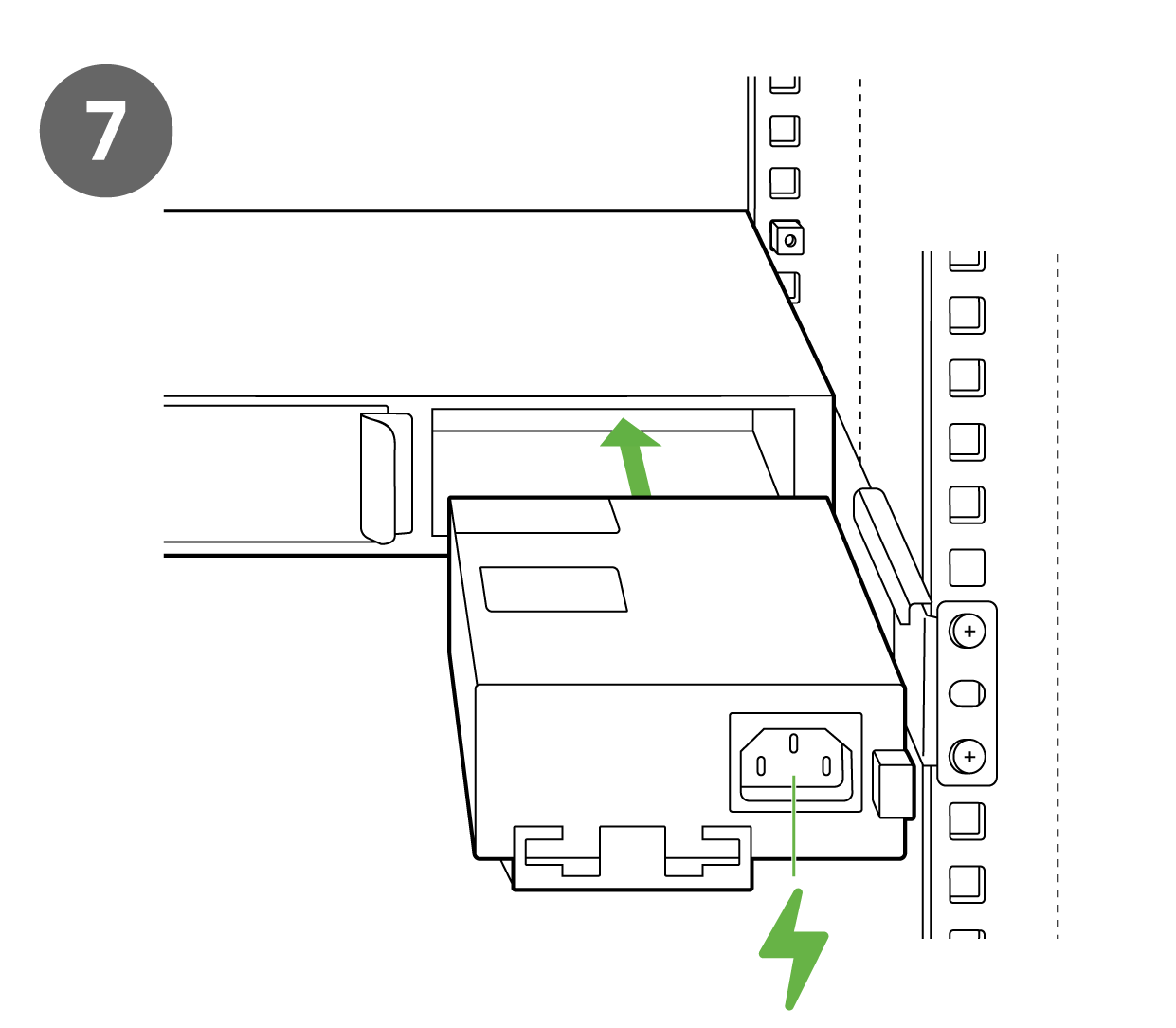
7. Insert the power supply unit into the back of the switch. After it has been securely installed, you can connect power to the power supply unit.
8. (Optional) Install additional SFP+, QSFP+ or QSFP28 units as needed, depending on the compatibility of your model.
Basic Troubleshooting
The following steps can be used for troubleshooting basic connectivity issues with your switch.
- Reset the switch
- Factory reset the switch by holding the factory reset button for 5 seconds
- Try switching cables, or testing your cable on another device
If your switch still does not connect, the following link may be useful, depending on your issue: Troubleshooting an MS Switch
Reference https://documentation.meraki.com/MS for additional information and troubleshooting tips.
If you are still experiencing hardware issues, please contact Cisco Meraki support by logging in to dashboard and using the Help option near the top of the page, then opening and email case or calling using the contact information on that page.
Bringing your Stack Online
MS355 switches can be connected in a physical stack using dedicated stacking ports and cables. Configuration steps and additional information about stacking can be found in our Switch Stacking Article.
Warranty
MS Warranty coverage periods are as follows:
| MS355 | Lifetime | |
| MS Accessories | 1 Year |
The following are considered accessories: SFP Modules, twinax/SFP+ cables, stacking cables, all mounting kits and stands, antennas, interface modules, additional power cords, PoE injectors |
Note: The above table is a general guideline for warranty terms and is not final. Warranty terms are subject to printed warranty information on the relevant online Meraki data sheets.
If your Cisco Meraki device fails and the problem cannot be resolved by troubleshooting, contact support to address the issue. Once support determines that the device is in a failed state, they can process an RMA and send out a replacement device free of charge. In most circumstances, the RMA will include a pre-paid shipping label so the faulty equipment can be returned.
In order to initiate a hardware replacement for non-functioning hardware that is under warranty, you must have access to the original packaging the hardware was shipped in. The original hardware packaging includes device serial number and order information, and may be required for return shipping.
Meraki MS355devices have been tested and found to comply with the limits for a Class A digital device, pursuant to part 15 of the FCC rules. These limits are designed to provide reasonable protection against harmful interference in a residential installation. This equipment generates, uses and can radiate radio frequency energy and, if not installed and used in accordance with the instructions, may cause harmful interference to radio communications. However, there is no guarantee that interference will not occur in a particular installation.
Additional warranty information can be found on: https://meraki.cisco.com/support#process:warranty
Support and Additional Information
If issues are encountered with device installation or additional help is required, contact Meraki Support by logging in to dashboard.meraki.com and opening a case by visiting the Get Help section.
- The equipment is intended for industrial or other commercial activities.
- The equipment is used in areas without exposure to harmful and dangerous production factors, unless otherwise specified in the operational documentation and/or on the equipment labeling.
- The equipment is not for domestic use. The equipment is intended for operation without the constant presence of maintenance personnel.
- The equipment is subject to installation and maintenance by specialists with the appropriate qualifications, sufficient specialized knowledge, and skills.
- Rules and conditions for the sale of equipment are determined by the terms of contracts concluded by Cisco or authorized Cisco partners with equipment buyers.
- Disposal of a technical device at the end of its service life should be carried out in accordance with the requirements of all state regulations and laws.
- Do not throw in the device with household waste. The technical equipment is subject to storage and disposal in accordance with the organization's disposal procedure.
- The equipment should be stored in its original packaging in a room protected from atmospheric precipitation. The permissible temperature and humidity ranges during storage are specified in the Operation (Installation) Manual.
- Transportation of equipment should be carried out in the original packaging in covered vehicles by any means of transport. The temperature and humidity during transportation must comply with the permissible established ranges of temperature and humidity during storage (in the off state) specified in the Operation Manual (Installation).
For additional information on Meraki hardware and for other installation guides, please refer to documentation.meraki.com.