Switch ACL Operation
日本語版はこちら
Access Control Lists (ACLs) can be configured on Cisco Meraki MS series switches and can be used to limit what traffic is permitted through the switch. This article will discuss how those ACLs operate based on a series of examples. For information on how to configure Meraki ACLs please see our Configuring ACLs article.
IPv6 ACLs are supported in MS firmware versions 10.0 and newer. Prior to MS 10.0, IPv4 only ACLs were configured on the Switch > IPv4 ACL page.
Currently, MS22/42/220/320 do not support IPv6 Access Lists.
Stateless Operation
ACLs configured on Meraki switches operate statelessly: each packet is evaluated individually. Thus while traffic may be allowed in one direction, the response can still be blocked. When creating ACL rules, it is important to keep this in mind and create rules that allow desired traffic in both directions.
Order of Processing
As traffic is evaluated in sequence down the list, it will only use the first rule that matches. Any traffic that doesn't match a specific allow or deny rule will be permitted by the default allow rule at the end of the list.
Any traffic passing through the switch will be evaluated. Even traffic that is not routed.
Examples
Explicit allow with explicit deny
In this example, traffic is permitted from the 10.1.10.0/24 subnet to the 192.168.20.0/24 subnet in rule 1. Any other IPv4 or IPv6 traffic will be denied by rule 2. Because of rule 2, an explicit deny, any desired traffic must be explicitly allowed to override this rule.
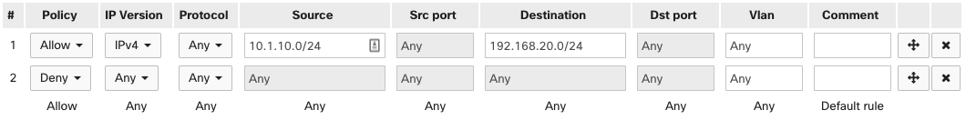
Thus if 10.1.10.50 tries to communicate with 192.168.20.20, the traffic will be allowed due to rule 1. However, the response from 192.168.20.20 will be blocked by rule 2. This occurs even though the initial communication was allowed, due to the stateless operation of the ACLs.
This will also block all communication amongst clients within the 10.1.10.0/24 network and amongst clients within the 192.168.20.0/24 network. Thus 192.168.20.20 would be unable to communicate with 192.168.20.25.
In a single rule, MS ACLs currently do not support following inputs:
- port ranges (e.g. '20000-30000')
- port lists (e.g. '80,443,3389')
- subnet lists (e.g. '192.168.1.0/24, 10.1.0.0/23')
Source VLAN
In this example, traffic from VLAN 10 is denied to any destination. This will essentially isolate any client devices in VLAN 10 and prevent them from communicating with each other or other networks. All other traffic will be permitted by the default allow at the end of the list.
Note: The VLAN qualifier is not supported on the MS390. For the MS390, ACL rules with non-empty VLAN fields will be ignored.
Note: The VLAN field refers to the source VLAN for the traffic being evaluated and is processed on ingress.

Thus 10.1.10.50 will not be able to reach 192.168.20.20. However, 192.168.20.20 will be able to send traffic to 10.1.10.50.
Traffic will also be blocked between clients within the same VLAN.
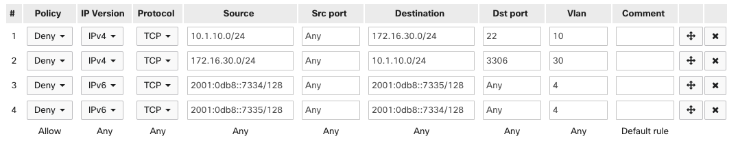
Explicit deny
In this example, VLAN 10 (10.1.10.0/24) is not permitted SSH access to any servers in VLAN 30 (172.16.30.0/24) by rule 1. VLAN 30 is not permitted MySQL access to any servers in LAN 10 by rule 2. Additionally, rules 3 and 4 prevent any communication sent between IPv6 IPs 2001:0db8::7334/128 and 2001:0db8::7335/128 on VLAN 4. All other traffic is permitted by the default allow rule.