MV52 Installation Guide
Overview
The Cisco Meraki MV52 is the first varifocal bullet camera in the second-generation smart camera family. Aligning with our other cameras, it eliminates the complex and costly servers and video recorders required by traditional solutions which removes the limitations typically placed on video surveillance deployments.
- For information on Datasheet: Click here
- For FAQ and Troubleshooting MV52: Click here
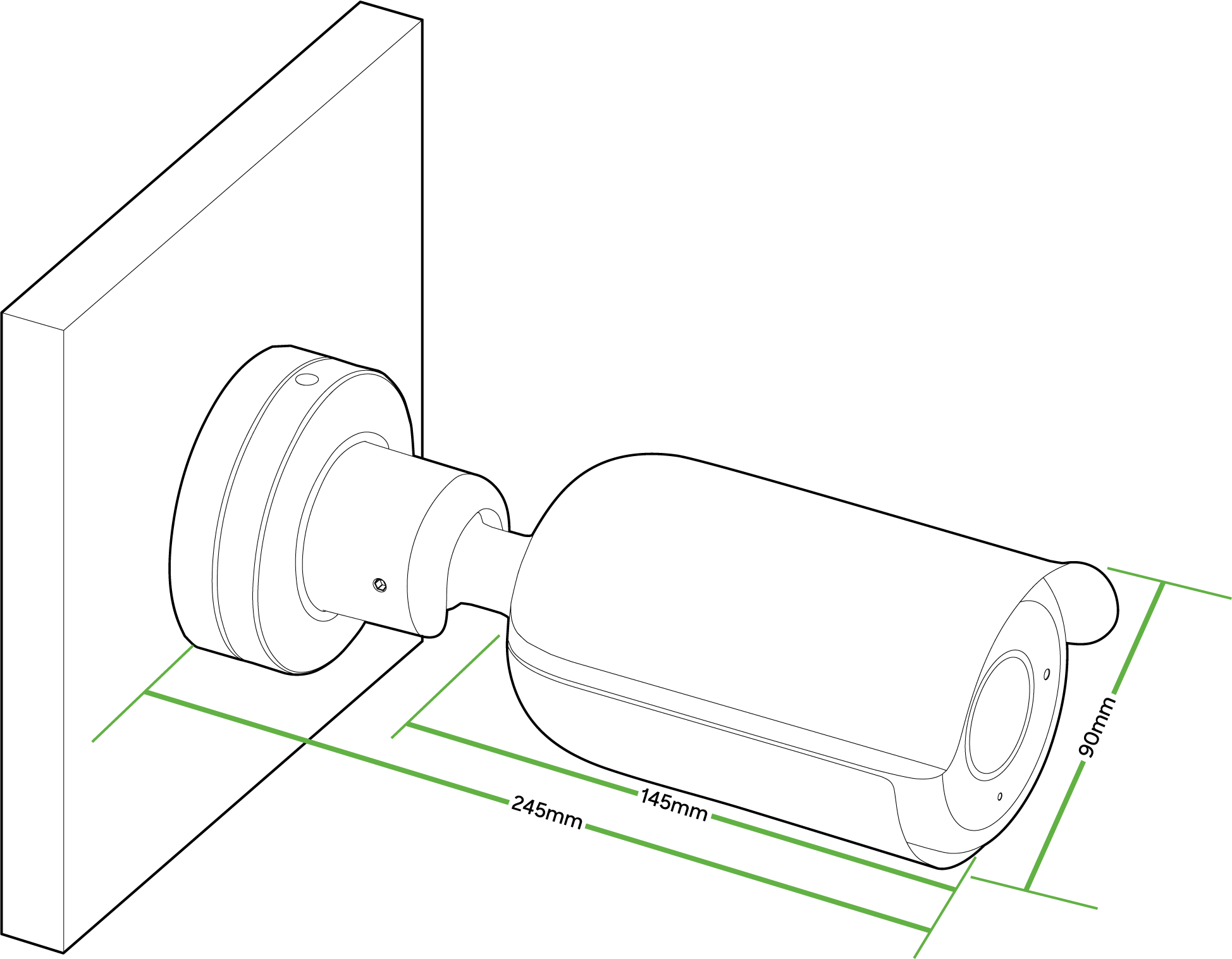
Dimensions
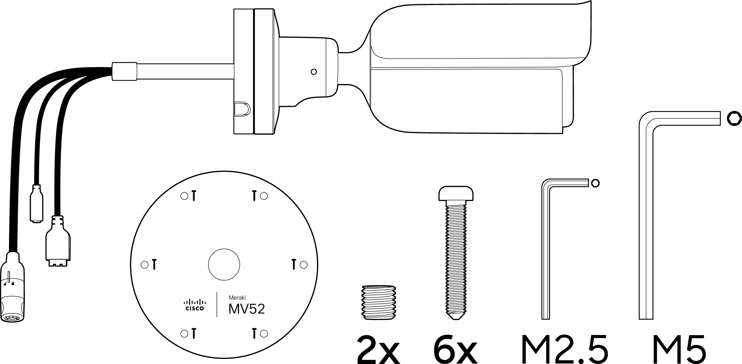
Box Contents
A single camera box contains:
-
One camera hardware
-
One mount template
-
Two set screws
-
Six screws
-
One M2.5 torx key
-
One M5 torx key
Powering the MV52
The MV52 features a 1000BASE-TX Ethernet port with 802.3at PoE+ and requires 30W of power to run. Route the Ethernet cable from an active port on a PoE switch or PoE injector. Additionally, a 12V DC input option is available as well. As seen below:
MV52 requires 30W power, dedicated entirely to itself for higher processing and IR load.
Pre-Install Preparation
Complete the following steps before going on-site to perform an installation.
Configure Your Network in Dashboard
The following briefly overviews the steps required to add an MV52 to your network. For detailed instructions about creating, configuring and managing Meraki Camera networks, refer to the online documentation (https://documentation.meraki.com/MV).
-
Navigate to http://dashboard.meraki.com. If this is your first time accessing the dashboard, create a new account.
-
Locate the network where you want to add your cameras, or create a new network.
-
Add your cameras to the network. Use your Meraki order number (found on your invoice) or the serial number of each camera. The serial number, which looks like QXXX-XXXXX-XXXX, can be found on the bottom of the camera unit.
-
Confirm the camera is listed under Cameras > Monitor > Cameras.
Check and Configure Firewall Settings
If a firewall is in place, it must allow outgoing connections on specific ports to designated IP addresses. Refer to latest list of outbound ports and IP addresses for your organization here.
DNS Configuration
Each MV52 camera generates a unique domain name for secure direct streaming. These domain names resolve to an A record linked to the camera's private IP address and can be resolved by any public recursive DNS server.
When using an on-site DNS server, allow *.devices.meraki.direct or set up a conditional forwarder. This ensures local domains are not appended to *.devices.meraki.direct and that these requests are forwarded to Google Public DNS.
Assigning IP Addresses
The MV52 does not support static IP assignment.MV52 units must be added to a subnet with DHCP enabled and available DHCP addresses for proper operation.
Install Instructions
Each MV52 includes an instruction pamphlet in the box. The pamphlet provides step-by-step guides and images to assist with the camera's physical installation.
The camera comes with a protective lens cover. Remove the lens cover before installation.
The camera operates at a high external temperature due to its advanced night mode and processing capabilities. It can reach up to 50°C when night mode is on. Mount the camera before plugging it in.
Placement Guidelines
The MV52 can be mounted in three ways:
Wall or ceiling

Pole (with accessory)
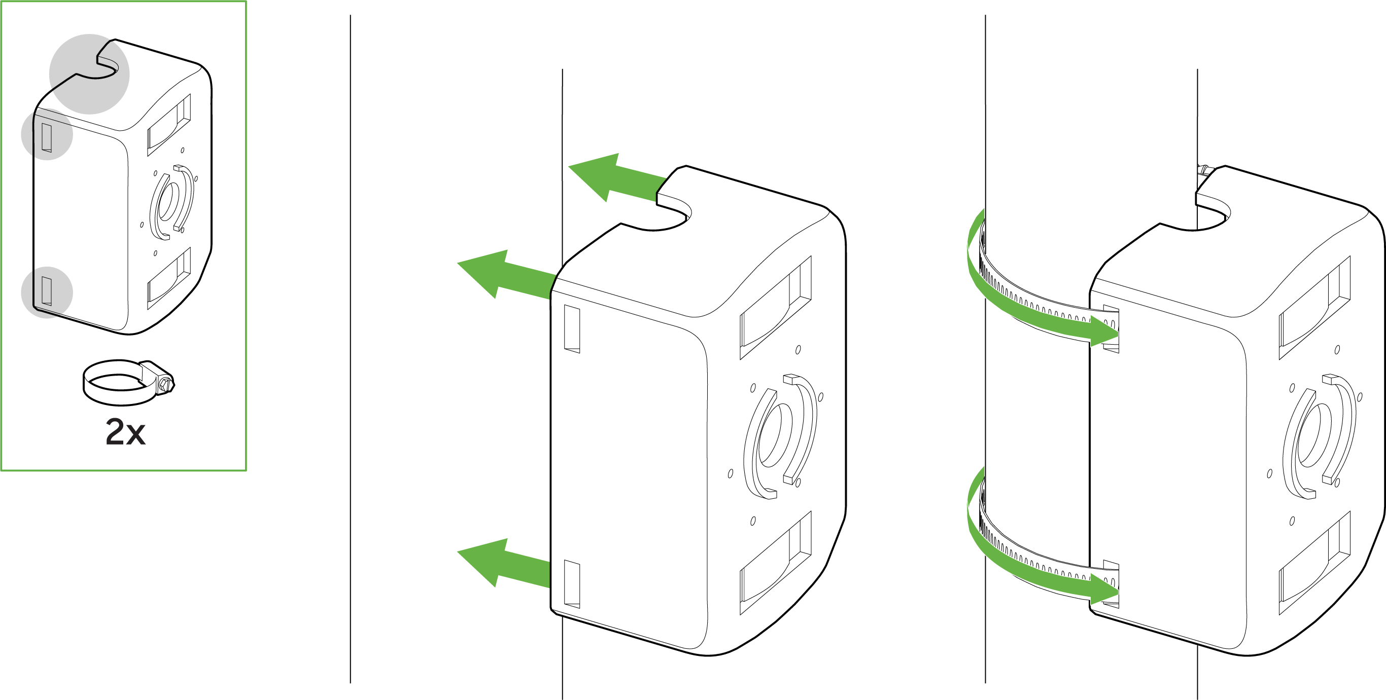
Pole mount MA-MNT-MV-21, specifically designed for MV52, is available to order separately.

The MA-MNT-MV-21 can be mounted on a pole (>40 mm currently supported) as below:
- Attach the pole mount to hug the pole
- Drag a metal cable tie around the top/bottom of this mount
Considering the weight of this camera, it is recommended to use safety cable wires.
Adjacent to a junction box (no conduit adapter-in-box)
Adjacent mounts to a 3.5'' junction box would be ideal

Mounting Instructions
Ensure that deployments of this camera are properly planned with the corresponding labour and equipment for a smooth experience.

Note that the fixed power cable will not be exposed to the outdoor environment after the successful installation of the MV52 on a wall using the above-provided pigtails.
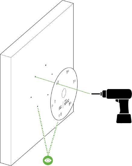
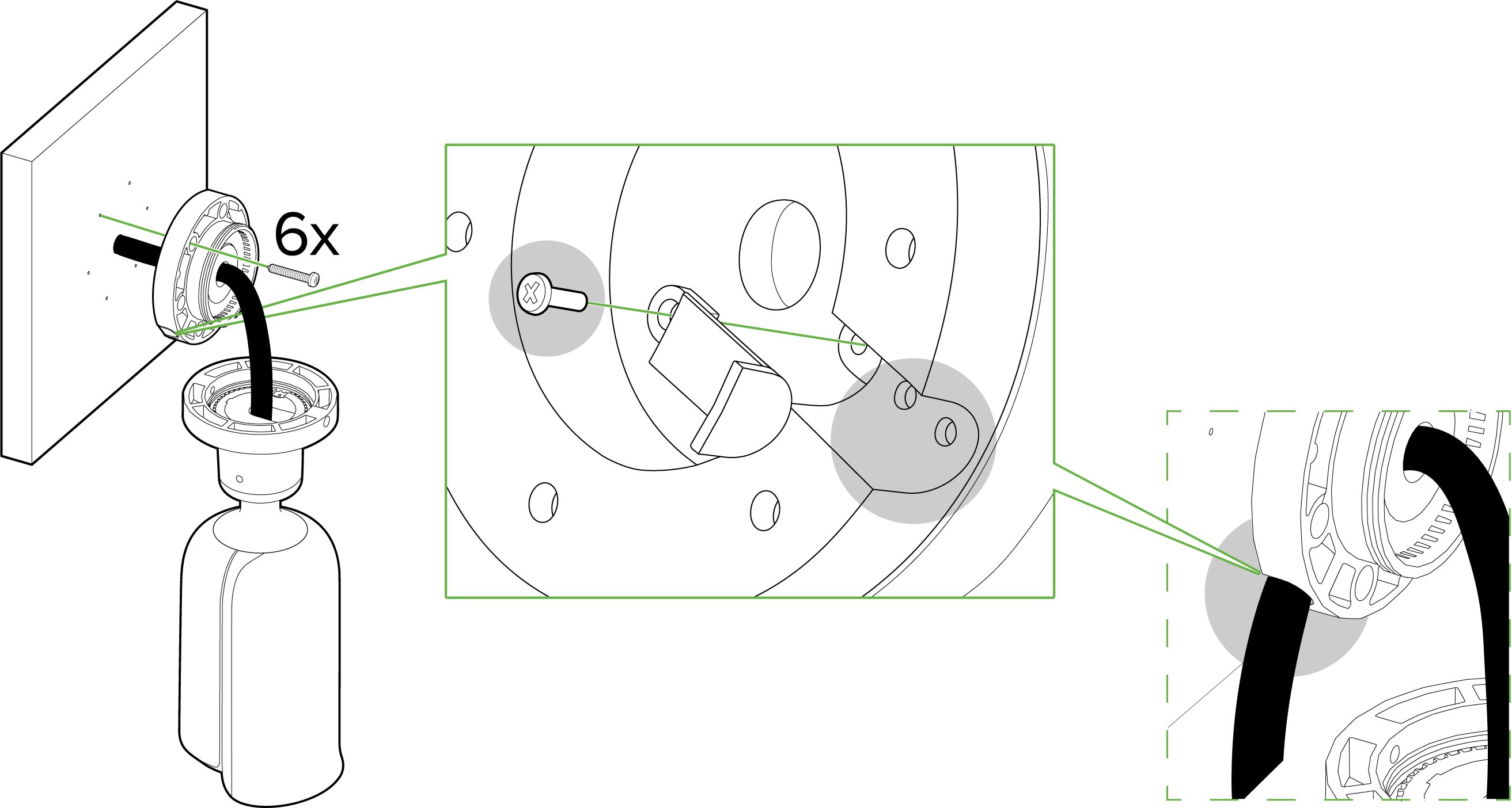
1. Place the mounting template onto the surface (wall/ceiling) and drill six holes as well as the center hole, as marked (if needed).
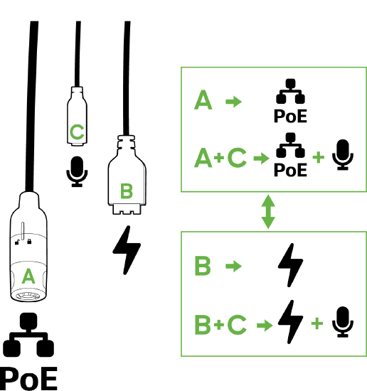
2. The following inputs are currently available for the MV52:
-
A - PoE+ input
-
B - 2 pin 12VDC input
-
C - Audio input
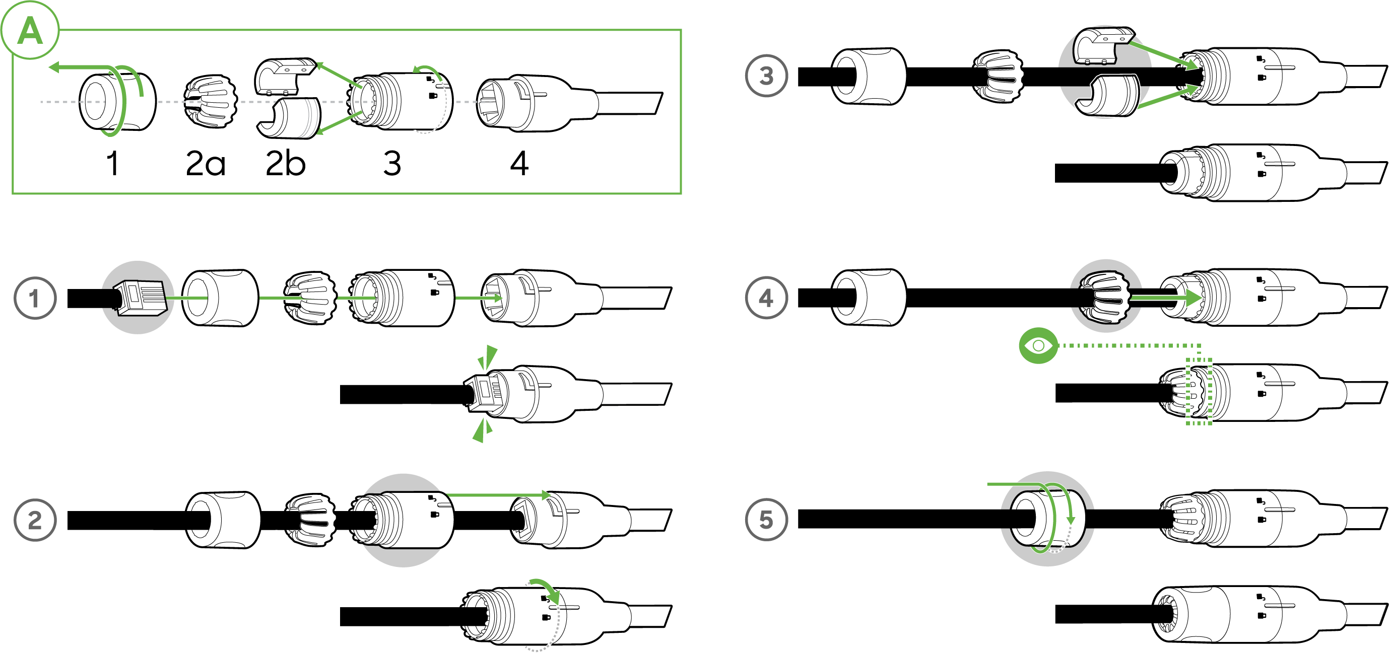
Follow this in-depth cable gland assembly guide to connect the PoE cable to the camera cable gland and ensure the seal is water-tight. This step is very important and may result in damage to the camera if done improperly.
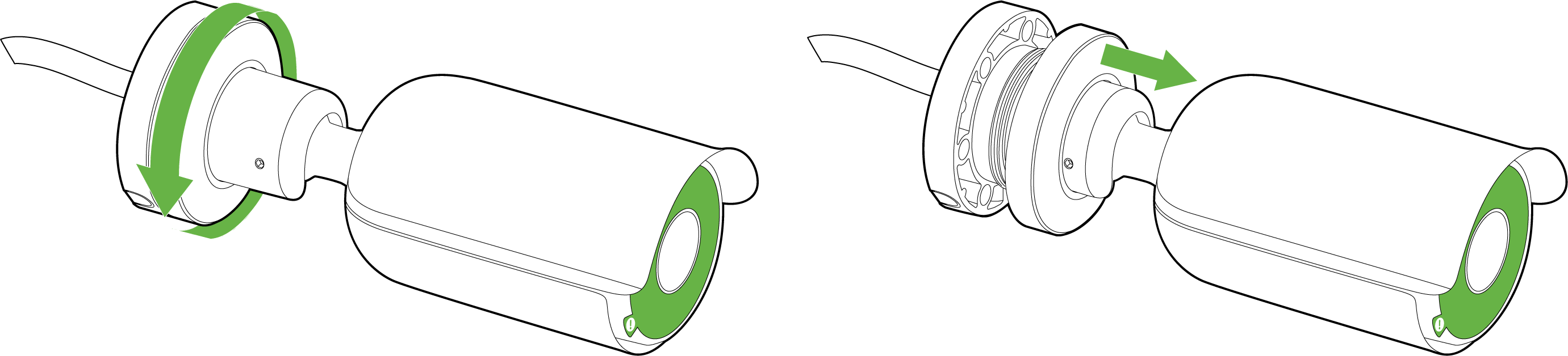
3. Pass the cable through the center hole and plug it in. Then, in an anti-clockwise direction, unscrew the top of the base from the rest of the camera.
4. To support the camera base, use the six provided screws or any screws with a head size smaller than 8.6 mm. Secure the screws into the base and the surface. You can route the cable through the wall or guide it out to the side by unscrewing the designated cut, as shown in the zoomed-in illustration.
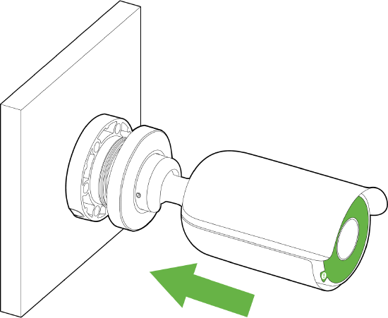
5. Grab the camera to fix it into a horizontal position, closer to the base.
6. In a clockwise motion, rotate the top of the base to affix the camera to the base, while leaving some space to rotate and aim the camera later.
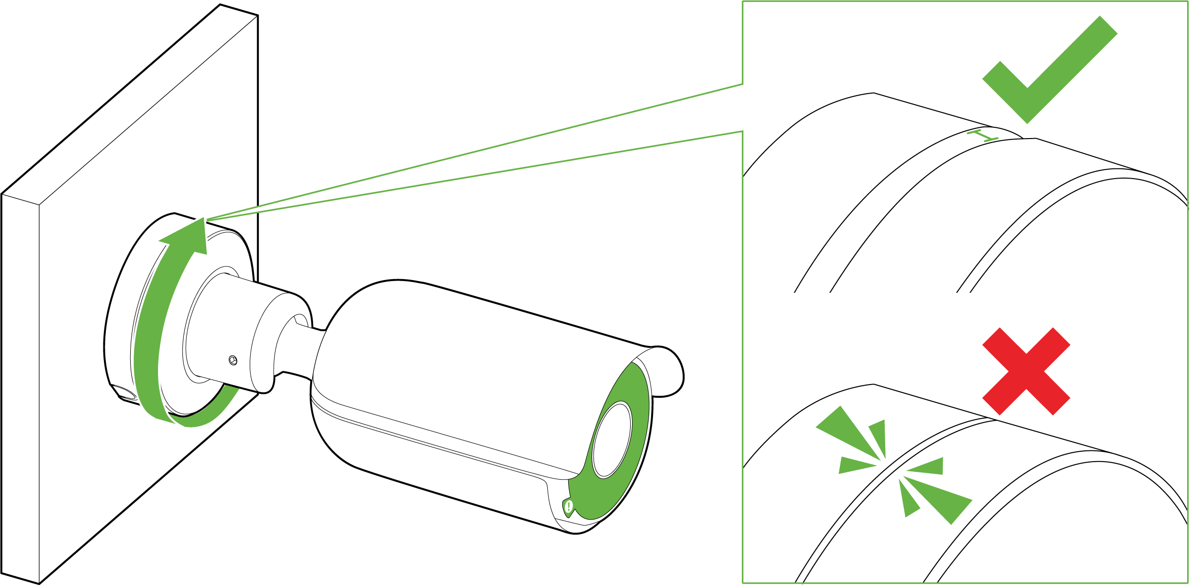
7. With the base top aligned to the base, rotate the camera using the ball joint to fix your field of view/angle. Ensure that the opening is facing the direction in which the camera needs to look, and that the hood is on the top.

Do not tighten the base before checking on the angles/view
Due to the fixed nature of the lens, only digital rotation is available from the dashboard in 180° increments.
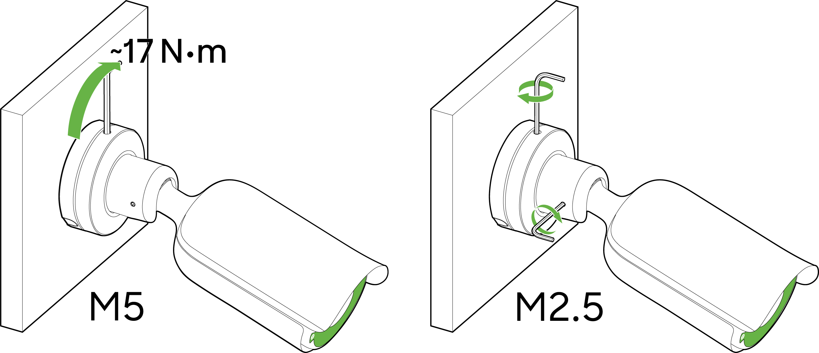
8. Tighten the top of the base clockwise once you have a confirmed position.
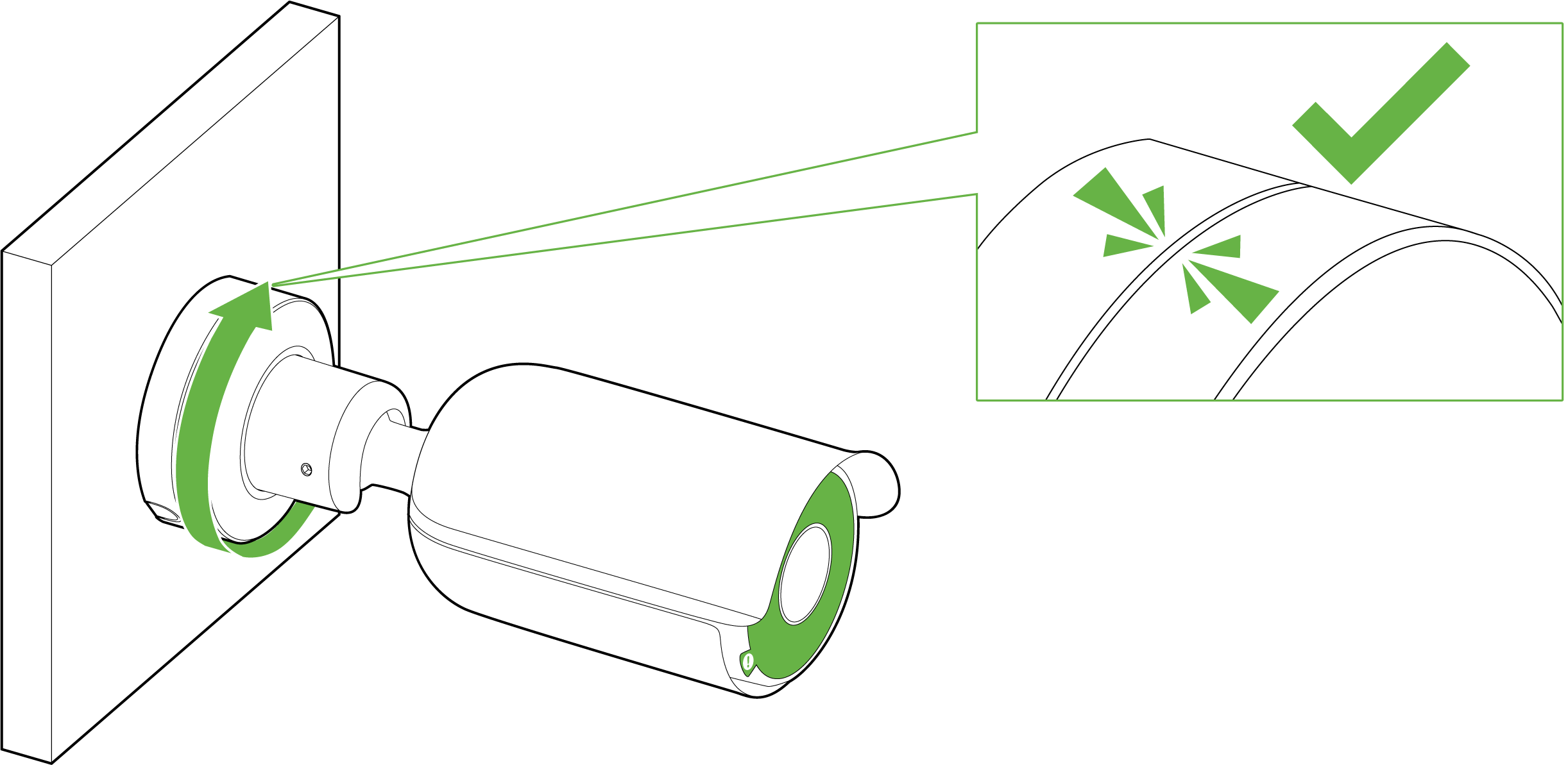
9. Tighten this even further by using the M5 and M2.5 torx keys provided around the joint and the top of the base.
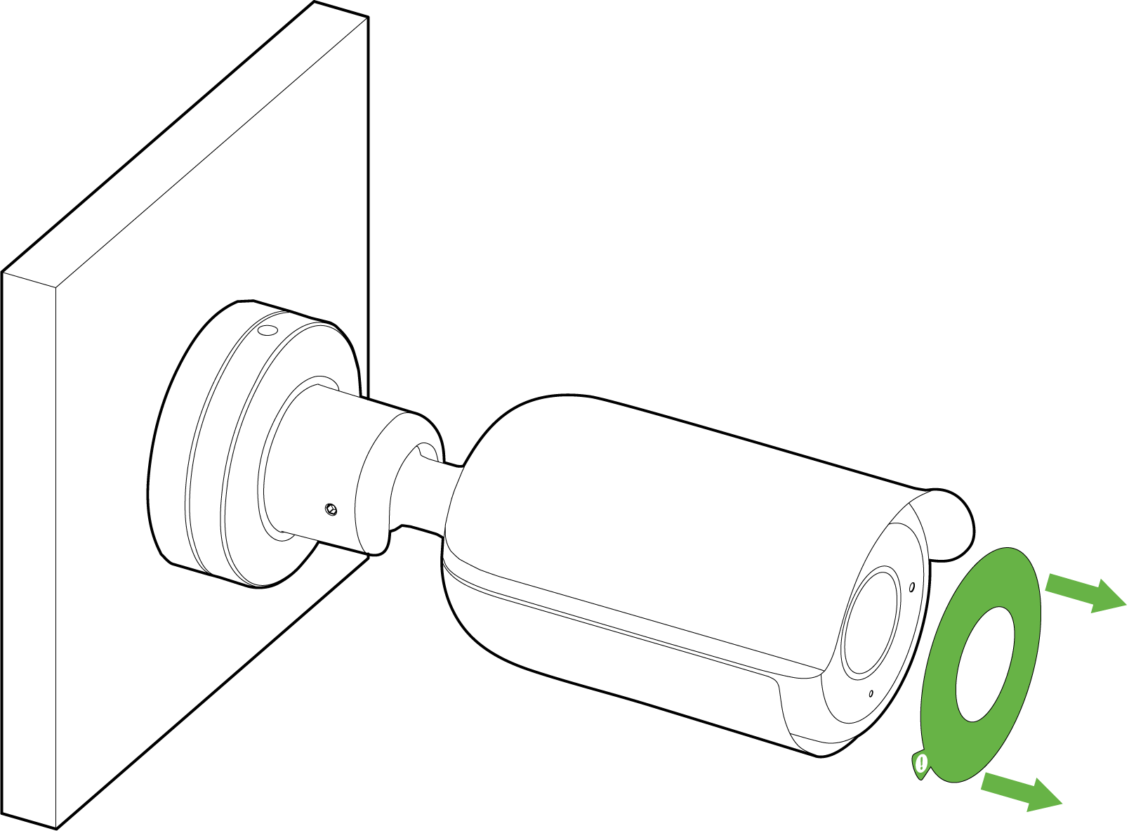
10. Remove the green IR safely label once you have finished positioning your MV52.
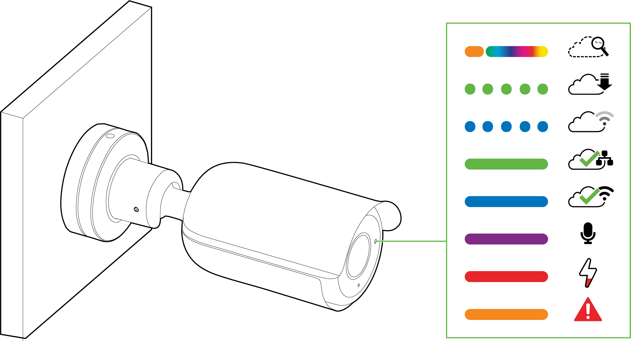
LED Indicator
The various status conditions of an MV are indicated by the following colors and patterns:
- Rainbow (solid, rotating through colors) - MV is booting up.
- Flashing Blue - MV is searching for WiFi network(s).
- Flashing Green - MV is upgrading or initializing for the first time.
- Solid Green - MV is connected via Ethernet.
- Solid Blue - MV is connected via WiFi.
- Solid Violet - MV has audio recording enabled.
- Solid Amber - MV has a network issue and cannot talk to dashboard
- Solid Red - Power connection is below <7.8V