
MV Outdoor Series Waterproof Gland Installation
Throughout this guide, refer to the images for an example and read the entire paragraph of each step before proceeding.
You can also watch the video on YouTube.
Prepare for Installation
The camera's pigtail and waterproof gland are designed to protect against temporary immersion of water and not prolonged exposure. Prolonged exposure can cause corrosion of the cable and thus hardware failure. Utilization of conduit and junction boxes to protect the cable is advised. Verify the cable gland is sealed properly after installation.
When setting up the camera at a high point like a ladder, secure a method to hold the loose gland pieces using a flat surface on the ladder top, a tray, a small pouch, tape, or your overalls.
-
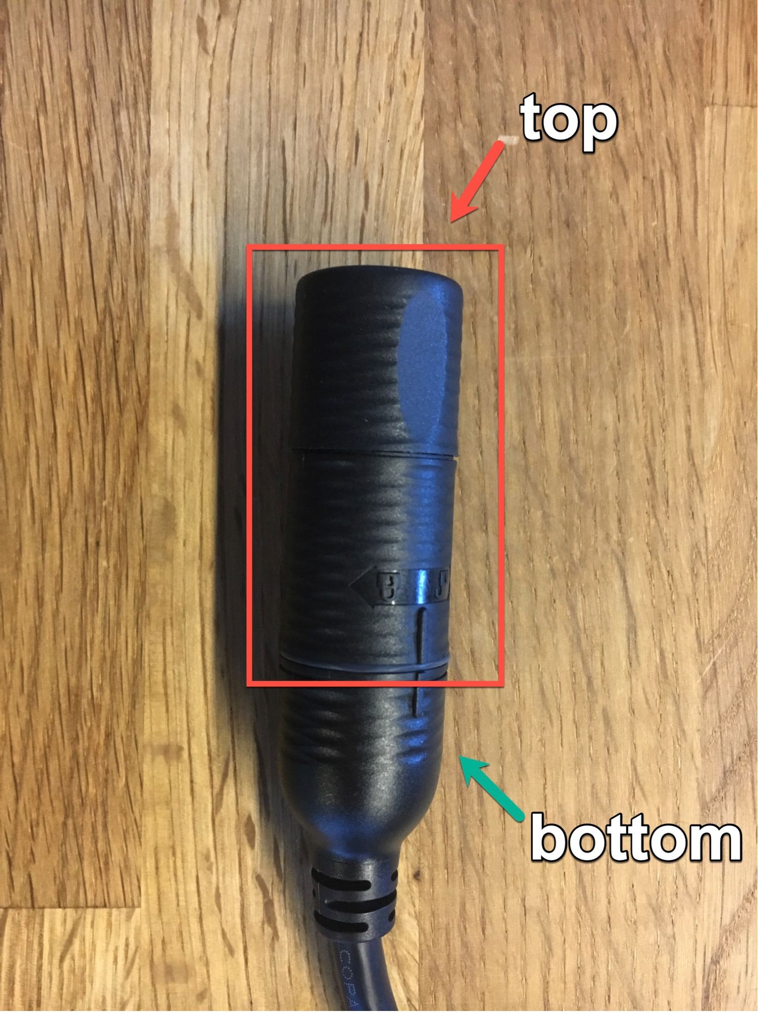
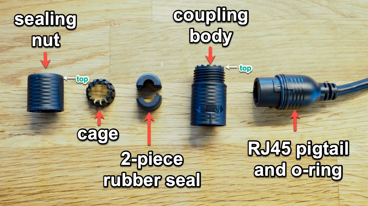
The four (4) main pieces come assembled in the box. You can find the 4 pieces within the section labeled “top” in the diagram below. Remember this orientation for the next steps.
-
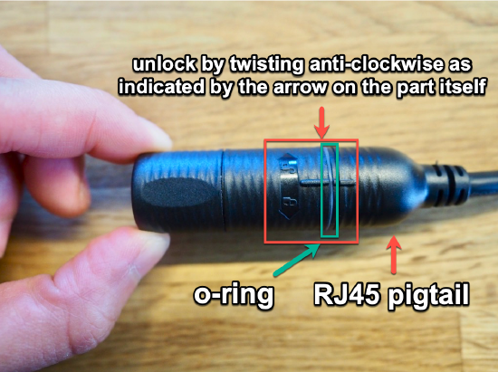
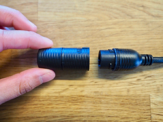
To separate the top and bottom, start by tightly gripping the bottom RJ45 pigtail (bottom) in one hand and the top part in the other. Twist the top counter-clockwise to unlock it from the RJ45 pigtail as shown. Make sure that the rubber o-ring that was in between the top and the pigtail stays on the pigtail. You can set aside the pigtail for the first few steps of the assembly.
-
After ensuring that you have a reliable way of placing loose pieces, hold the top part upright with the larger opening at the bottom to ensure that pieces do not fall out. Then, carefully unscrew the top part to separate this into two (2) coupled pieces: the sealing nut and the coupling body. Inside you will see the final two (2) smaller pieces: the cage and the 2-piece rubber seal.
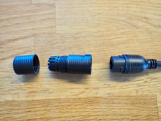
Let’s call the four (4) main pieces the sealing nut, the cage, the 2-piece rubber seal and the coupling body. They are labeled in the diagram below along with the RJ45 pigtail and o-ring.
Assemble the Gland
General Assembly Diagram
(as shown inside the MV72 box)
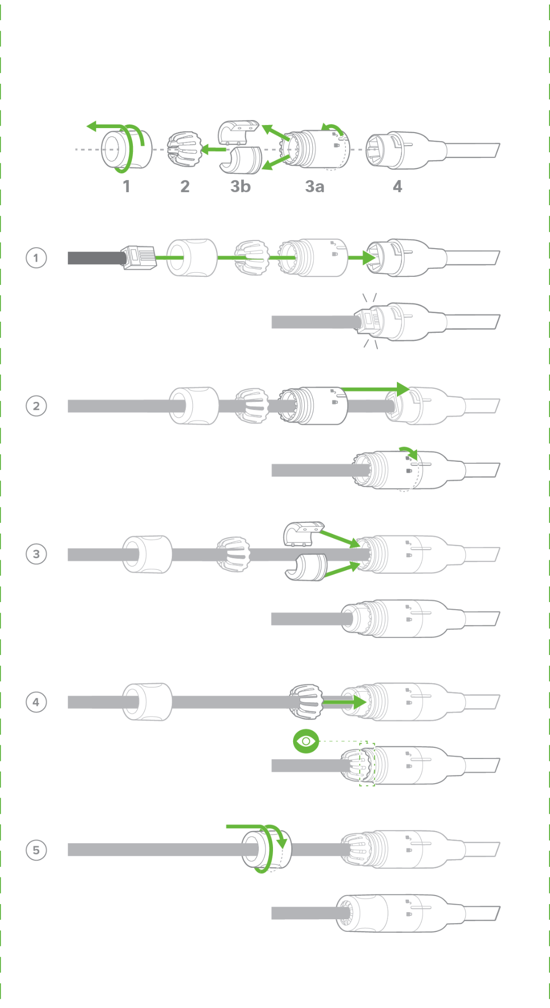
Assembly Breakdown
-
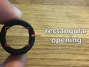
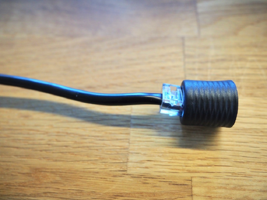
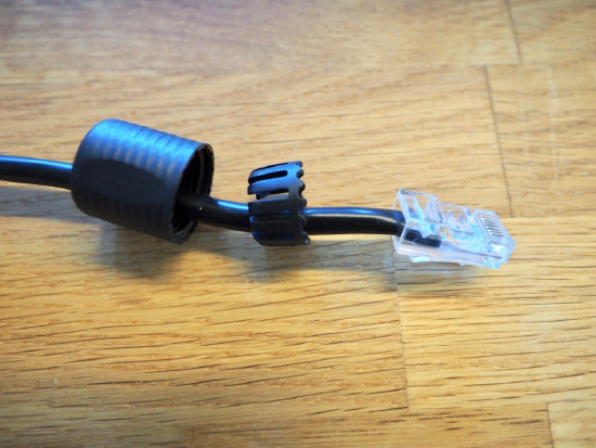
Prepare your patch cable with an RJ45 Ethernet connection. Start by inserting the end of the cable into the top of the sealing nut which has a rectangular opening.
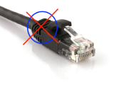
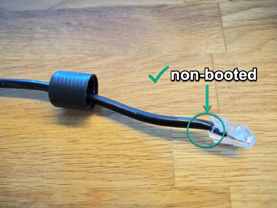
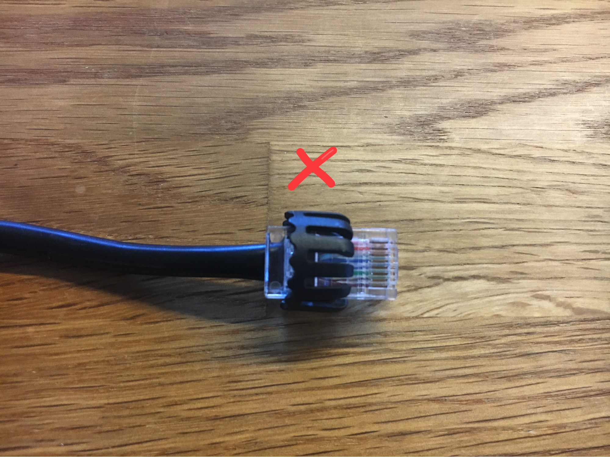
IMPORTANT: Do not use booted patch cables as the pieces will not fit.
Make sure to use standard Cat 5, 5e, 6, 6a or 7 cables (Non-Booted only)
-
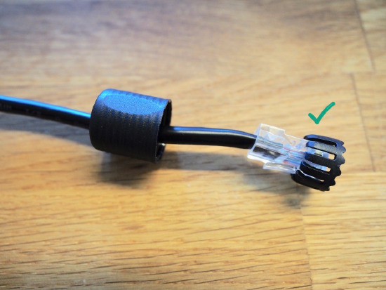
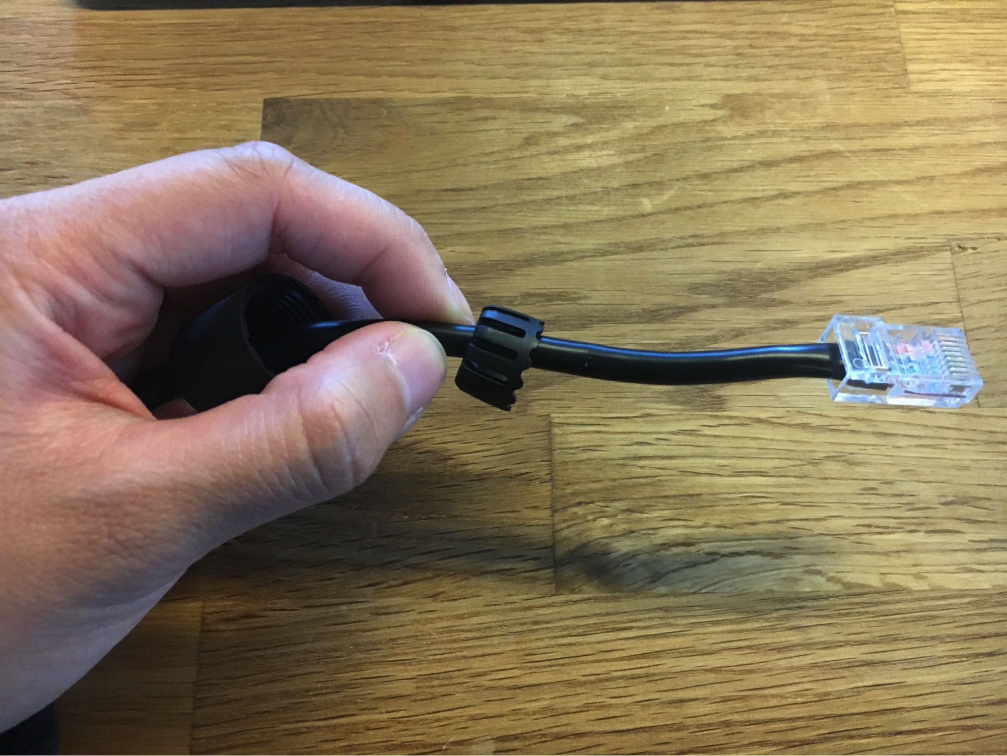
Next, put the cage on (claws first) over the patch cable end. Ensure you do not bend the claws too much while you work the claws over the plug. Afterward, hold the cable tightly on one hand in between the cage and the sealing nut to prevent these two pieces from getting stuck (ensure the end is still exposed).
TIP: If they do get stuck, use a pointed end to carefully push the claws of the cage from the top of the sealing nut. Work your way around the edges of the hole as you push.
-
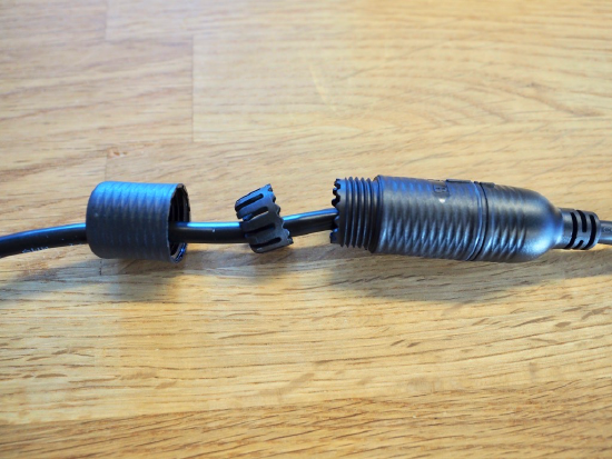
With your other hand still holding the cable in between the sealing nut and the cage as shown, now put the patch cable through the coupling body, starting with the top end (which outlines an RJ45 and also has external threads).
-
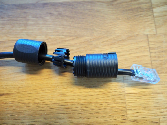
Plug the patch cable into the RJ45 pigtail on the camera.
-
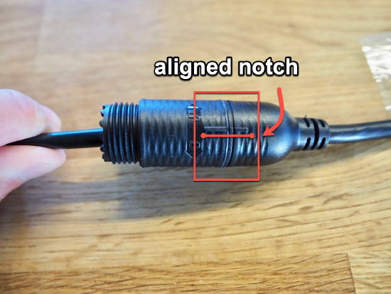
Slide the coupling body over the head of the patch cable (now plugged in) and then twist to lock and align to the notches on the plastic sides. Make sure the o-ring is still present.
-
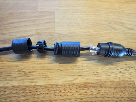
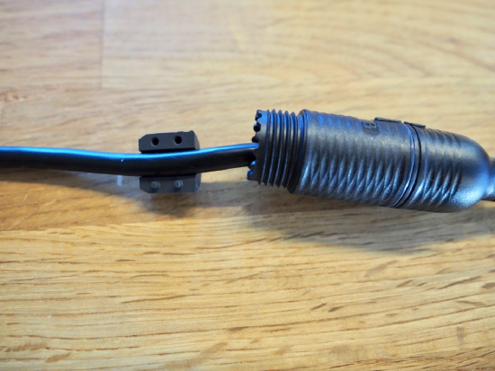
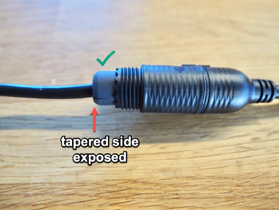
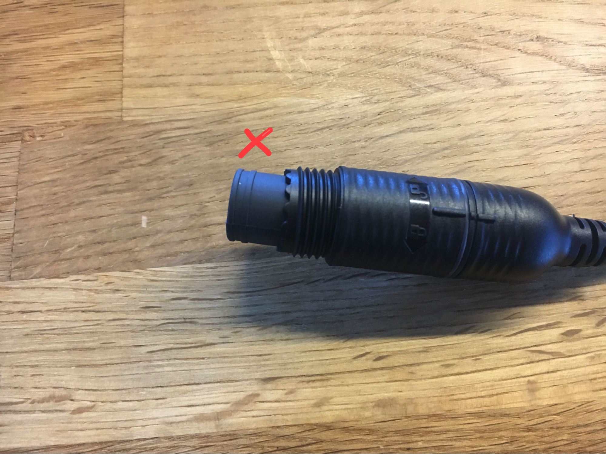
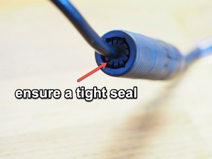
Put the two smaller pieces of rubber seal around the cable and then, tapered side exposed, firmly push it into the end of the exposed coupling body to make sure it is tightly sealed.
-
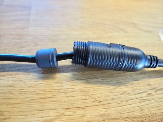
Slide the cage over the rubber seal and align the teeth of the cage to the coupling body. Make sure it stays in place.
-
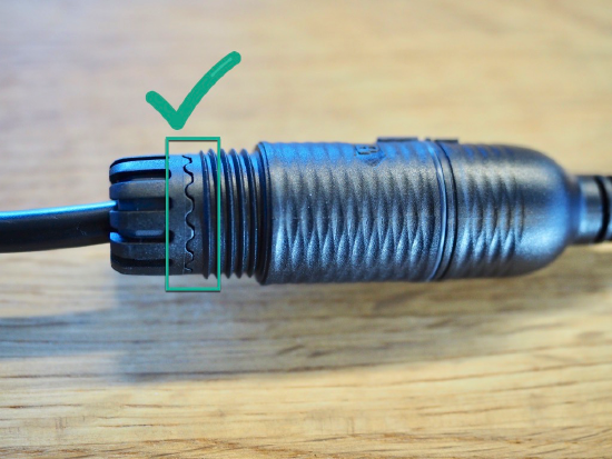
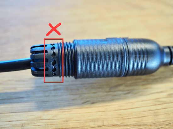
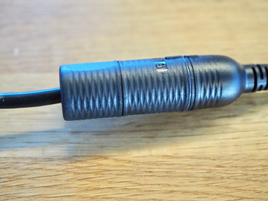
Finally, slide the sealing nut over the cage and tightly screw it into the coupling body to create a seal with the cage and rubber seal. The sealing nut and the cage will compress the rubber seal around the cable to protect it from the elements. The claws of the cage should be evenly arranged around the opening of the sealing nut.
-
IMPORTANT: Ensure that you replace the desiccant packet inside of the camera dome. Note: The desiccant pack is a small, rectangular, white packet that is used to absorb moisture.
-
OPTIONAL: For extra protection, you can use self-amalgamating or self-fusing tape around the top of the sealing nut to further ensure everything stays sealed.