
MV71 Installation Guide
MV71 Overview
The Cisco Meraki MV71 series is an IP66/IK10 rated network cameras are easy to set up and configure. They integrate with the Meraki Dashboard and use cloud-augmented edge storage. The MV family eliminates the need for complex and expensive servers and video recorders, eliminating the typical limitations of traditional video surveillance deployments.
Package Contents
In addition to the MV camera, the following are provided:
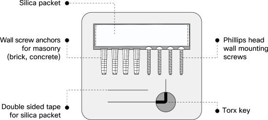
Torx Key: Secure T10.
Ethernet Port
The MV71 features a 100BASE-TX Ethernet port that supports 802.3at PoE+.
Pre-Install Preparation
You should complete the following steps before going on-site to perform an installation.
Configure Your Network in Dashboard
The following is a brief overview of the steps to add an MV71 to your network. For detailed instructions on setting up, configuring, and managing Meraki Camera networks, refer to the online documentation (https://documentation.meraki.com/MV).
-
Log in to http://dashboard.meraki.com. If this is your first time accessing the dashboard, create a new account.
-
Locate the network to which you plan to add your cameras, or create a new network if needed.
-
Add your cameras to the selected network. To do this, you will need either your Meraki order number (found on your invoice) or the serial number of each camera. The serial number, which looks like Qxxx-xxxx-xxxx, can be found on the bottom of the camera unit.
-
Verify that the camera has been successfully added by checking under Cameras > Monitor > Cameras.
Check and Configure Firewall Settings
If a firewall is in place, it must allow outgoing connections on specific ports to designated IP addresses. Refer to latest list of outbound ports and IP addresses for your organization here.
Configuring DNS
Each MV71 camera generates a unique domain name for secure direct streaming. These domain names resolve to an A record linked to the camera's private IP address and can be resolved by any public recursive DNS server.
When using an on-site DNS server, allow *.devices.meraki.direct or set up a conditional forwarder. This ensures local domains are not appended to *.devices.meraki.direct and that these requests are forwarded to Google Public DNS.
Assigning IP Addresses
The MV71 does not support static IP assignment. MV71 units must be added to a subnet with DHCP enabled and available DHCP addresses for proper operation.
Installation Instructions
Each MV71 includes an instruction pamphlet in the box. The pamphlet provides step-by-step guides and images to assist with the camera's physical installation. A PDF version of the pamphlet is available here.
During the initial setup, the MV71 automatically updates to the latest stable firmware. Some features will be unavailable until the update is complete. This process can take up to 10 minutes due to enabling whole disk encryption.
Install the MV71
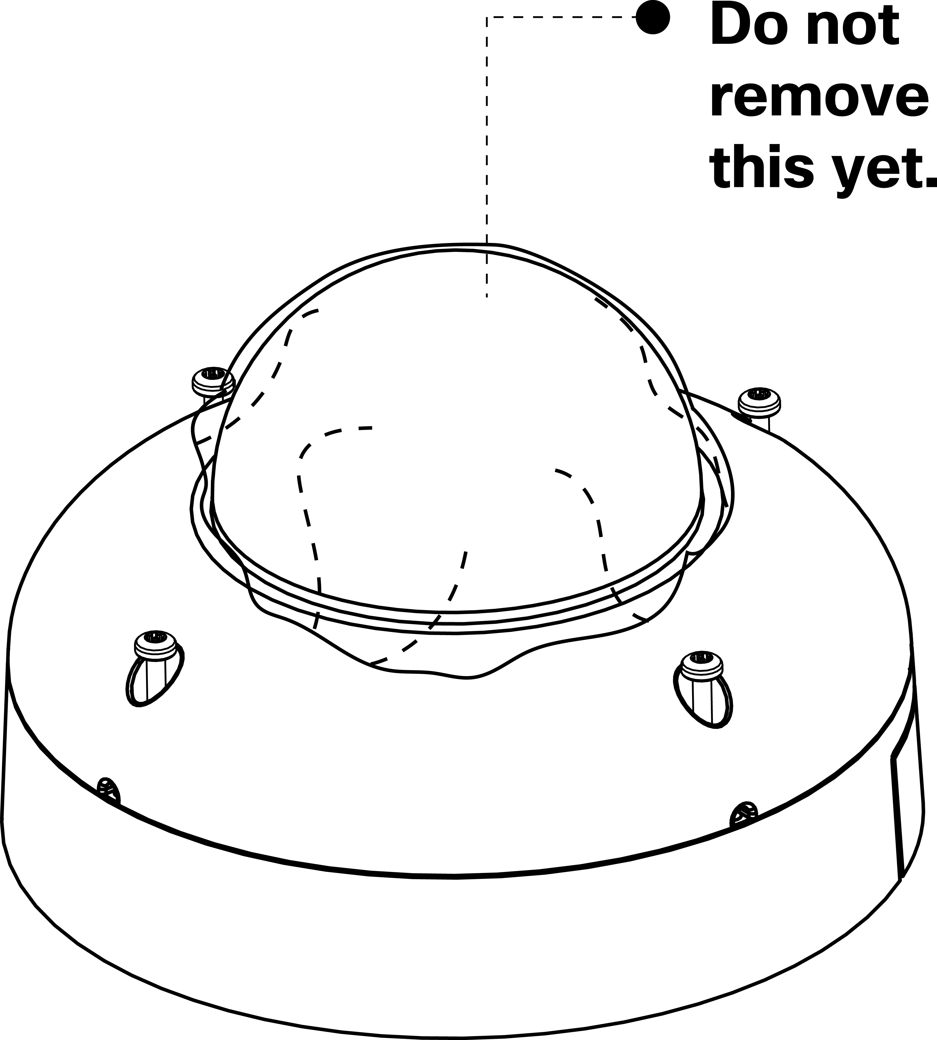
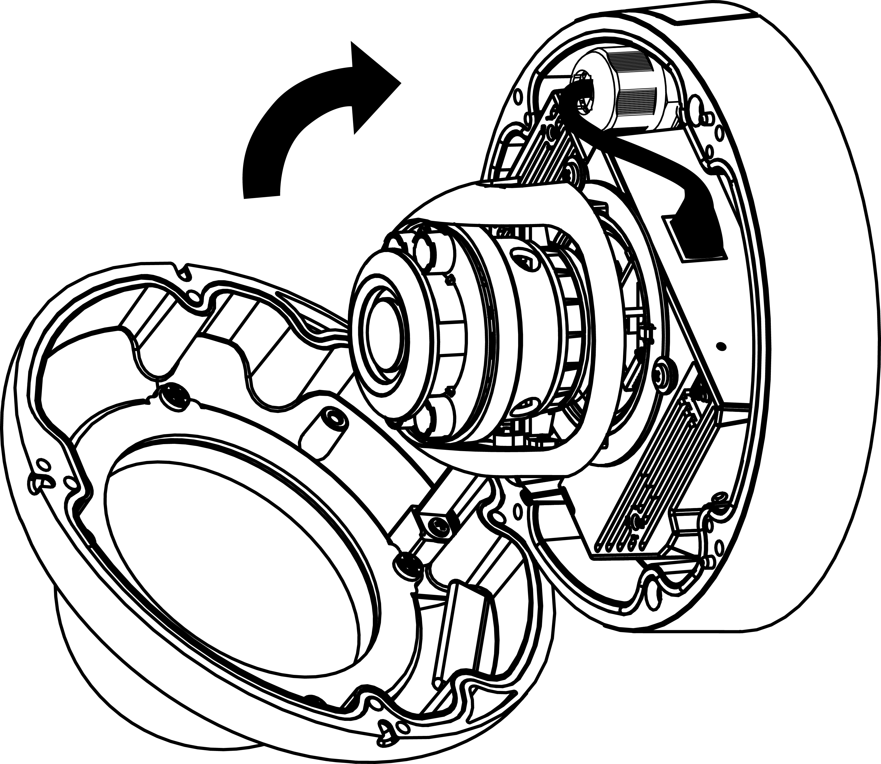
1. Leave the protective plastic sticker on camera bubble. Loosen the four exterior Torx screws to open the dome cover using the provided Torx wrench.
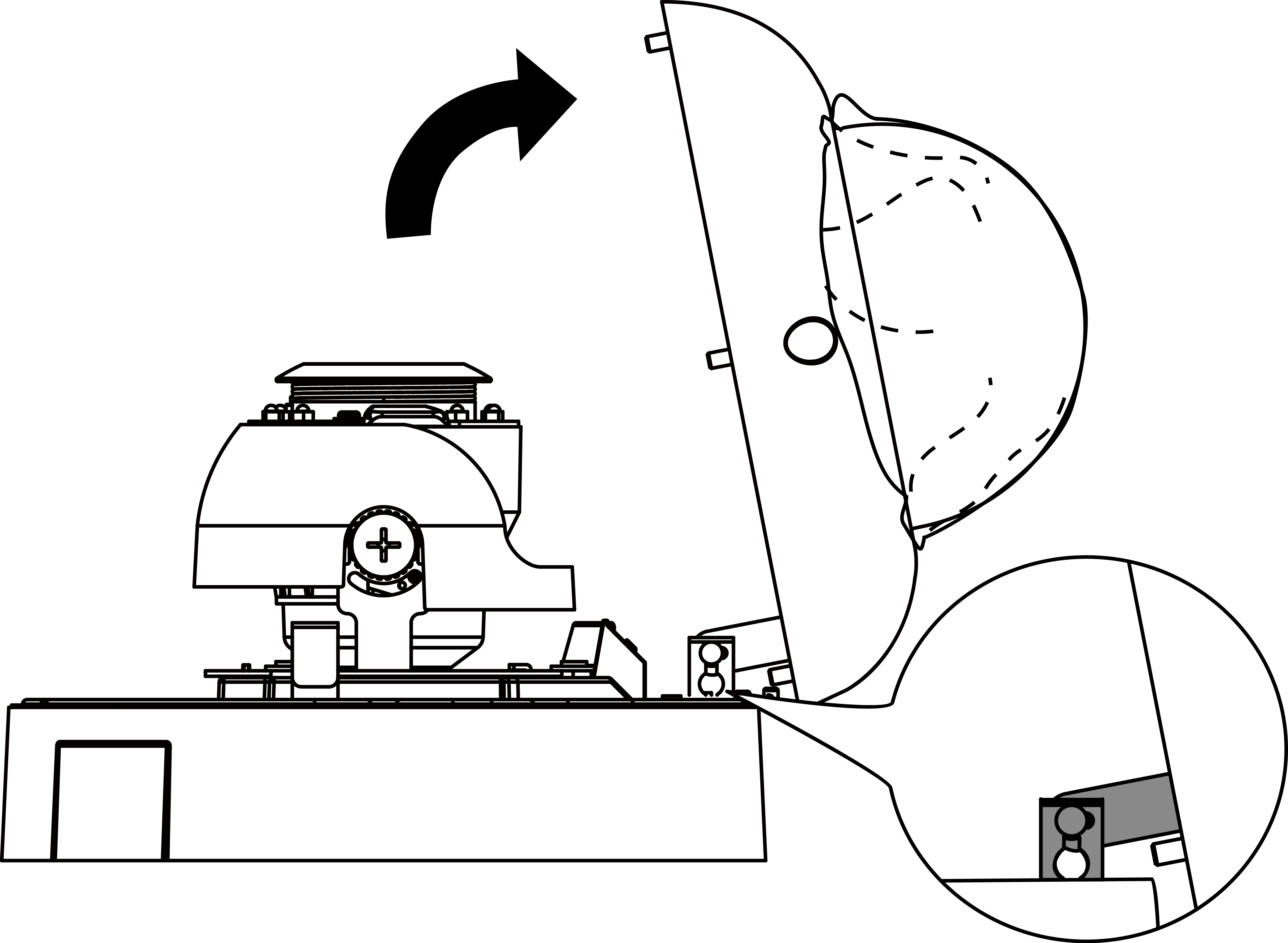
2. Hinge the dome cover off of the base and detach it from the dome cover retainer bracket before installing camera.
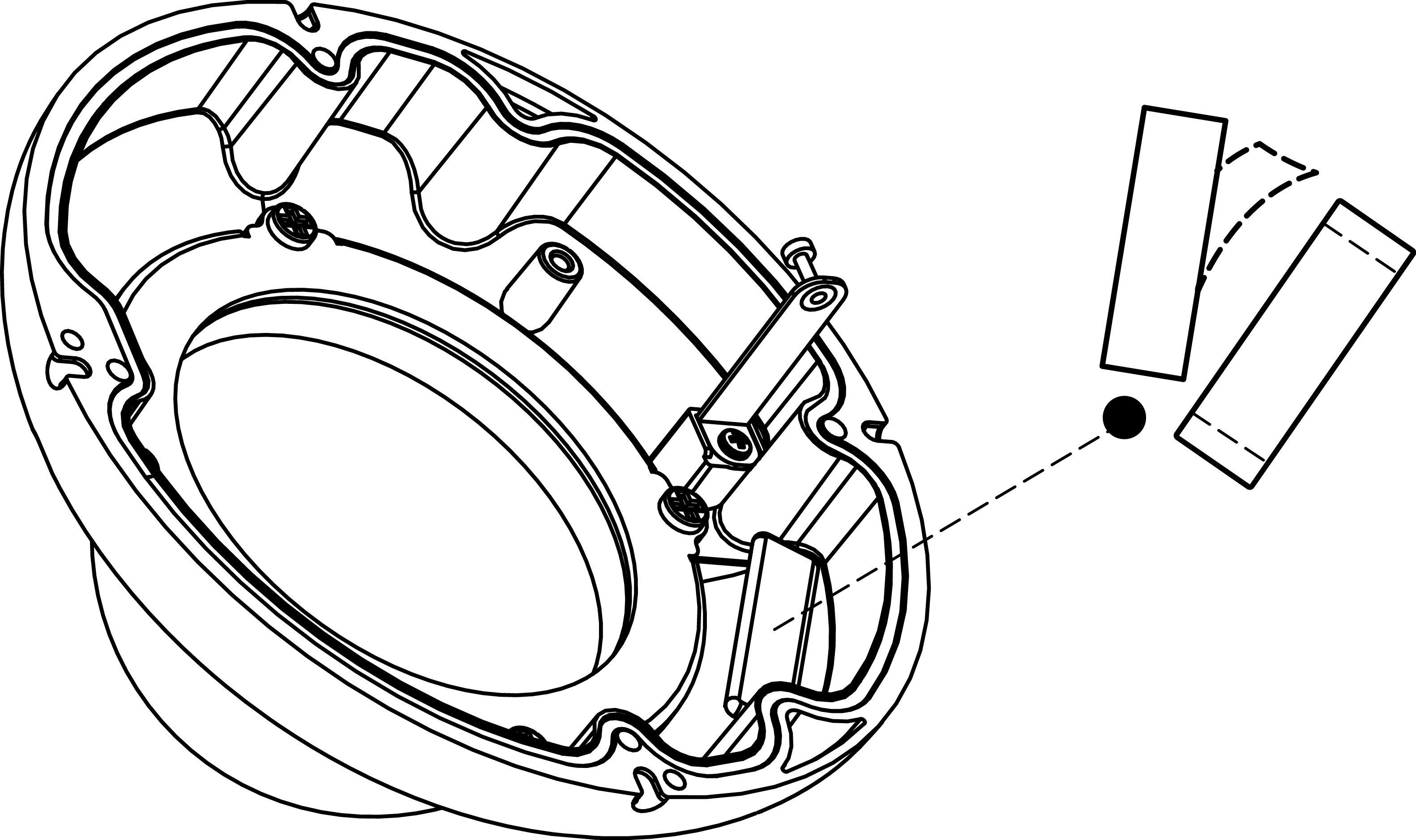
3. Replace the existing silica packet with the fresh silica packet using the double sided tape provided in the installation accessories kit.
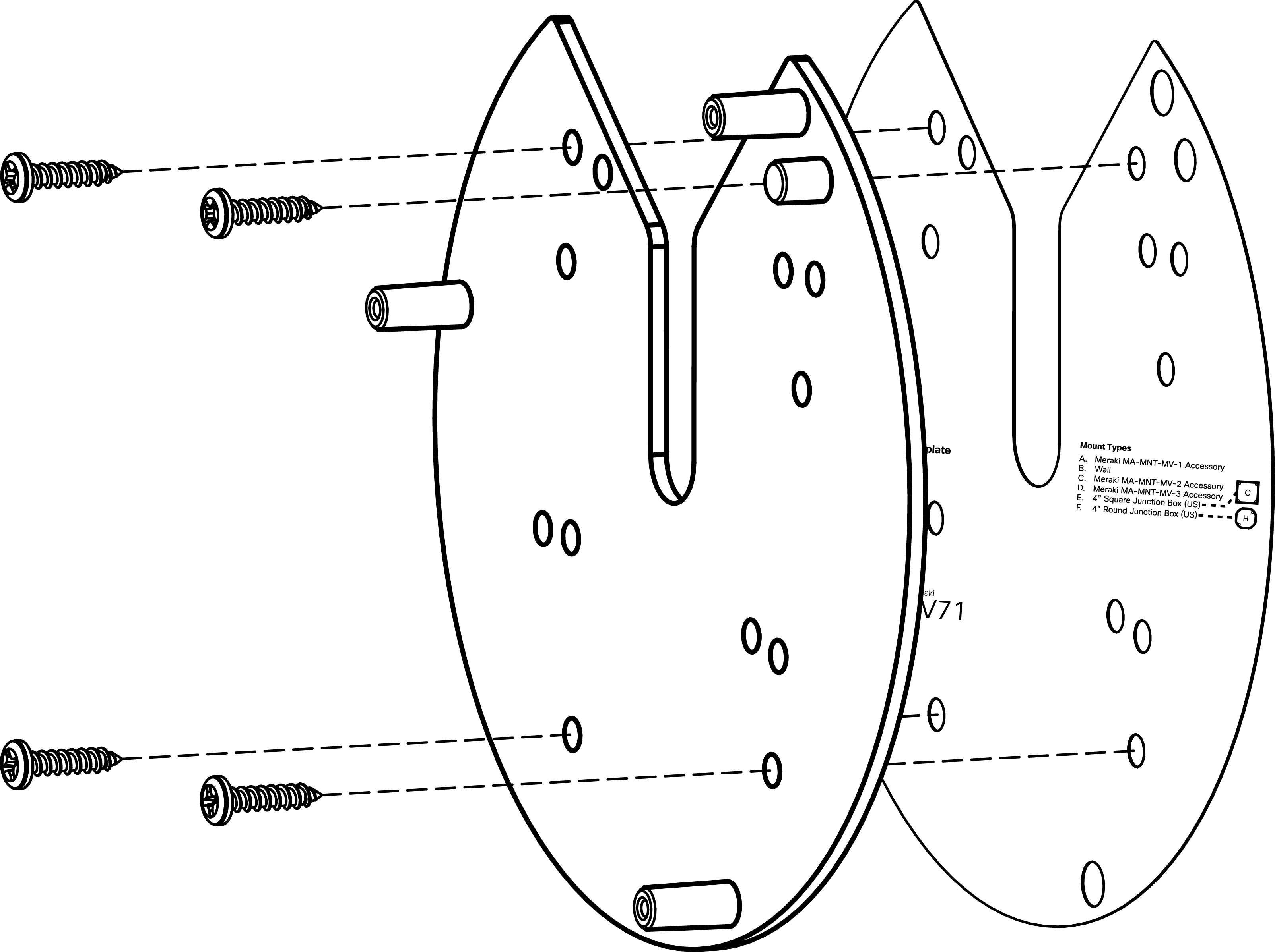
4. Peel the double sided tape backing from the mounting template to stick it on the wall in the desired mounting location. Use template to determine mounting holes before installing the mount plate.
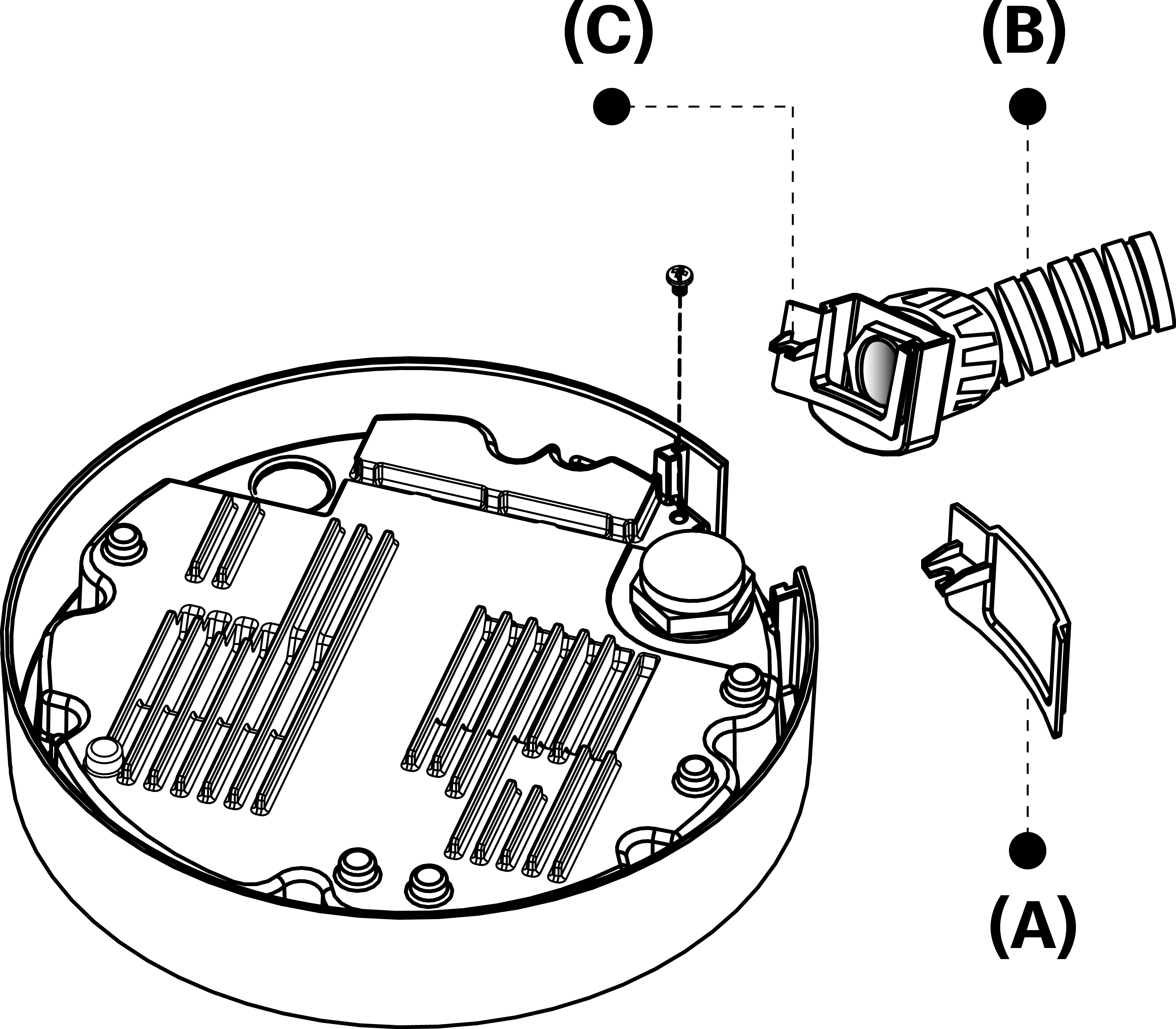
5. If using the side cable exit, remove side outlet cover (A) by unscrewing phillips screw. If using conduit (B), replace side outlet cover with side outlet bushing for conduit adapters (C).
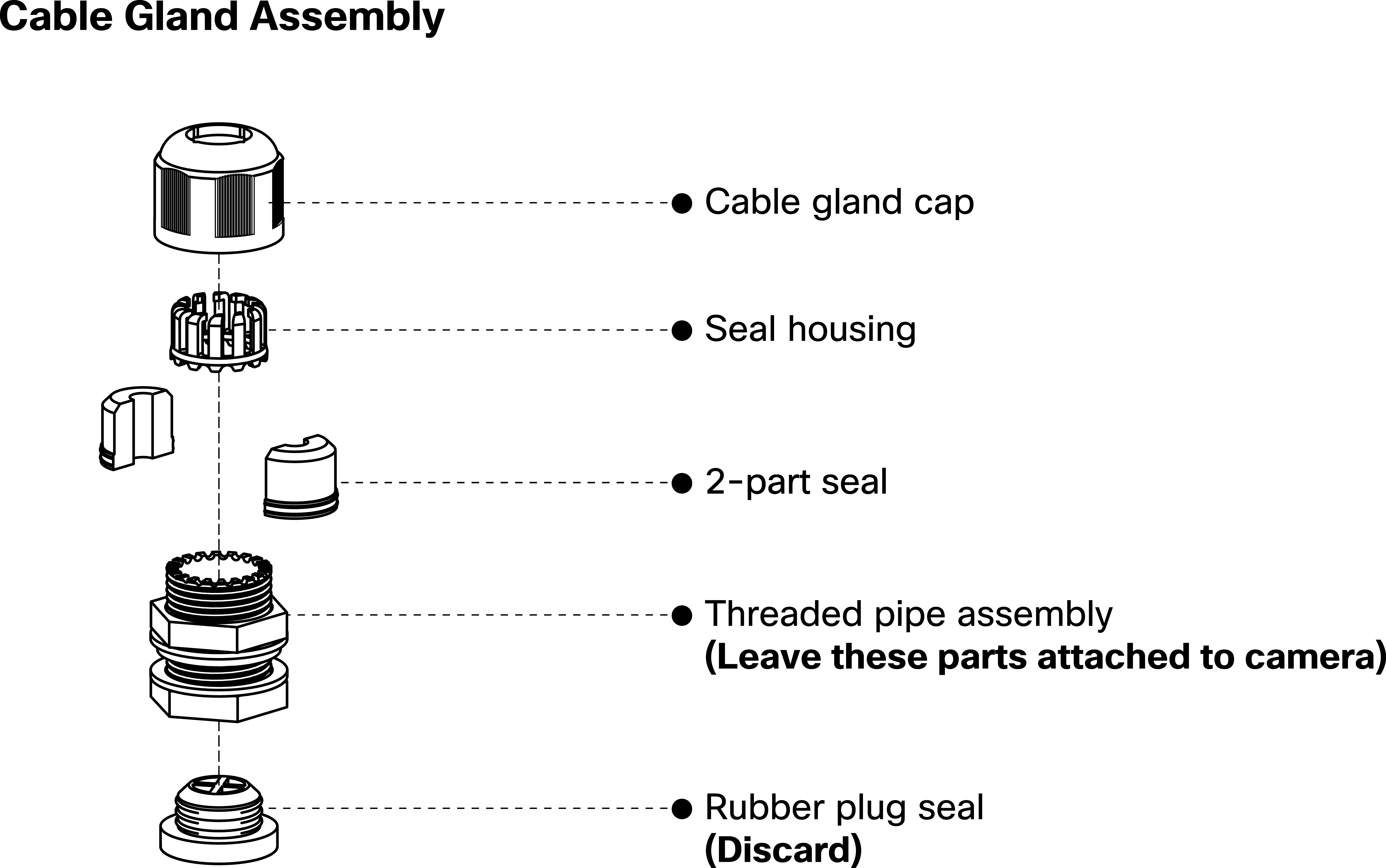
6. Discard the rubber plug seal at the back of the camera. Unscrew the cable gland cap to disassemble the cable gland. Pass a PoE+ RJ45 cable (recommended cable gauge 3.5 ~ 5 mm) through the cable gland components before reassembling to create a moisture proof seal. (See next page for detailed view of cable gland assembly.)
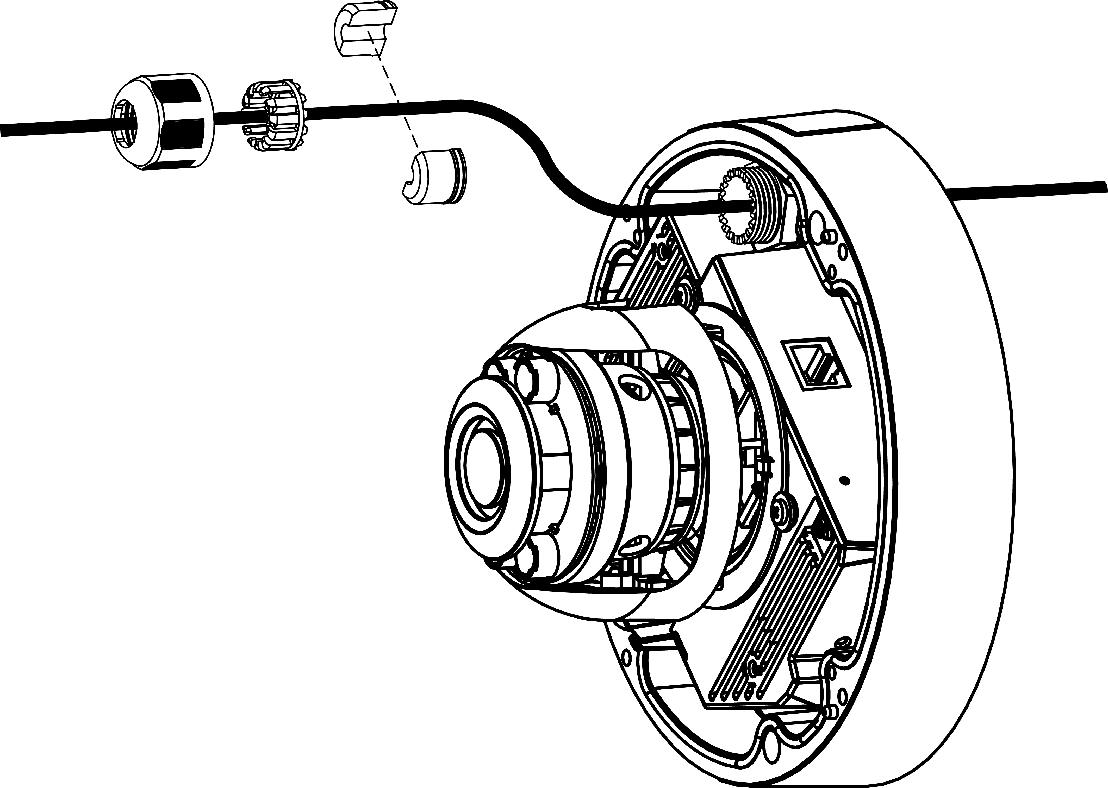
7. Use an RJ45 crimping tool to strip 12mm of the cable sheath and crimp an RJ45 connector onto the cable. Connect the cable to the camera.

Cable should be between 24-26 AWG. Cat6a ethernet cable is not recommended for MV71 deployments.
8. Mount camera onto mounting plate with three pre-installed captive screws.
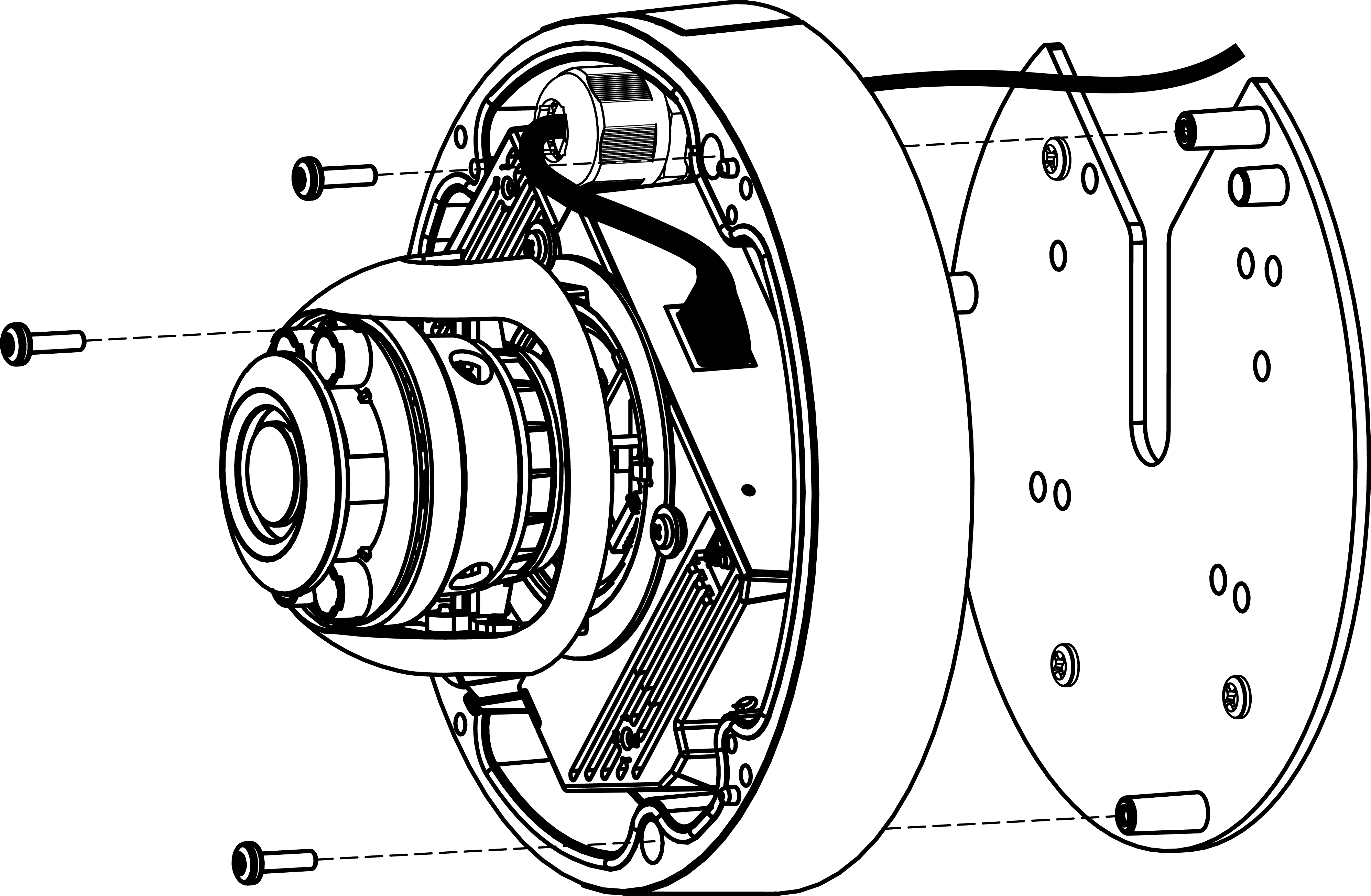
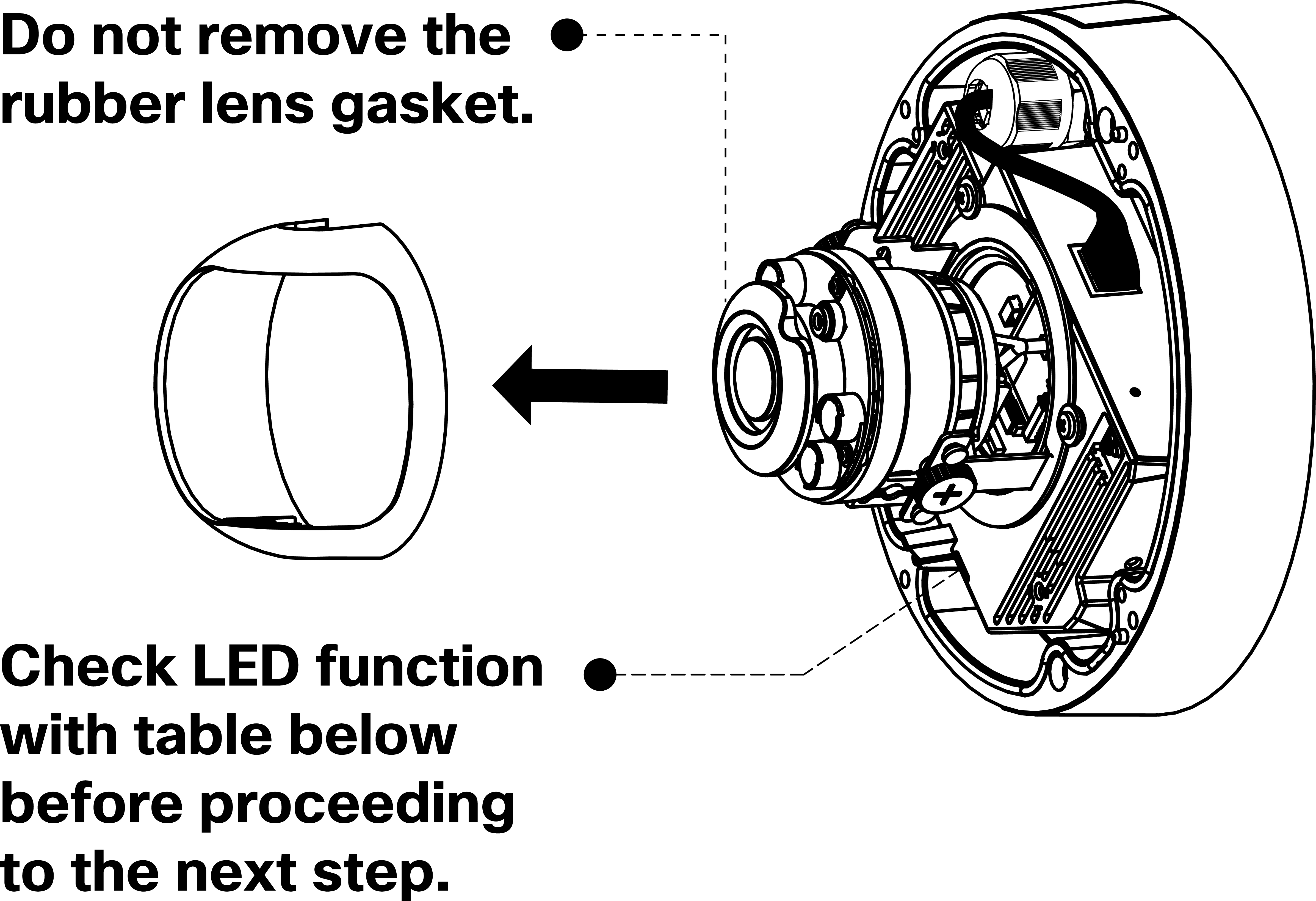
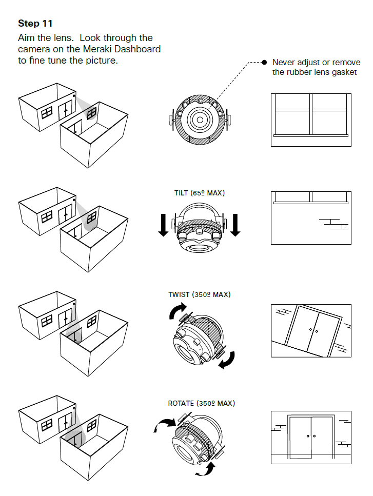
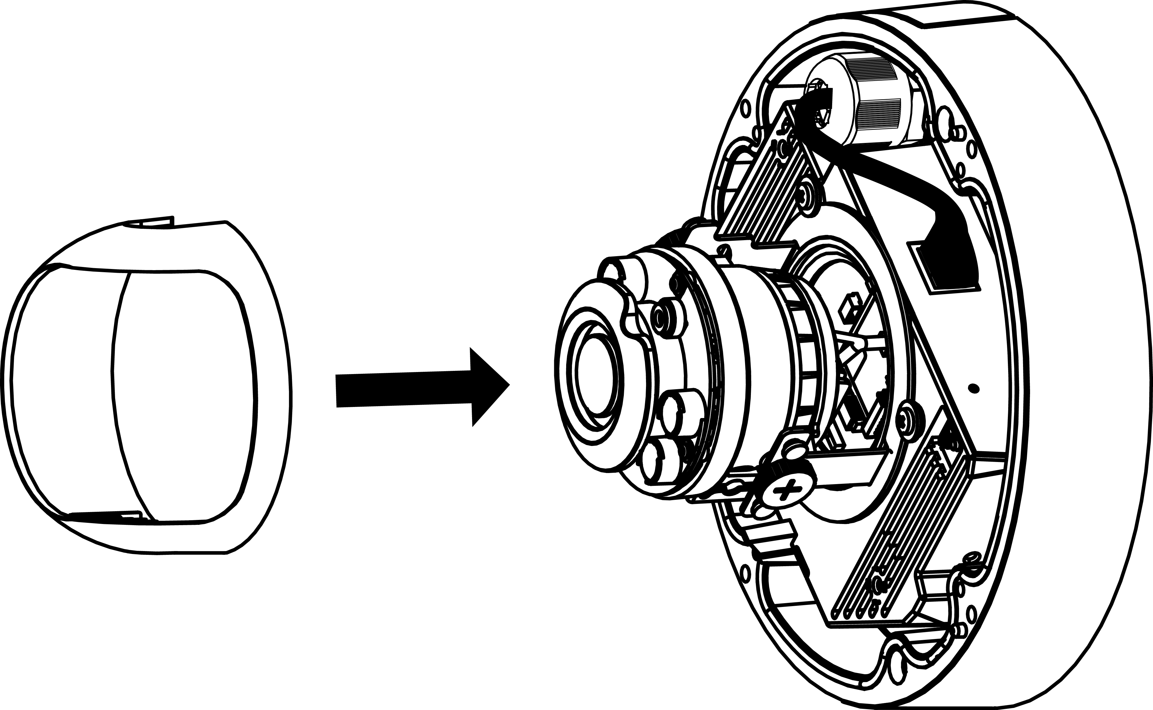
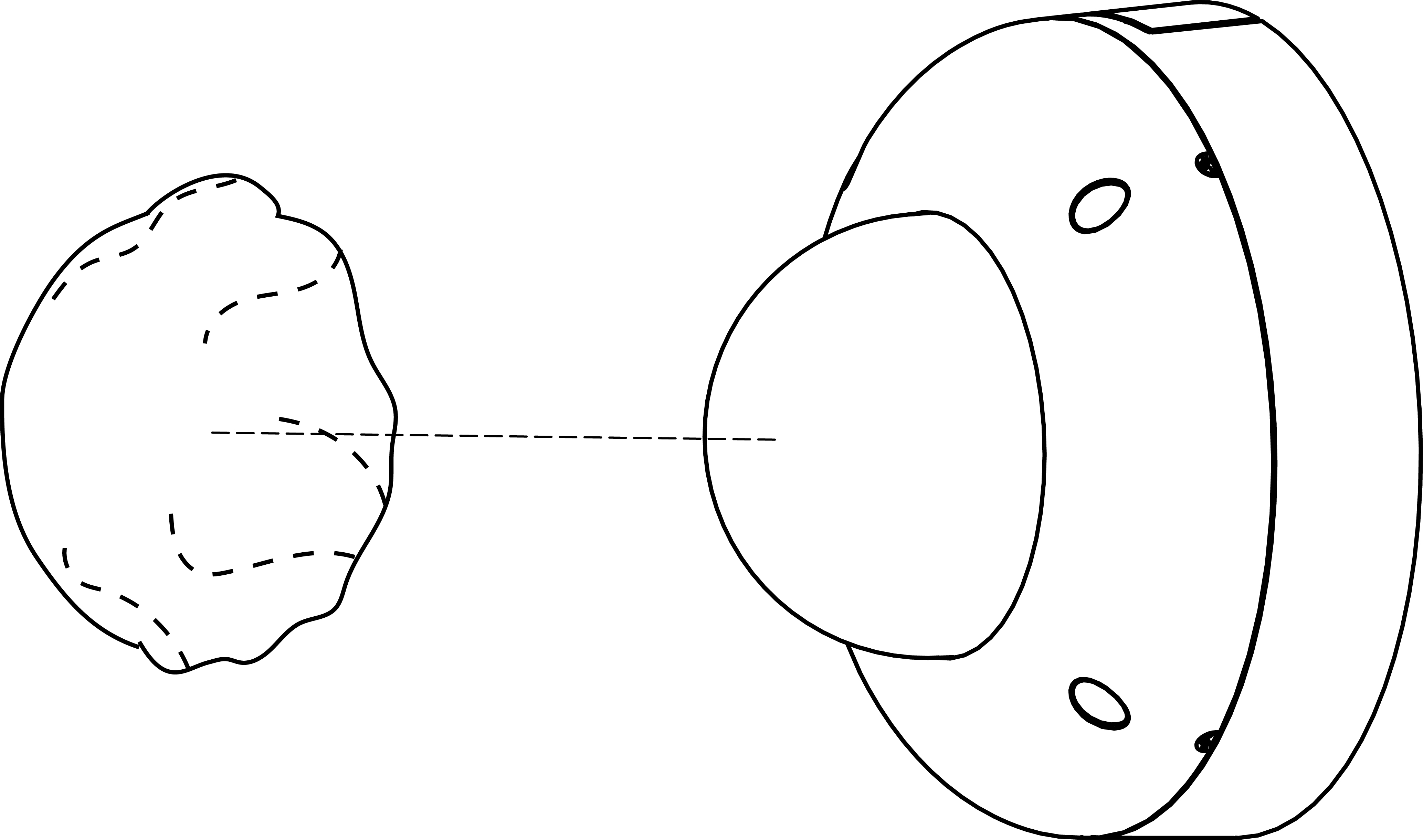
9. Temporarily unsnap the plastic lens guard before adjusting lens angle.
10. Aim the lens and use the Meraki Dashboard to adjust the picture. The camera sensor and lens can tilt up to 65 degrees, rotate up to 350 degrees, and pan up to 350 degrees. The image can be rotated 180 degrees in software, but no other software adjustments are possible. Zoom and focus can be adjusted remotely but cannot be physically adjusted on the camera.
Do not adjust or remove the rubber lens gasket.
11. Replace lens guard by snapping it back down around the lens adjustment thumb screws.
12. Replace dome cover by reattaching it to the dome cover retainer bracket and hinging it closed.
13. Fasten four exterior Torx screws to seal the camera housing. Remove protective plastic sticker from camera bubble.
Powering the MV71
Remove the cable guard on the bottom of the MV71 and route the Ethernet cable from an active port on a 802.3at switch or PoE+ injector.
Power over Ethernet supports a maximum cable length of 300 ft (100 m).
Heating Element
The MV71 is equipped with an internal heating element for low temperature outdoor operations. This allows the working temperature range to be -50°C - 40°C (-58°F - 104°F).
LED Indicator
Your MV71 is equipped with a LED light used to convey information about system functionality and performance:
- Flashing Green (1 second interval) - MV is upgrading or initializing for the first time.
- Flashing Green (3 second interval) - Encrypting disk.
- Solid Green - MV is operating nominally.