
Configuring Site-to-site VPN over MPLS
Many enterprise networks have existing MPLS circuits that connect locations. However if the MPLS goes down, the connection to a remote location is lost. MX Security Appliances can be placed in these networks to dynamically fail over to a VPN connection via a secondary Internet connection. This article describes how the Cisco Meraki Cloud manages the VPN tunnel based on the status of the Internet uplinks, and will illustrate the complete flow of traffic when the VPN is properly enabled and functioning.
General Network Design and Considerations
There are a few high level concepts to mention before getting into the details of network design:
- The MX at the branch location must use the Internet connection of HQ to send its management traffic to the Cloud while the MPLS is in use. With this in mind, the MPLS routers at the branch locations must have a route for Internet bound traffic. For client devices, you can use Flow preferences on the Branch MX to direct Internet bound traffic out the ISP at the branch.
- MXes need to form a VPN over the MPLS connection because unsolicited inbound traffic is dropped. VPN between the two sites resolves this issue.
- If the MPLS fails, the Branch MX will switch to its secondary Internet connection and the MXes will establish a tunnel over VPN.
MPLS Setup in Detail
Diagram of traffic flow when VPN is established over the MPLS Circuit.

Detailing the Flow of VPN Traffic
- Host at Branch location wants to talk to host at HQ.
- SRC IP 172.16.0.10 > DST IP 10.0.5.20.
- Host routes traffic to its default Gateway (Branch MX).
- Branch MX has a VPN tunnel built for that remote Subnet (10.0.5.0/24) thanks to the knowledge of the Cloud.
- Data is encapsulated and sent over the VPN tunnel to the HQ MX in Concentrator Mode.
- MX Concentrator decapsulates the packet and delivers it to its DST IP (10.0.5.20).
- HQ client computer (10.0.5.20) responds to the packet and sends it to its default gateway (HQ Firewall), since it doesn't know about the location of the Branch network.
- HQ Firewall receives the packet and knows that it must route all traffic with a DST network of 172.16.0.0/24 back to the MX Concentrator.
- You need a static route pointing all Remote networks to the MX Concentrator. Example Cisco IOS route statement: ip route 172.16.0.0 255.255.255.0 10.0.5.254.
- The MX concentrator has a tunnel established for the network ID of 172.16.0.0/24, so it encapsulates the traffic and sends it to the Branch MX.
- The Branch MX decapsulates the packet and delivers it to the DST host (172.16.0.10).
- This communication works the same way whether the MXes communicate over the MPLS or over their individual Internet connections.
Cisco Meraki VPN Registry
When the MX devices report to the Dashboard, the Dashboard records both the SRC IP address of the traffic and the Interface IP of the MX. Sometimes these addresses do not match. This is common when the Device is placed in 1-armed VPN Concentrator Mode. This means that the MX has a private IP address, and VPN traffic is forwarded to the hardware for encapsulation.
Below is a screenshot of the Security & SD-WAN > Monitor > Appliance status > Uplink page. Notice that the WAN IP is different from the Public IP address.
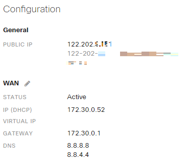
In the diagram above, the Branch MX is routing all traffic over the MPLS to the HQ firewall. The Dashboard bound traffic has the same SRC IP address (230.45.122.56) as the HQ MX Concentrator. However, the IP addresses of the Interfaces (10.0.5.254 and 192.168.1.2) are both local to their network, and those addresses are reported to the Dashboard as well.
Below is an example of VPN Registry and the IP addresses that the Cloud records.

In this example, the Dashboard knows that the two devices can’t form a VPN Tunnel through the same SRC IP address, so it will try the IP addresses of the Interfaces. The routing through the MPLS allows the MX devices to communicate using these Private IP addresses, and the tunnel is dynamically established.
Failover to Secondary ISP when MPLS Circuit is Not Available
If the MPLS goes down, the Branch MX will know that it lost connection to the Cloud and will fail over to its backup ISP connection. Once the MX is communicating with the Cloud again, the registry entry is updated.

Below is an example of the VPN Registry now that the Branch is communicating to the Cloud from a different public IP address.

The MX Concentrator will now establish the VPN to the Public IP address of the Branch MX.
Flow Preferences
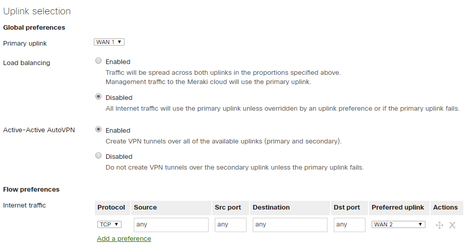
Some users prefer to send Internet bound traffic out the secondary Internet connection at the branch location. You can add Flow Preferences under Security & SD-WAN > Configure > SD-WAN & traffic shaping. The MX will route the traffic according the most specific route. Since the VPN routes are more specific than the route of 0.0.0.0/0, the VPN traffic will go out the VPN Interface.
Below is a screenshot of Flow preferences that facilitate the desired traffic flow:
MX Site-to-site VPN allows remote sites to dynamically fail over to back up Internet Connections when an MPLS connection becomes unavailable. This can happen automatically since the MX harnesses the information that the Cloud knows about the devices.
Additional Resources
For a configuration that allows an existing MPLS link to fail-over to a site-to-site VPN connection, please refer to our documentation on MPLS failover to site-to-site VPN.