

C8111-C-G2-MX, C8121-W-G2-MX, and C8121-CW-G2-MX Installation Guide
The document offers a detailed hardware installation guide for the Cisco Secure Router C8111-C-G2, C8121-W-G2 and C8121-CW-G2, covering mounting options, port connections, and LED indicators, facilitating a straightforward setup process for deploying secure and reliable remote work solutions.
About this Guide
This guide provides instructions on how to install and configure your C8111-C-G2, C8121-W-G2, and C8121-CW-G2 device. This guide also provides mounting instructions and limited troubleshooting procedures. For more MX-series device installation guides, refer to the MX-series installation guides section on our documentation website.
Product Overview
The Cisco Secure Router C8111-C-G2, C8121-W-G2, and C8121-CW-G2 are enterprise security appliances running MX OS which are designed for distributed deployments requiring remote administration across small to medium branch environments. It is ideal for network administrators who demand both ease of deployment and a state-of-the-art feature set.
The Cisco Secure Router C8121-W-G2 and C8121-CW-G2 offer Wi-Fi 6, 10 LAN Gigabit Ethernet ports, 2x 2.5 mGig WAN Ethernet ports, including a built-in PoE-enabled WAN port for powering an MG or other powered devices, as well as 3 PoE-enabled LAN ports. The Cisco Secure Router C8111-C-G2 and C8121-CW-G2 offer 5G cellular modems offering up to 10 LAN Gigabit ethernet ports, 2x 2.5 mGig WAN Ethernet ports, including a bult-in PoE-enabled WAN port for powering an MG or other devices, as well as up to 3 PoE-enabled LAN ports.
Each model is designed to securely extend the power of Meraki cloud managed networking to almost any location. The C8111-C-G2, C8121-W-G2 and C8121-CW-G2 simplify any deployment that requires a diverse set of ways to provide device connectivity.

Features
|
|
Context and Comparisons
|
|
C8111-C-G2 |
C8121-W-G2 |
C8121-CW-G2 |
|
Max Stateful Firewall Throughput in NAT mode |
2 Gbps |
2 Gbps |
2 Gbps |
|
Max VPN Throughput |
1200 Mbps |
1200 Mbps |
1200 Mbps |
|
Backup Cellular Uplink |
Built-in 5G SA & CAT20 LTE Modem with 4 x External Antennas |
N/A |
Built-in 5G SA & CAT20 LTE Modem with 4 x External Antennas |
|
PoE Capabilities |
Yes, 2.5 x MGig RJ45 WAN Ports (802.3at) 1x GbE RJ45 LAN Ports (802.3bt, 45W) |
Yes, 2.5 x MGig RJ45 WAN Ports (802.3at) 3x GbE RJ45 LAN Ports (802.3bt, 45W) |
Yes, 2.5 x MGig RJ45 WAN Ports (802.3at) 3x GbE RJ45 LAN Ports (802.3bt, 45W) |
|
Wi-Fi |
N/A |
Dual-band 2x2 WiFi 6 |
Dual-band 2x2 WiFi 6 |
|
Recommended LAN Clients |
Up to 200 devices |
Up to 200 devices |
Up to 200 devices |
Physical Specifications
|
|
C8111-C-G2 |
C8121-W-G2 |
C8121-CW-G2 |
|
RJ45 WAN Interfaces |
2x Dedicated MGigE RJ45 |
2x Dedicated MGigE RJ45 |
2x Dedicated MGigE RJ45 |
|
Cellular WAN Interfaces |
Built-in Cellular Uplink |
N/A |
Built-in Cellular Uplink |
|
LAN Interfaces - Dedicated |
4 x Dedicated GbE RJ45 |
10 x Dedicated GbE RJ45 |
10 x Dedicated GbE RJ45 |
|
Wireless Radio Information |
N/A |
Wi-Fi 6 2x2 MU-MIMO |
Wi-Fi 6 2x2 MU-MIMO |
|
Antennas |
4x External LTE Antennas |
2 x 2 MU-MIMO with two spatial streams |
2 x 2 MU-MIMO with two spatial streams 4x External Cellular Antennas |
|
Maximum Wireless Data Rate |
1.5 Gbps* |
|
1.5 Gbps* |
|
Mount Type |
Desktop / Wall Mount |
Desktop / Wall Mount |
Desktop / Wall Mount |
|
Dimensions (h x d x w) |
1.3 x 6.9 x 12.4 in / 34 x 176 x 316 mm |
1.3 x 8 x 13.7 in / 34 x 203 x 348 mm |
1.3 x 8 x 13.7 in / 34 x 203 x 348 mm |
|
Weight |
3.2 lbs / 1.451 kg |
3.7 lbs / 1.696 kg |
3.9 lbs / 1.783 kg |
|
Power Supply |
150W (54 V / 0.92 A) |
250W (54 V / 0.92 A) |
250W (54 V / 0.92 A) |
|
System Power (idle/max) |
( 39W / 45W ) |
( 56W / 64W ) |
( 68W / 87W ) |
|
System + PoE Power Load (idle/ max) |
( 39W / 126W ) |
( 56W / 221W ) |
( 68W / 233W ) |
|
Operating Temperature |
32°F - 113 °F 0°C - 45°C |
32°F - 113 °F 0°C - 45°C |
32°F - 113 °F 0°C - 45°C |
|
Storage and Transportation Temperature |
-4°F - 158°F -20°C - 70°C |
-4°F - 158°F -20°C - 70° C |
-4°F - 158°F -20°C - 70° C |
|
Humidity |
5% to 95% |
5% to 95% |
5% to 95% |
* Refers to maximum over-the-air data frame rate capability of the radio chipset, and may exceed data rates allowed by IEEE 802.11ax operation.
Cellular Interface
|
|
Cellular Bands |
|
5G |
n1, n2, n3, n5, n7, n8, n12, n13, n14, n18, n20, n25, n26, n28, n29, n30, n38, n40, n41, n48, n66, n70, n71, n75, n76, n77, n78, n79 |
|
LTE |
B1, B2, B3, B4, B5, B7, B8, B12, B13, B14, B18, B19, B20, B21, B25, B26, B28, B29, B30, B32, B34, B38, B39, B40, B41, B42, B43, B46, B48, B66, B71 |
|
Certified Certifications |
PTCRB (US), GCF(EU), IC (CA), FCC (US) |
|
Certification |
AT&T, T-Mobile |
|
Tested Carriers |
Verizon, AT&T, T-Mobile, Telia, TDC, Vodafone |
Carrier compatibility is generally based on having compatible bands on the modem. In the open market, carriers may only require regulatory domain certifications and open market certifications, like the PTCRB and GCF, to be compatible for their network. Sometimes carriers will require additional testing before a device can be used on their network. The Tested Carriers section is based on Meraki device certifications being approved by those specific carriers. A carrier being listed above means that they have officially certified the Meraki product for their cellular network. There may be many unlisted carriers that could be functionally compatible with Meraki devices. The list of tested certified carriers is based on the carrier validating Meraki per their network parameter requirements. If a carrier you are looking to use is not listed above, it could be that they do not require additional compliance testing for their network.
Accessories
|
Accessory |
Description |
|
MA-PWR-150WAC |
C8111-G2-MX Replacement Power Adapter (C8111-C-G2) (150 Watts AC) |
|
MA-PWR-250WAC |
C8121-G2-MX Replacement Power Adapter (C8121-W-G2 and C8121-CW-G2) (250 Watts AC) |
|
MA-PWR-CORD-US |
1x AC Power Cable, US plug |
|
MA-PWR-CORD-EU |
1x AC Power Cable, EU plug |
|
MA-PWR-CORD-UK |
1x AC Power Cable, UK plug |
|
MA-PWR-CORD-AU |
1x AC Power Cable, AU plug |
|
MA-WMNTBR-PWR-ADP |
1x Power adapter holder for external power adapter |
|
5G-ANT-C8111 |
Includes 4x cellular antennas for the C8111-C-G2 |
|
5G-ANT-C8121 |
Includes 4x cellular antennas for the C8121-CW-G2 |
Product View and Physical Features
Package Contents

In addition to the C8111-C-G2, C8121-W-G2, and C8121-CW-G2 device, the following are provided:
|
C8111-C-G2 |
C8121-W-G2 |
C8121-CW-G2 |
|
Power Adapter (No Power Cable) |
Power Adapter (No Power Cable) |
Power Adapter (No Power Cable) |
|
4x Cellular Antennas |
|
4x Cellular Antennas |
Front Panel
C8111-C-G2, C8121-W-G2 and C8121-CW-G2

Device Status Indicator
The C8111-C-G2, C8121-W-G2 and C8121-CW-G2 use a single LED to inform the user of the device's status.
|
LED Status |
Meaning |
|
Solid orange |
Power is applied but the appliance is not connected to the Meraki Dashboard |
|
Rainbow Colors |
The appliance is attempting to connect to Meraki Dashboard |
|
Flashing White |
Firmware upgrade in progress |
|
Solid White |
Fully operational/connected, uplink actively using wired WAN |
|
Solid Purple |
Fully operational/connected, uplink actively using cellular |
Cellular Status Indicator
The C8111-C-G2 and C8121-CW-G2 use a single LED to report the signal strength of the primary cellular band for the current cellular connection.

|
LED Status |
Meaning |
|
Solid orange (upon boot) |
Power is applied |
|
Off |
After boot, if no SIM card is detected by the device then the cellular status light will be off for 10 seconds, before failing over to the eSIM. |
|
Rainbow Colors |
The appliance has detected a SIM card and is attempting to connect to a cellular network. The colors used are: Red, Orange, Yellow, Lime Green, and Green |
|
Solid Red |
Device is connected to the cellular provider with “Poor” RSRP |
|
Solid Orange (after boot) |
Device is connected to the cellular provider with “Okay” RSRP |
|
Solid Yellow |
Device is connected to the cellular provider with “Good” RSRP |
|
Solid Lime Green |
Device is connected to the cellular provider with “Great” RSRP |
|
Solid Green |
Device is connected to the cellular provider with “Excellent” RSRP |
Back Panel
C8111-C-G2
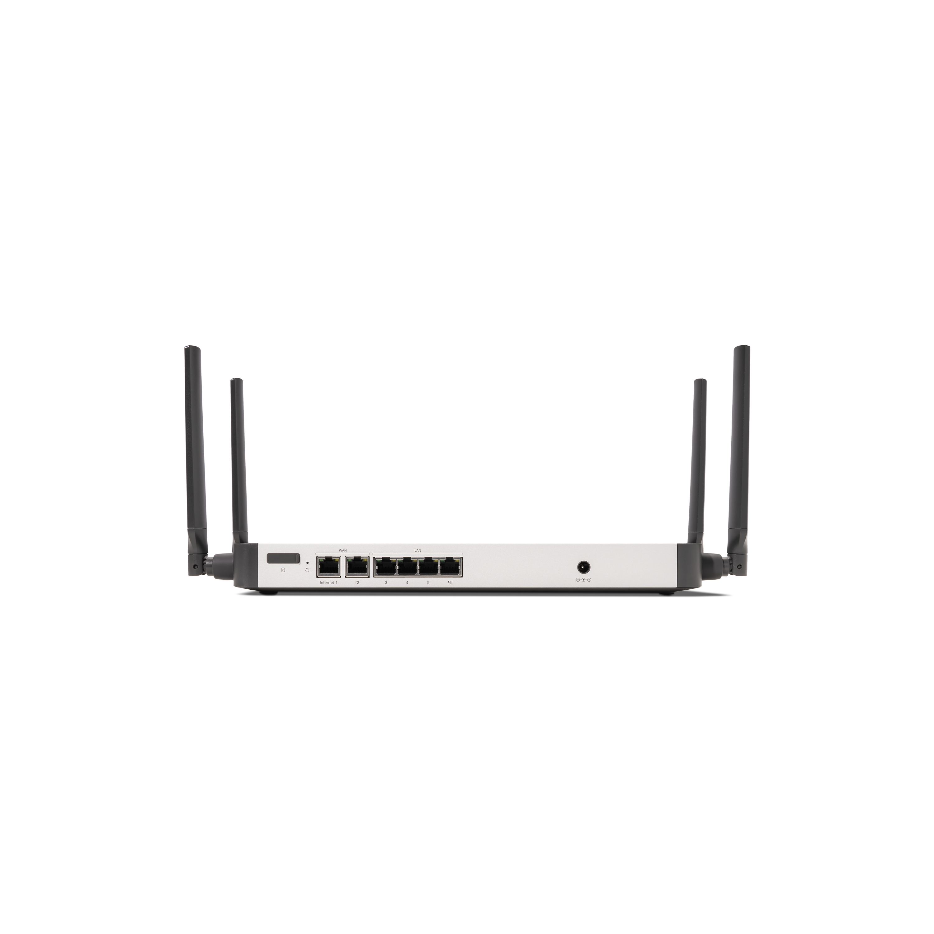
Additional functions on the back panel are described below, from left to right.
|
SIM Card Slot |
Active and supported SIM cards can be inserted into this slot to enable cellular capabilities. The SIM card must be interested with the contact pads facing upwards when the device is sitting on its feet |
|
Reset button |
Insert a paper clip if a reset is required.
|
|
WAN / Internet port |
[Far left two Ethernet port] This port provides connectivity to the WAN. [Second port from the Far-left Ethernet port] This port provides PoE+ for connectivity to cellular gateways or other PoE powered upstream devices. A steady green LED indicates bidirectional connectivity, and flashing green indicates traffic. |
|
LAN ports |
These 4 ports provide connectivity to computers, printers, access points, or Ethernet switches. A steady green LED indicates bidirectional connectivity, and flashing green indicates traffic. |
|
PoE+ Port |
[Far right Ethernet port] One of the LAN port provides UPoE for connectivity to computers, printers, access points, or Ethernet switches, up to 45W of PoE power. A steady green LED indicates bidirectional connectivity, and flashing green indicates traffic. |
|
Power input |
Designed for use only with the unit’s power supply. |
C8121-W-G2
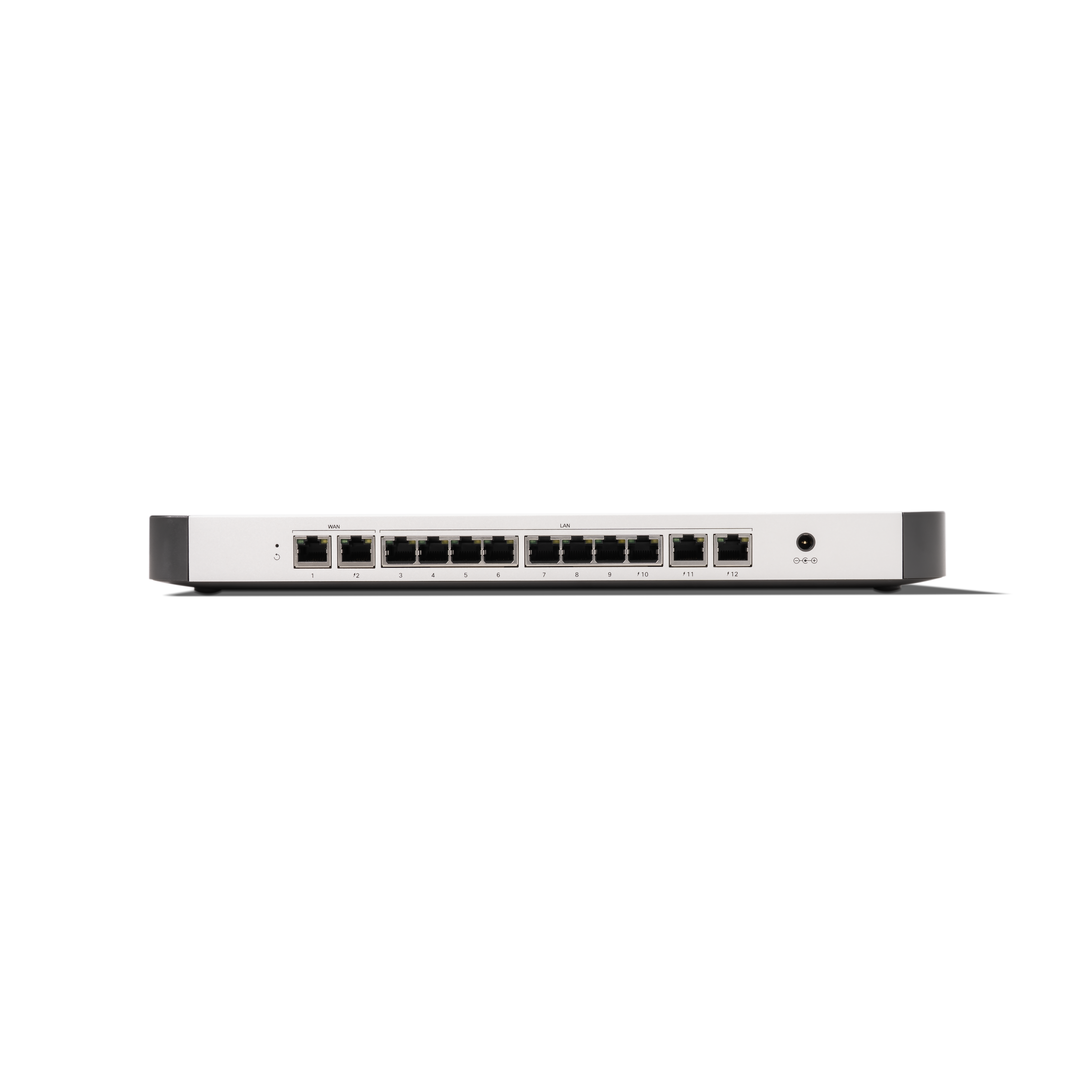
Additional functions on the back panel are described below, from left to right.
|
Reset button |
Insert a paper clip if a reset is required.
|
|
WAN / Internet port |
[Far left two Ethernet ports] This port provides connectivity to the WAN. [Second port from the Far-left Ethernet port] This port provides PoE+ for connectivity to cellular gateways or other PoE powered upstream devices that require up to 30W of PoE power. |
|
LAN ports |
These 4 ports provide connectivity to computers, printers, access points, or Ethernet switches. A steady green LED indicates bidirectional connectivity, and flashing green indicates traffic. |
|
PoE+ Port |
[Far right three Ethernet ports] Three of the LAN ports provides UPoE for connectivity to computers, printers, access points, or Ethernet switches, up to 45W of PoE power. |
|
Power input |
Designed for use only with the unit’s power supply. |
C8121-CW-G2

Additional functions on the back panel are described below, from left to right.
|
SIM Card Slot |
Active and supported SIM cards can be inserted into this slot to enable cellular capabilities. The SIM card must be interested with the contact pads facing upwards when the device is sitting on its feet |
|
Reset button |
Insert a paper clip if a reset is required.
|
|
WAN / Internet port |
[Far left two Ethernet ports] This port provides connectivity to the WAN. [Second port from the Far-left Ethernet port] This port provides PoE+ for connectivity to cellular gateways or other PoE powered upstream devices that require up to 30W of PoE power. |
|
LAN ports |
These 4 ports provide connectivity to computers, printers, access points, or Ethernet switches. A steady green LED indicates bidirectional connectivity, and flashing green indicates traffic. |
|
PoE+ Port |
[Far right three Ethernet ports] Three of the LAN ports provides UPoE for connectivity to computers, printers, access points, or Ethernet switches, up to 45W of PoE power. |
|
Power input |
Designed for use only with the unit’s power supply. |
Bottom Panel
C8111-C-G2-MX, C8121-W-G2, and C8121-CW-G2
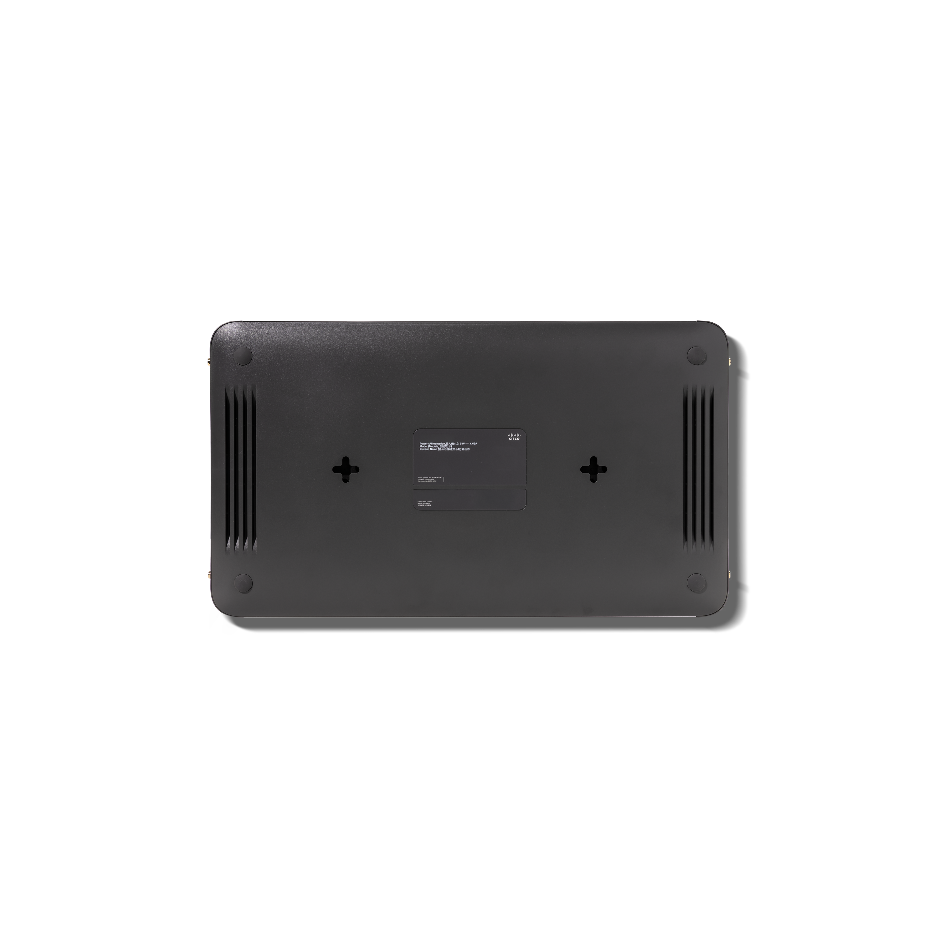
Please note that the serial number is located on the product label on the bottom panel of the C8111-C-G2, C8121-W-G2 and C8121-CW-G2.
Pre-install Preparation
You should complete the following steps before going on-site to perform an installation.
Configure your Dashboard Network
The following is a brief overview only of the steps required to add an C8111-C-G2, C8121-W-G2 and C8121-CW-G2 to your network. For detailed instructions about creating, configuring and managing Meraki networks, refer to our Managing Dashboard Networks document. Additional resources can also be found via: documentation.meraki.com.
-
Login to http://dashboard.meraki.com. If this is your first time, create a new account.
-
Find the network to which you plan to add your C8111-C-G2, C8121-W-G2, and C8121-CW-G2 or create a new network.
-
Add your C8111-C-G2, C8121-W-G2, and C8121-CW-G2 to your network. You will need your Meraki order number (found on your invoice) or the serial number of each C8111-C-G2, C8121-W-G2, and C8121-CW-G2, which looks like Qxxx-xxxx-xxxx, and is found on the bottom of the unit. You will also need your Enterprise license key, which you should have received via email.
-
Go to the map / floor plan view and place each C8111-C-G2, C8121-W-G2, and C8121-CW-G2 on the map by clicking and dragging it to the location where you plan to mount it.
Check and Set Firmware
To ensure your C8111-C-G2, C8121-W-G2, and C8121-CW-G2 performs optimally immediately following installation, it is recommended that you facilitate a firmware upgrade prior to mounting your C8111-C-G2, C8121-W-G2, and C8121-CW-G2.
-
Attach your C8111-C-G2, C8121-W-G2, and C8121-CW-G2 to power and a wired Internet connection.
-
The C8111-C-G2, C8121-W-G2, and C8121-CW-G2 will turn on and the power LED will glow solid orange.
-
If the unit requires an upgrade, the power LED will begin blinking white until the upgrade is complete, at which point the LED will turn solid white. You should allow at least a few minutes for the firmware upgrade to complete, depending on the speed of your internet connection.
Check and Configure Upstream Firewall Settings
If an upstream firewall is already in place, it must allow outgoing connections to a particular set of IP addresses and ports. The most current list of outbound ports and IP addresses for your organization can be found on the firewall configuration page in your dashboard.
Installation Instructions
Mounting Hardware
Wall screws and anchors will allow you to mount the gateway on a drywall surface, either vertically or horizontally. The distance between the holes you drill should be 5-1/8 inches (13 cm).
-
For mounting on drywall, use a ¼-in drill bit, then insert the plastic drywall anchor and screw assemblies.
-
For mounting on wood or a similar surface, use only the screws.
-
Allow the heads of the screws to stick out far enough to be inserted securely into the back of the appliance.
Connecting to WAN
All C8111-C-G2, C8121-W-G2, and C8121-CW-G2 devices must have an IP address. This section describes how to configure your local area network before you deploy it. A local management web service, running on the appliance, is accessed through a browser running on a client PC. This web service is used for configuring and monitoring basic ISP/WAN connectivity.
Setting up a Static IP Address
Do the following to configure basic connectivity and other networking parameters:
-
Using a client machine such as a laptop, connect to one of the LAN ports of the C8111-C-G2, C8121-W-G2, and C8121-CW-G2.
-
Using a browser on the client machine, access the appliance's built-in web service by browsing to http://setup.meraki.com. (You do not have to be connected to the Internet to reach this address)
-
Click Uplink configuration under the Local status tab. The default credentials use the device serial number as the username, with a blank password field.
-
Choose Static for the IP Assignment option.
-
Enter the IP address, subnet mask, default gateway IP and DNS server information.
Setting up a DHCP IP Address
By default, all C8111-C-G2, C8121-W-G2, and C8121-CW-G2 devices are configured to DHCP from upstream WAN / ISP servers. Simply plug the C8111-C-G2, C8121-W-G2. and C8121-CW-G2's WAN / Internet port to your upstream circuit and wait a few minutes for the unit to negotiate a DHCP address.
When the WAN connection is fully enabled, Internet LED 1 will turn green.
Setting up Cellular Failover
The C8111-C-G2 and C8121-CW-G2 has an embedded 5G module for cellular failover connections. The following section will walk through first-time set-up of an C8111-C-G2 and C8121-CW-G2 with an internet connection as a primary connection and cellular as failover.
To set up the cellular failover connection, follow the steps below:
-
Power off the C8111-C-G2 or C8121-CW-G2. Swapping/installing SIM cards while the C8111-C-G2 or C8121-CW-G2 is powered on may cause unexpected behavior or error.
-
Uncover the SIM slot cover.
-
Insert a nano SIM card (4FF size) until it ‘clicks’
-
Cover the SIM slot cover again
-
Power on the C8111-C-G2 or C8121-CW-G2 and wait for the C8111-C-G2 or C8121-CW-G2 to show as online in the Meraki dashboard
-
Check with the carrier of choice if an APN needs to be configured. If so, do that from the Meraki Dashboard under Teleworker Gateway > Monitor > Appliance Status > Uplink tab
-
Navigate to Teleworker Gateway > Monitor > Appliance Status > Uplink tab and next to Status, select the edit (pencil) button and then select Enabled. When the cellular uplink is successfully connected, you will be able to see the status on the left hand side of the Appliance Status page and in the Uplink tab. The connection will say Ready when it is successfully connected
-
Test the cellular failover connection by unplugging the wired connection or by using the traceroute tool under Teleworker Gateway > Monitor > Appliance Status in the Tools tab
-
If, after following the steps above, the SIM card is not detected, please confirm with your carrier that the SIM card is active and has data. You will need the ICCID of the SIM card and IMEI of the device to get troubleshooting help from the carrier
-
Please contact the Meraki Support team if the cellular connection is still not being recognized after following the steps above.
Inserting a Physical SIM Card While Cellular is Connected via eSIM
By default, Auto Failover is disabled. The C8111-C-G2 and C8121-CW-G2 support hot swapping from eSIM to the physical SIM card.
A Physical SIM Card is Inserted into the Device While it is Connected Via the eSIM Bootstrap Profile
Regardless of how long the device has been powered on, when a physical SIM card is inserted into the device and is using the eSIM bootstrap profile. The device would immediately move from the eSIM to the physical SIM card.
A Physical SIM Card is Inserted into the Device When the Device is Connected Via eSIM With a Target Profile
Regardless of how long the device has been powered on, the device would continue to operate with the eSIM and the target profile when a physical SIM card is inserted into the device and the device is using the eSIM with the bootstrap profile.
The C8111-C-G2 or C8121-CW-G2 will not attempt to move over to the physical SIM card unless this is manually changed via the device’s local status page or via the Meraki Dashboard to change the active SIM card.
The Physical SIM Card is Removed from the Device While Being Used
If the physical SIM card is removed from the device, then the device will attempt to connect via the eSIM via the bootstrap or target profile.
The Device is Attached to the Cellular Network with the eSIM’s Target Profile, but is Unable to Pass its Health Check and then a Physical SIM Card Physically Inserted into the Device
The device will continue to use the eSIM on the target profile and will not attempt to move over to the physical SIM card.
Additional Settings
Please note that all these settings below are accessible only via the local management console.
Setting VLANs
If your WAN uplink is on a trunk port, choose VLAN tagging > Use VLAN tagging and enter the appropriate value for VLAN ID for your network.
Setting PPPoE
PPPoE authentication may be required if you are connecting a C8111-C-G2, C8121-W-G2, and C8121-CW-G2 device to a DSL circuit. You need to know your authentication option and credentials (supplied by your ISP) in order to complete these steps.
-
Choose Connection Type > PPPoE.
-
Select your Authentication option.
-
If you select Use authentication, enter appropriate values for Username and Password.
Web Proxy Settings
These settings take effect if the C8111-C-G2, C8121-W-G2, and C8121-CW-G2 device has to fall back to using HTTP to contact the Cloud Controller. By default, web proxy is disabled. To enable web proxy, do the following:
-
Choose Web proxy > Yes.
-
Enter values as appropriate for Hostname or IP and Port.
-
If you require authentication, choose Authentication > Use authentication, and enter appropriate values for Username and Password.
To apply all configuration settings to the appliance, be sure to click Save Settings at the bottom of the page.
Configuring Physical Link Settings
To configure physical link settings on the Ethernet ports, click Local status > Ethernet configuration. You can enable half-duplex, full-duplex, and autonegotiation, as well as set 10- or 100-Mbps data rates.
Basic Troubleshooting
The following steps can be used for troubleshooting basic connectivity issues with your C8111-C-G2, C8121-W-G2, and C8121-CW-G2.
-
Reset the C8111-C-G2, C8121-W-G2, and C8121-CW-G2
-
Factory reset the C8111-C-G2, C8121-W-G2 and C8121-CW-G2 by holding the factory reset button for 5 seconds
-
Try switching cables, or testing your cable on another device
Reference https://documentation.meraki.com/ for additional information and troubleshooting tips.
If you are still experiencing hardware issues, please contact Cisco Meraki support by logging in to dashboard and using the Help option near the top of the page, then opening and email case or calling using the contact information on that page.
Warranty
Cisco Secure Router 8000 Series warranty coverage periods are as follows:
|
Product |
Warranty Period |
Warranty Information |
|
C8111-C-G2, C8121-W-G2, and 8121-CW-G2
|
2 Years |
|
|
C8111-C-G2, C8121-W-G2, and C8121-CW-G2 Accessories |
1 Year |
The following are considered accessories: SFP Modules, all mounting kits and stands, interface modules, additional power cords |
Additional warranty information can be found on the Return Policy and Requesting a RMA page of the Cisco website.
If your Cisco Meraki device fails and the problem cannot be resolved by troubleshooting, contact support to address the issue. Once support determines that the device is in a failed state, they can process an RMA and send out a replacement device free of charge. In most circumstances, the RMA will include a pre-paid shipping label so the faulty equipment can be returned.
In order to initiate a hardware replacement for non-functioning hardware that is under warranty, you must have access to the original packaging the hardware was shipped in. The original hardware packaging includes device serial number and order information, and may be required for return shipping.
Cisco Secure Routers C8111-C-G2, C8121-W-G2, and C8121-CW-G2 devices have been tested and found to comply with the limits for a Class B digital device, pursuant to part 15 of the FCC rules. These limits are designed to provide reasonable protection against harmful interference in a residential installation. This equipment generates, uses and can radiate radio frequency energy and, if not installed and used in accordance with the instructions, may cause harmful interference to radio communications. However, there is no guarantee that interference will not occur in a particular installation.
Support and Additional Information
If issues are encountered with device installation or additional help is required, contact Meraki Support by logging in to dashboard.meraki.com and opening a case by visiting the Get Help section.
-
The equipment is intended for industrial or other commercial activities.
-
The equipment is used in areas without exposure to harmful and dangerous production factors, unless otherwise specified in the operational documentation and/or on the equipment labeling.
-
The equipment is not for domestic use. The equipment is intended for operation without the constant presence of maintenance personnel.
-
The equipment is subject to installation and maintenance by specialists with the appropriate qualifications, sufficient specialized knowledge, and skills.
-
Rules and conditions for the sale of equipment are determined by the terms of contracts concluded by Cisco or authorized Cisco partners with equipment buyers.
-
Disposal of a technical device at the end of its service life should be carried out in accordance with the requirements of all state regulations and laws.
-
Do not throw in the device with household waste. The technical equipment is subject to storage and disposal in accordance with the organization's disposal procedure.
-
The equipment should be stored in its original packaging in a room protected from atmospheric precipitation. The permissible temperature and humidity ranges during storage are specified in the Operation (Installation) Manual.
-
Transportation of equipment should be carried out in the original packaging in covered vehicles by any means of transport. The temperature and humidity during transportation must comply with the permissible established ranges of temperature and humidity during storage (in the off state) specified in the Operation Manual (Installation).
For additional information on Meraki hardware and for other installation guides, please refer to documentation.meraki.com.