

Auto VPN Troubleshooting
Click 日本語 for Japanese
Overview
This article provides troubleshooting guidance for common issues encountered with Cisco Meraki Auto VPN configuration and settings. It outlines structured steps to identify, diagnose, and resolve problems efficiently, helping minimize downtime and ensure reliable VPN connectivity.
To troubleshoot a VPN issue, navigate to Security & SD-WAN > Monitor > VPN status page to check the WAN appliance connection to the VPN registry and other peers. If one specific tunnel is having issues, check the VPN status page for the networks of each peer to determine whether a peer is offline or disconnected from the registry.
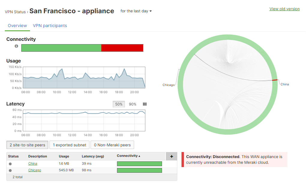
The following sections outline common issues with Auto VPN and recommended troubleshooting steps.
Configurations that use Automatic NAT Traversal
-
Site-to-site VPN: When MX Series WAN appliances are configured to create a VPN between two or more sites within the same Organization.
- Teleworker VPN: When MR Series access points have an SSID configured to tunnel all traffic back to a central concentrator. This concentrator can be either an MX Series WAN appliance in passthrough/concentrator mode, or a VM (Virtual Machine) concentrator.
Troubleshooting VPN connectivity issue
Users are unable to ping or access network resources on the remote network through the Auto VPN tunnel.
Possible causes
-
VPN Registry disconnected
-
Tunnel establishment issue
-
Route propagation issue
-
SD-WAN policy routing or misconfiguration
-
WAN appliance or third-party firewall policy conflict
Troubleshooting steps
If you are unable to connect to devices on the other network from your site:
-
Verify that both devices are online and connected to the VPN registry
- Navigate to Security & SD-WAN > Monitor > VPN status page to check the VPN status page on both networks.
- Verify that the subnet you are trying to reach is advertised over VPN
- On the remote network, navigate to Security & SD-WAN > Configure > Site-to-site VPN. Under Local networks, ensure the Use VPN toggle is set to Yes for the subnet you're trying to reach.
- Repeat the same check on your local site's dashboard network to ensure the subnet you're connecting from is also advertised.
- If using a full tunnel configuration, ensure that when specifying a prefix to be part of the VPN, all subnets within that prefix will be allowed in the VPN. Subnets that overlap will cause traffic in a more specific subnet to be sent through the VPN, even if it is not configured to be included in the VPN. For example, if 10.0.0.0/16 is configured to be included in the VPN but 10.0.1.0/24 is not, traffic sourced from 10.0.1.50 will still be sent over the VPN.
- Check for firewalls blocking this traffic on the network:
- Verify that no non-Meraki firewalls on the network blocking this traffic, including firewalls enabled on the device you're trying to access. navigate to Security & SD-WAN > Configure > Site-to-site VPN > Organization-wide settings section to confirm if there are any Site-to-site outbound firewall rules.
- Check if problems reach out to non-VPN peers
- Send pings or traceroutes to public IP addresses (such as 8.8.8.8) or access public websites to determine whether the problem is strictly related to VPN.
- Ping the public IP address of the other WAN appliance from your local network. If this fails but general internet connectivity is working, an upstream ISP routing issue is likely preventing the two sites from communicating directly, even though both sites have internet access and are connected to the VPN registry.
- Check if routes configured on both sides that point to the remote subnets:
- If the WAN appliance is not the only gateway in the network (for example, the WAN appliance is connected to a Layer 3 switch or router with its own directly connected networks), any devices that are not using the WAN appliance as their gateway will need their traffic routed to the WAN appliance to send traffic across the VPN. Ensure any other routing devices on the network have a route that allows them to access the remote VPN subnets via the WAN Appliance's local IP address.
- For extensive details on deploying the WAN appliance as a VPN concentrator, refer to VPN Concentrator Deployment Guide.
- Check whether the devices are on non-overlapping subnets:
- If the device on each end is on a subnet that overlaps with the other side, the WAN appliance will be unable to route traffic to the remote network because the appliance will treat the traffic as destined for the local network. Each network connected to the VPN should use unique subnets with no overlap.
- If identical networks are required on each side of a tunnel, you may need to enable VPN Subnet Translation. VPN Subnet Translation does not support partial overlap between subnets. Subnet translation is supported for AutoVPN and IPSEC VPN configurations.
Expected outcome
By completing the checks above, you should be able to determine whether the issue is caused by tunnel health, route advertisement, policy/firewall filtering, upstream path problems, or subnet design conflicts, and isolate the exact remediation point.
- VPN registry and tunnel health validated
- Required subnets confirmed as VPN-advertised
- Firewall and policy path cleared
- Problem scope identified (VPN-only vs general connectivity)
- Routing dependency validated
- Subnet overlap ruled out or translated
- Service restoration verified
Escalation
If all checks pass and connectivity still fails, the expected outcome is a narrowed fault domain (ISP transit, upstream firewall/NAT behavior, or platform-level tunnel negotiation) ready for escalation with evidence from VPN status, route tables, and path testing results.
-
Contact ISP (both sites): Ask them to check routing/path issues between the two WAN public IPs.
-
Contact Firewall/Security team: Confirm no firewall or NAT rule is blocking VPN subnet traffic.
-
Contact Internal Network team: Confirm LAN routing points remote subnets to the MX and no subnet overlap exists.
-
Contact Meraki Support: Ask them to verify Auto VPN tunnel health, route advertisement, and registry status.
Troubleshooting VPN registry and NAT issue
VPN status page reports an unfriendly NAT or disconnected from VPN Registry
If the Security & SD-WAN > Monitor > VPN status page for a given network reports either "NAT type: Unfriendly" or "VPN Registry: Disconnected", there is likely a device upstream of the WAN Appliance for that site that is preventing Auto VPN from working correctly.
When using VPN functionality to securely tunnel traffic between Auto VPN capable devices, such as the WAN appliance Site-to-site VPN, or access point Teleworker VPN, the devices must first register with the dashboard VPN registry. This allows their connections between each other to be dynamic and automatically established without manual configuration. However, sometimes issues can occur with this process.
To ensure connectivity, each Auto VPN node sends a keepalive message to the VPN Registry every 10 seconds. If more than six keepalives are not received by the registry, that node is marked as disconnected. For information on how connectivity to the VPN Registry works, refer to the Automatic NAT Traversal.
Both Auto VPN peers must be in communication with the VPN registry to get the correct information to form a valid VPN tunnel. If one Auto VPN node, such as an MX WAN appliance, can reach the VPN registry, but the intended peer WAN Appliance is not, the tunnel will not form. A common occurrence of this is when an upstream firewall blocks VPN registry communication on UDP port 9350–9381. This issue is explained in the section VPN Registry Disconnected.
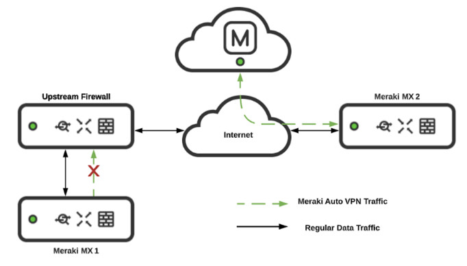
If the appliance/concentrator is successfully connected to the VPN registry but is disconnected from another VPN peer, refer to the troubleshooting steps.
-
NAT type: Unfriendly indicates that the upstream NAT won't allow the WAN Appliance to use UDP hole punching to form the tunnel. It is recommended to set NAT traversal to Manual: Port forwarding to bypass this issue.
- VPN Registry: Disconnected indicates that the upstream device is not allowing the WAN Appliance to communicate with the VPN registry. It is recommended to configure any upstream firewalls to allow the traffic listed in dashboard under Help > Firewall info.
Possible causes
-
An upstream firewall blocks or modifies VPN registry communication on UDP port 9350–9381, preventing the tunnel from forming even if one peer can reach the VPN registry.
Troubleshooting steps
Refer to the subsections below based on the error reported on the Security & SD-WAN > Monitor > VPN status page:
-
If VPN registry: disconnected is reported → refer to the VPN registry disconnected
-
If NAT type: unfriendly is reported → refer to the NAT type: unfriendly
Expected outcome
By following the workflow for the reported status, you should isolate whether the failure is caused by upstream NAT/firewall behavior versus a peer-to-peer VPN issue.
- WAN appliance connectivity to the registry is confirmed
- Error condition is correctly classified
- VPN registry: disconnected (cannot reach registry), or
- NAT type: unfriendly (registry reachable, but tunnel negotiation path is blocked by NAT behavior).
- Root cause domain is narrowed
- You can determine if the blocking point is an upstream firewall/NAT device (UDP 9350-9381 filtering, rewriting, or timeout behavior).
- Service impact is validated after fix
Escalation
-
ISP / upstream network provider
Request validation of UDP 9350-9381 handling, NAT behavior, routing symmetry, and any filtering between site WAN egress and Meraki registry endpoints.
-
Firewall/Security team
Review and update upstream firewall/NAT rules to allow unmodified outbound/return registry traffic and stable UDP session handling.
-
Meraki Support
If policy and ISP path checks pass but status remains disconnected/unfriendly, open a case with org/network IDs, appliance serials, VPN status screenshots, event logs, and test timestamps for deeper registry/NAT traversal analysis.
VPN registry disconnected
When the "VPN registry: disconnected" message appears on the Security & SD-WAN > Monitor > VPN status page for WAN Appliance networks, it indicates that the appliance has been unable to establish connectivity with the VPN registry.

Expected behavior: If the WAN Appliance loses connectivity to the VPN registry, peer information gets purged over time but not immediately. Connectivity to the registry matters when a node changes its contact information after losing connectivity to the VPN registry. Both the hub and spoke will still be able to form the tunnel if the contact information remains the same, and they lose registry connectivity. Peer information will purge after a few hours, causing the tunnel to be marked down.
Possible causes
-
VPN registry: Disconnected — A firewall or other upstream device is either preventing traffic from reaching the VPN registry, or from returning to the appliance.
Cause indicator / symptom
-
"VPN Registry: Disconnected" message appears on the Security & SD-WAN > Monitor > VPN status page.
-
A firewall or other upstream device is either preventing traffic from reaching the VPN registry, or from returning to the appliance.
Troubleshooting steps
-
Review the packet capture to identify the issue.
-
In the example packet capture below, a WAN appliance is attempting to reach the VPN registry on UDP port 9350 but is receiving no response because an upstream firewall is preventing the outbound traffic.

- In this example, the appropriate firewall rules have been added to allow the traffic to the VPN registry, and responses can be seen.

-
A step to configure upstream firewall rules to allow VPN registry traffic.
-
Make sure that any upstream firewalls are configured to allow traffic to the IP addresses and ports listed on the Help > Firewall info page, particularly for the VPN registry. It should also allow return traffic from established connections (this is allowed by default for stateful firewalls).

Expected outcome
By completing these checks, you should confirm whether the appliance is truly unable to reach the VPN registry and isolate the blocking point to upstream firewall/NAT path behavior.
- Registry connectivity state is verified
- Upstream policy path is validated
- Required allow rules are applied
- Recovery is confirmed
- Tunnel resiliency behavior is understood
Escalation
- Firewall/Security team: Provide packet capture evidence showing missing outbound or return UDP 9350-9381 flow and request explicit policy/NAT/session-timeout review.
- ISP / upstream provider: If firewall policy appears correct, request path verification to Meraki registry endpoints and confirmation that UDP traffic is not filtered, translated incorrectly, or asymmetrically routed.
- Meraki Support: If both upstream firewall and provider checks pass, open a case with organization/network IDs, appliance serials, VPN status screenshots, packet captures (before/after), and timestamps for deeper registry-side troubleshooting.
NAT type: unfriendly
UDP hole-punching, the mechanism used to establish the VPN connections between Auto VPN devices, relies on a consistent IP address and port for both devices involved. Two VPN registry servers are used for redundancy, and both expect to see the device as available on the same public IP address and port.
However, some NAT devices (such as a firewall) will rewrite the source ports differently for each VPN registry server. Other NAT devices or load balancers will attempt to spread the connections to each VPN registry server across two different public IP addresses. Both cases will result in the VPN connection failing and marking the NAT as unfriendly.

Auto VPN peers can use Automatic NAT Traversal to establish a secure IPsec tunnel through a firewall or NAT. When ACLs on an upstream firewall block source ports or, more commonly, destination UDP ports in the range 32768–61000 on outbound traffic, a peer will not be able to punch a hole in the firewall and establish a tunnel with other remote peers.
Possible causes
-
Failed connectivity tests or a VPN status of "Disconnected" indicates a tunnel failure between peers in dashboard.
-
In a site-to-site VPN, if two peers are unable to establish a VPN connection, they will show as disconnected on each other's VPN status page.
In the example below, the firewall blocks peer1 from sending outbound UDP packets in the necessary destination port range. This prevents a hole punch. Now when peer2 tries to send inbound packets, its packets are dropped on the outside interface of the firewall because they do not match an existing outbound session. In this instance, the tunnel will not be established between peer1 and peer2.
Example: The upstream firewall rewrites the source port for each outbound connection differently. Notice that the first connection is changed to port 56125 while the second is instead 56126. When the registry servers see different source ports, the NAT unfriendly error will appear.

In this example the upstream firewall is load balancing connections over two WAN connections and then performing NAT using two different public IP addresses. Notice that the first connection is sent from the 198.51.100.23 address, while the second is sent from 198.51.100.17 instead. When the registry servers see different source IP addresses, the NAT unfriendly error will appear.

Solutions
If using a load balancer, or NAT across multiple public IP addresses, map traffic from the internal address of the appliance to a single public IP address. This will keep the public IP address seen by the VPN registry consistent.
-OR-
Select an arbitrary port that will be used for all VPN traffic to this WAN appliance (e.g. UDP port 51625). Manually create a port mapping on the upstream firewall that will forward all traffic received on a specific public IP and port to the internal address of the appliance on the selected port. In the dashboard on the Security & SD-WAN > Configure > Site-to-site VPN page use the Manual: Port forwarding option for NAT traversal, and provide the public IP address and port that was configured. All peers will then connect using this IP address and port combination.
Troubleshooting Automatic NAT Traversal
Cisco Meraki VPN peers can use Automatic NAT Traversal to establish a secure IPsec tunnel through a firewall or NAT. When ACLs on an upstream firewall block source ports or more likely the case destination UDP ports in the range 32768-61000 on outbound traffic, a peer will not be able to punch a hole in the firewall and establish a tunnel with other remote peers.
Cisco Meraki VPN peers must be able to use high number UDP ports to communicate with each other. Security systems such as firewalls that disallow this traffic may prevent successful traffic flow over the VPN. Please follow the diagnostic and troubleshooting steps below to resolve such issues.
In the example below, the firewall blocks peer1 from sending outbound UDP packets in the necessary destination port range. This prevents a hole punch. Now when peer2 tries to send inbound packets, its packets are dropped on the outside interface of the firewall because they do not match an existing outbound session. In this instance the tunnel will not be established between peer1 and peer2.

Failed connectivity tests or a VPN status of 'disconnected' indicates a tunnel failure between peers in the dashboard.
Troubleshooting steps
-
Take a packet capture to identify the blocking firewall
-
In a site-to-site VPN, if two peers are unable to establish a VPN connection, they will show as disconnected on each other's VPN status page. In this case, a packet capture should be taken on the primary Internet interface of both peers to analyze which firewall is blocking IPsec communication.
- Analyze a Packet Capture for IPsec Connectivity
-
Packet captures can be taken from the dashboard and downloaded as a .pcap file for analysis and filtering using Wireshark packet analyzer. They are invaluable for troubleshooting connections between hosts and isolating connectivity issues.
-
In the example below, there is an Access Point to VPN concentrator tunnel that will not establish. Packet captures are taken from different points in the path to help determine which firewall is blocking the peer-to-peer communication:
Capture 1 — Wired interface of the Access Point (10.0.8.99):
- The first capture, shown below, was taken from the wired interface of the Access Point 10.0.8.99. We can see the Access Point attempting to punch a hole in its local upstream firewall by sending packets to 208.72.143.11, which is the outside IP address of the NAT that the VPN concentrator sits behind. Notice the Access Point is sending traffic to the concentrator but there is no return traffic in the capture from the WAN appliance behind the NAT.
- Access Point 10.0.8.99:45540 -> WAN Appliance 208.72.143.11:53654

Capture 2 — Inside interface of the WAN Appliance upstream from the VPN concentrator (VPN concentrator LAN IP: 10.0.50.246):
- A second capture, shown below, was taken from the inside interface of the WAN appliance upstream from the VPN concentrator. The VPN concentrator uses IP address 10.0.50.246 on the LAN. We can see the VPN concentrator sending packets to 208.72.143.18 which is the outside IP address of the NAT that the Access Point sits behind in an attempt to punch a hole in its local upstream firewall. Notice the VPN concentrator is sending traffic to the Access Point but no return traffic is present from the Access Point behind the NAT.
-
WAN Appliance 10.0.50.246:53654 -> Access Point 208.72.143.18:45540

Capture 3 — Outside interface of the WAN Appliance upstream from the VPN concentrator:
- A third capture was then taken, this time from the outside interface of the WAN Appliance upstream from the VPN concentrator. We can see the VPN concentrator's traffic has been translated to 208.72.143.11, which is the firewall's outside IP address, and that it is being forwarded onto the Internet. This indicates the firewall is not blocking outbound IPsec traffic in the VPN concentrator site. However, we do not see any traffic originating from 208.72.143.18, the IP address of the NAT device the Access Point sits behind. From this we can conclude that the firewall upstream from the Access Point is blocking outbound IPsec traffic within the UDP port range 32768–61000.
-
WAN Appliance 208.72.143.18:53654 -> Access Point 208.72.143.18:45540.

Capture 4 — Outside interface of the WAN appliance upstream from the access point:
- To confirm, we take a final capture from the outside interface of the WAN appliance upstream from the AP, shown below. This capture shows packets originating from the VPN concentrator at 208.72.143.11 and arriving at the AP firewall's outside interface at 208.72.143.18. We still do not see any traffic originating from the AP being sent from the outside interface. This indicates the WAN appliance is in fact blocking outbound IPsec traffic on the inside interface, specifically destination UDP port range 32768–61000.
-
WAN Appliance 208.72.143.18:53654 -> Access Point 208.72.143.18:45540.

-
Reconfigure the upstream firewall to allow outbound IPsec traffic
Once we reconfigure the firewall upstream from the AP to allow outbound destination port range 32768–61000, peers are able to form a tunnel. Although the first 4 captures are filtered by UDP ports 53654 and 45540, once the firewall is opened two-way traffic can occur on any dynamically chosen ports as shown below on a packet capture taken from the wired interface of the AP. Now the AP is registered with and using port 41091 for VPN communication:
-
Access Point 10.0.8.99:41091 -> WAN Appliance 208.72.143.11:53654
-
Access Point 10.0.8.99:41091 <- WAN Appliance 208.72.143.11:53654

-
Apply ACLs to allow peer-to-peer communication
Below are two examples of ACLs that could be used to allow peer-to-peer communication between Meraki VPN peers. For the second option, X.X.X.X/32 represents the IP address of the Meraki device.

OR

Troubleshooting Auto VPN using packet captures
Packet captures are useful to troubleshoot VPN connectivity. They are especially useful when traffic is not flowing as expected through the tunnel, or when the Auto VPN tunnel is failing to establish. The following sections outline the general approach for troubleshooting Auto VPN connectivity using packet captures.
Troubleshooting steps
Step 1 Identify source and destination sites
To troubleshoot VPN connectivity, identify the two sites that are having connectivity issues and the expected/intended traffic flow between those sites if the VPN was functioning. Begin by identifying the two sites involved in communication.
Once the sites have been identified, determine the expected traffic flow if the tunnel was functional. Identify where the connection is originating and the intended destination, the location of each of these will become the Source and Destination site/MX respectively.
Step 2 Identify Auto VPN traffic on the WAN
To identify the WAN traffic being passed between the two sites, the first step is to know the public IP and port, and the IP and port assigned to the currently active physical WAN interface of each Auto VPN node.
- From the Security & SD-WAN > Monitor > VPN Status page of each Auto VPN node, check the NAT type box to see both the physical WAN IP and the Public IP being used for the VPN connection. For each IP, a port will also be listed.
- Note the following considerations:
- If the Auto VPN node using a routable public address directly on its WAN interface, i.e., the WAN uplink is not behind a NAT, the public IP and physical WAN IP may be identical. If the public IP and physical WAN IP are the same, only one IP will be displayed in the NAT type box on the VPN Status page.
- If the MX is behind a NAT with different physical WAN and public IPs, the UDP port used by the public IP and the physical WAN IP may be the same, depending on the NAT type.
- If the NAT Type is Unfriendly, WAN IP and port details will not be displayed in the box, and the VPN-unfriendly NAT issue should be addressed first. Refer to the VPN-unfriendly NAT section for troubleshooting steps.
- When using WAN appliances in an HA configuration, a virtual IP may be used on the WAN interface in addition to the physical WAN IP. If a virtual IP is configured, inbound and outbound traffic for that node will use the virtual IP instead of the physical WAN IP.
Step 3 Identify LAN traffic
After gathering the necessary information to identify relevant WAN traffic in a packet capture, the next step is to gather IP and port information about the relevant traffic seen directly on the LAN of each site. In this case, the relevant traffic is directly related to the connectivity issue being troubleshoot.
-
The initial source IP and port(s) and the initial destination IP and port(s) being used by hosts on the LAN of the appliances on both sides.
-
If we do not know the specific port being used as the source or destination port, knowing the source and destination LAN IPs of both clients will allow you to, at least, confirm the ability for layer 3 traffic to pass over the VPN between the two sites as intended.
-
Return or response traffic generally uses the same port numbers as the initiating traffic, but in reverse.
Step 4 Collect and analyze packet captures
Once the source and destination sites and expected traffic flow are identified, collect packet captures from the dashboard to compare real and intended traffic flow. It helps you identify where the connection is failing.
To capture a complete view of the real traffic flow for a given moment, collect packet captures from LAN and Internet interfaces of both MXs at the same time. To collect multiple packet captures simultaneously, open the Network-wide > Packet Capture page in a separate tabs.
-
To view only the relevant traffic in the packet captures, apply filters based on the identified IP addresses and ports:
-
For Internet captures, use WAN IPs and ports.
-
For LAN captures, use LAN IPs and ports.
-
When a high amount of traffic is being passed through the interface, it is important to use filters since a single packet capture is limited to 100,000 packets.
-
If the MX has multiple WAN interfaces, make sure to select the active one when collecting packet captures.
Step 5 Access point to WAN appliance concentrator testing
With an Access Point to WAN appliance concentrator connection type:
- Use the Test connectivity button on the wireless network. Running the test will report which access points "failed to connect to the concentrator." If the issue is on the concentrator side, it is likely that all access points will fail the test.
- Take a packet capture on the wired interface of each Access Point that failed to connect to the concentrator.
- Take another capture from the primary Internet interface of the WAN appliance.
- Analyze these captures to determine which site's firewall is blocking outbound IPsec communication.
Packet Captures are a powerful tool to troubleshoot VPN connectivity. They can be especially useful in scenarios when traffic is not flowing as expected through the tunnel, or the Auto VPN tunnel is failing to establish. The following sections will outline the general approach for troubleshooting Auto VPN connectivity using packet captures.
Additional information
Configurations that use automatic NAT traversal
-
Site-to-site VPN: When MX Series WAN appliances are configured to create a VPN between two or more sites within the same Organization.
-
Teleworker VPN: When MR Series access points have an SSID configured to tunnel all traffic back to a central concentrator. This concentrator can be either an MX Series WAN appliance in passthrough/concentrator mode, or a VM (Virtual Machine) concentrator.