
MX Templates Best Practices
Click 日本語 forJapanese
As a network deployment grows to span multiple sites, managing individual devices can become highly cumbersome and unnecessary. To help alleviate these operating costs, the Meraki WAN Appliance offers the use of templates to quickly roll out new site deployments and make changes in bulk.
This guide will outline how to create and use WAN Appliance templates on the dashboard.
It should be noted that service providers or deployments that rely heavily on network management via API are encouraged to consider cloning networks instead of using templates, as the API options available for cloning currently provide more granular control than the API options available for templates.
Planning a Template Deployment for WAN Appliances
Before rolling out a template deployment (or enabling templates on a production network), it may be helpful to plan the "units" that make up your deployments. This involves asking questions such as:
-
What are my sites? (e.g. retail location, school, branch office, etc.)
-
Are the WAN Appliances going to be in HA?
-
Do I need local overrides?
Template Networks
A "site" in network deployment terms is usually the same as a "network" in dashboard terms; each site gets its own dashboard network. As such, when planning multiple sites to be configured the same way, they will share a template network.
A template network is a network configuration that is shared by multiple sites/networks. Individual site networks can be bound to a template network, so changes to the template will trickle down to all bound sites. A new network can also be created based on a template, making it easy to spin-up new sites of the same type.
When planning a template deployment, you should have one template network for each type of site.
Configuration
The following sections walk through the configuration and use of WAN Appliance templates in the dashboard.
Creating a Template Network
As outlined above, a template network should be created for each type of site to be deployed.
To create a template network:
-
In the dashboard, navigate to Organization > Monitor > Configuration templates
-
Choose Create a new template
-
Select a descriptive name for your template. If this is a completely new template, select Create new
-
If this template should be based on an existing network, select Copy settings from and select an existing Security appliance network from the drop-down menu.
-
-
Choose Add:
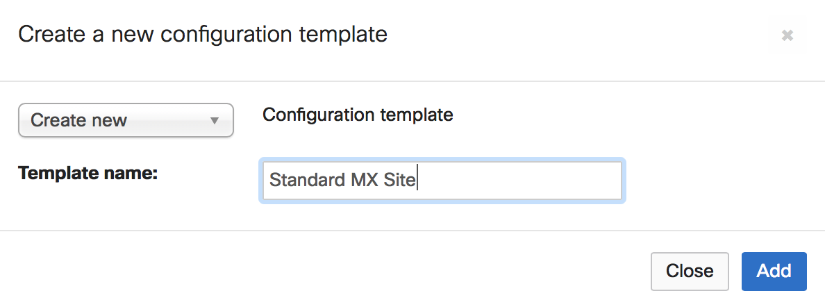
-
If you would like to bind existing networks to this new template, select those networks as Target networks and choose Bind. Otherwise, choose Close.
Template VLAN Configuration
-
In the dashboard, navigate to Security & SD-WAN > Configure > Addressing & VLANs
-
Under Routing section, LAN setting sub-section click VLANs
-
Choose Add VLAN under Subnets sub-section
-
Select a descriptive name for your VLAN
-
Choose whether the subnetting should be Same or Unique for every network bound to this template.
-
If Same is chosen, all the networks bound to the template will share the exact same subnet. This is not eligible for site-to-site VPNs.
-
If Unique is chosen, each network bound to the template will get a unique subnet based on the configured options. The MX does allow local VLAN overrides on templates, however, the chosen subnet needs to be from the same subnet pool assigned to the VLAN on the template and you can't override the VLAN ID.
-
Subnets are assigned randomly to each network bound to the template.
-
-
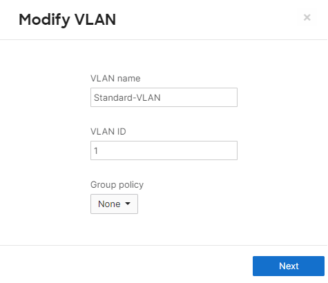
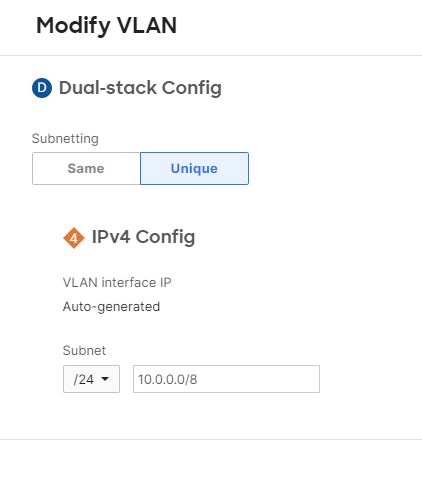
For more information about template IP range VLAN allocation, reference our article on Managing Networks with Configuration Templates.
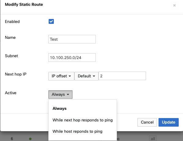
Template Static Routes
In template-based WAN Appliance deployments, static routes can be configured on the parent template and passed to child networks like other configuration parameters. The procedure for configuring a template-based static route is almost identical to the procedure for a regular network, with the exception of how next-hop IP addresses are defined as the next-hop value may be network specific.
-
In the dashboard, navigate to Security & SD-WAN > Configure > Addressing & VLANs > Routing > Static Routes
-
Choose Add Static Route
-
Name
-
Text description for the static route(not parsed)
-
Ex: prodWirelessNet
-
-
-
Subnet
-
Subnet reachable via static route specified in CIDR notation
-
Ex: 10.0.10.0/24
-
-
-
Next Hop IP
-
Next-hop IP is the IP address of the device that connects the WAN Appliance to this route. There are two methods for specifying next-hop values on template-based networks.
-
Option A: IP Assignment
-
Manually define next-hop value
-
Required Info:
-
Next-hop IP address
-
-
-
Option B: IP offset
-
Calculate next-hop IP based on network address for specified VLAN
-
NOTE: Next Hop IP will be calculated as Network Address + Offset and not VLAN Interface IP + Offset
-
-
IP offset parameters:
-
Select the desired VLAN from the dropdown
-
Offset value (a positive integer)
-
-
Example:
-
VLAN configured: 10.0.254.0/30
-
VLAN Interface IP: 10.0.254.1
-
Offset: 2
-
Calculated route next-hop IP: 10.0.254.2
-
-
-
-
-
Active
-
The active modifier controls conditions that must be met for the WAN Appliance to deem the route usable and add the route to the local routing table.
-
Always:
-
The route will always be active in WAN Appliance's routing table
-
-
While next-hop responds to ping:
-
The route is available as long as the configured next hop is responding to pings
-
-
While host responds to ping:
-
The route is available as long as the configured host is responding to pings
-
-
-
Template Firewall Rules
When configuring layer 3 firewall rules, CIDR notation, VLAN Objects and Network Objects can be used. The VLAN Object is used when the entire subnet needs to be specified whereas CIDR notation is used when more flexibility is needed to specify the subnets.
-
Go to Security & SD-WAN > Configure > Firewall > Layer 3, click Add a rule
-
Choose the policy, specify if the rule matched should be allowed or denied
-
Select the protocol to match in outbound traffic
-
Specify the IP address or range using CIDR notation to match the outbound traffic. Note that also the name of the VLAN can be chosen as well
-
Choose the Src/dst port to match in outbound traffic

IP Offset
If you wish to specify a single IP within a VLAN using a VLAN Object an IP Offset can be used to calculate the IP address that the rule will apply to based on the network address for the specified VLAN. The IP address will be calculated using the Network Address + Offset and not the VLAN Interface IP + Offset.
For example, if you have a firewall rule containing the source Users.10 representing the Users VLAN with an IP Offset of 10 and the subnet of the Users VLAN is 192.168.100.0/24 then the source will be interpreted as 192.168.100.10.
IP Offset is not available when configuring a dual-stack firewall rule, to use an IP Offset it must be either an IPv4-only or IPv6-only rule.
Template SD-WAN Policies
-
SD-WAN policies can be configured to control and modify the flows for specific VPN traffic. You can have a specific type of traffic go over one Uplink over the other.
-
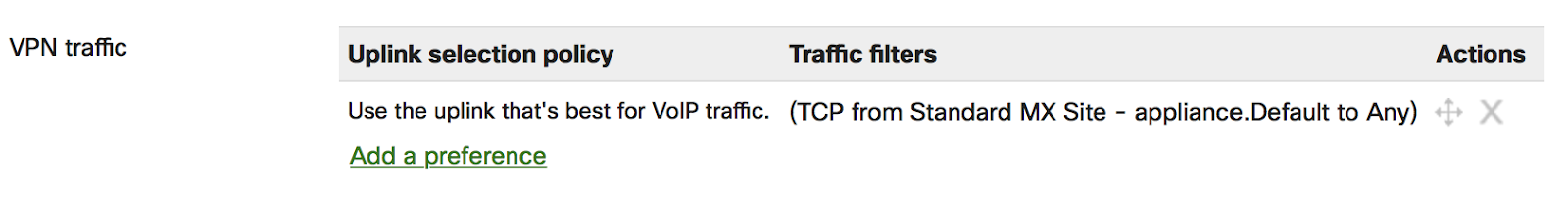
Go to Security & SD-WAN > Configure > SD-WAN & traffic shaping > SD-WAN policies > VPN traffic, and choose Add a preference
-
You'll be prompted with the Uplink selection policy dialog box. From this box, you can define the type of traffic that should adhere to the policy on the Traffic filters section. You can either add Custom expressions to select traffic based on Protocol/Source/Destination criteria, or you can select traffic based on pre-defined applications.
-
To add a custom expression to select traffic.
-
Choose Add +
-
The Custom expressions option should already be selected.
-
Choose the Protocol. You can choose either TCP, UDP, ICMP or Any
-
Choose Source to define the source address criteria. You can select one of the following:
-
You can choose Any
-
You can type in the source in CIDR format( eg: 10.0.0.0/8), and then choose Add
-
You can choose a VLAN from the drop-down menu with the list of VLANs and then choose Add VLAN
-
You can choose a VLAN from the drop-down menu with the list of VLANs and then click Host, type in the last octet of the host address, then choose on Add host
-
-
Choose the Src port. The Source port could be 'Any', a port number (eg: 2000), or a port range (eg: 2000-3000) within 1-65535.
-
Click Destination to define the source address criteria. You can select one of the following:
-
You can choose Any
-
You can type in the source in CIDR format( eg: 10.0.0.0/8), and then choose Add
-
You can choose a VLAN from the drop-down menu with the list of VLANs and then choose Add VLAN
-
You can choose a VLAN from the drop-down menu with the list of VLANs and then choose Host, type in the last octet of the host address, then choose Add host
-
-
Choose the Dst port. The Destination port could be 'Any', a port number (eg: 2000), or a port range (eg: 2000-3000) within 1-65535.
-
-
To add a pre-defined application to select traffic.
-
Select the application type from the menu and then the interesting application in question from the sub-menu (e.g., VoIP & video conferencing > Webex)
-
Add all the applications which you want them to adhere to the policy and then choose Add+ to exit the applications menu
-
-
-
Under the Policy section, you can select one of the following as the Preferred uplink
-
WAN1 or WAN2. If you choose WAN1 or WAN2, you'll have the opportunity to configure failover criteria under Fail over if drop-down menu. You can select either Poor performance and then choose one of the performance classes from the Performance class drop-down menu or you can choose Uplink down. By default, VoIP is the only pre-defined performance class. Any additional performance classes have to be defined under Security & SD-WAN > Configure > SD-WAN & traffic shaping > SD-WAN policies > Custom performance classes.
-
Best for VoIP. The uplink that is best for VoIP traffic will be chosen.
-
Load balance. The WAN Appliance will balance traffic across the uplinks that meet the performance class selected from On uplinks that meet performance class drop-down menu.
-
Global preference. The uplink will be chosen based on the configuration under Security & SD-WAN > Configure > SD-WAN & traffic shaping > Uplink selection > Global preferences.
-
Global bandwidth limits. When configuring this setting, keep in mind that the MX will apply and return the speed settings configured here at the template level as opposed to the network level. This may not reflect the affected device's hardware capabilities. Refer to https://developer.cisco.com/meraki/a...ink-bandwidth/ for more information
-
-
Once you are done with configuring the criteria to apply the policy and the policy, choose Save
Note:
The "add host" button under Security & SD-WAN> Configure > Traffic shaping > Flow preferences, gives an option to enter a value between 1-254. The following seems to be the expected behavior:
If we have a subnet /26 from 10.0.0.0/8, there would be 4 possible 4th octets: x.x.x.0/26 = .0-.63
x.x.x.64/26 = .64-.127
x.x.x.128/26 = .128-.191
x.x.x.192/26 = .192-.255
Since the template needs to be applicable to ALL networks tied to it, it uses an offset.
If we were to specify the .1 host, this would be the equivalent of .1, .65, .129, and .193 depending on the given network tied to the template.

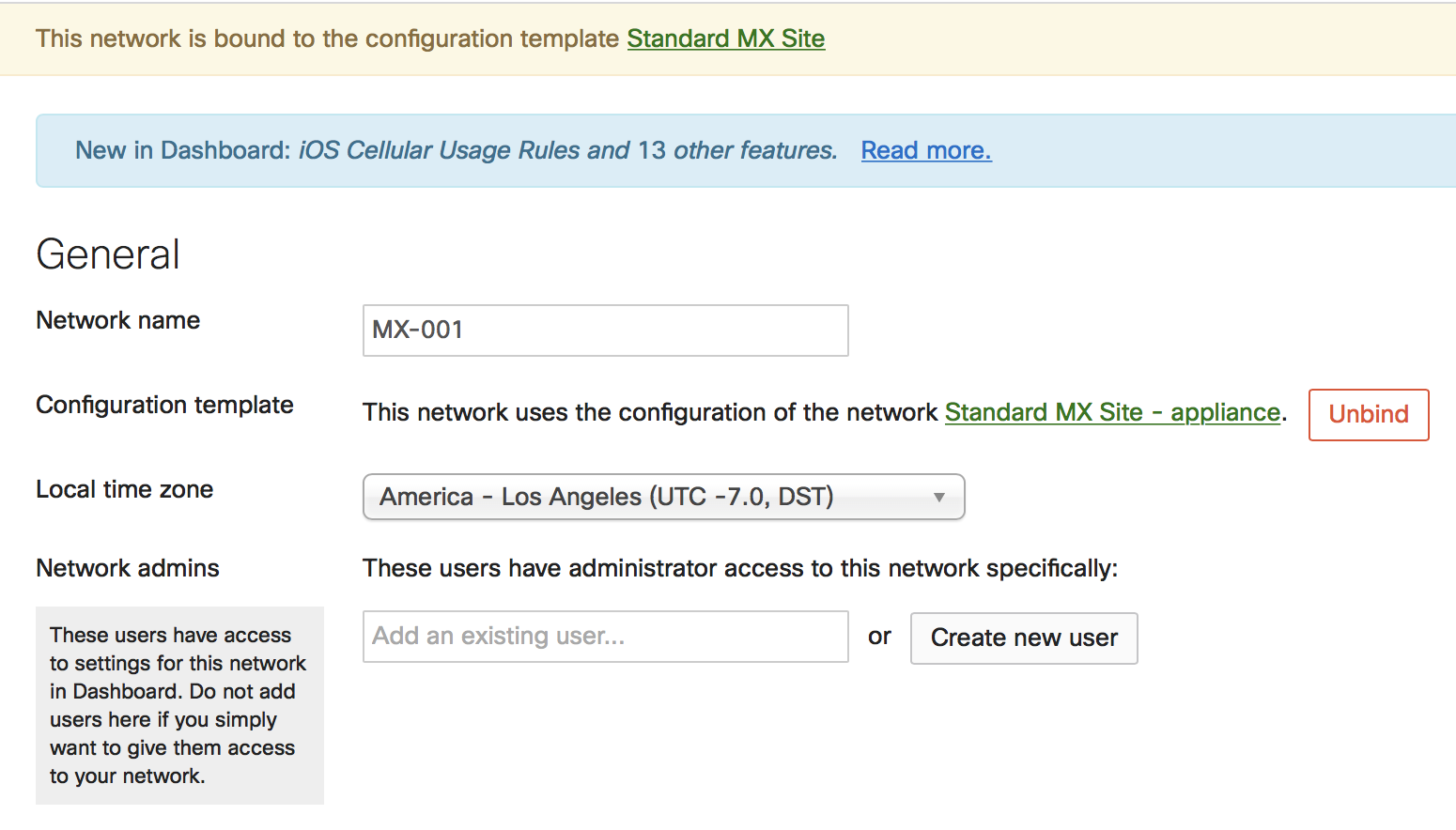
Local Overrides
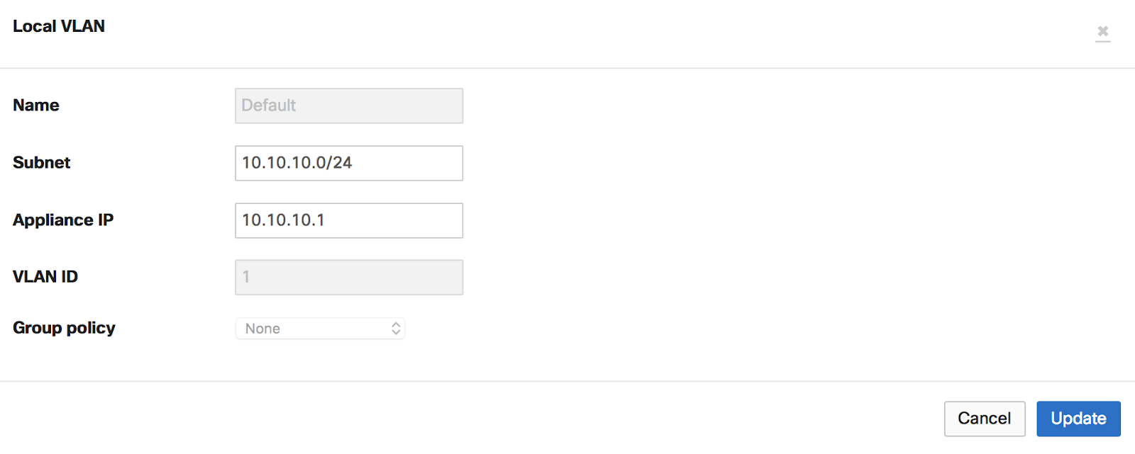
Once a WAN Appliance network has been bound to a template, some options can still be configured normally through the dashboard. Any local configuration changes made directly on the WAN Appliance network will override the template configuration.
In the example below, the bound WAN Appliance was directly configured to have a custom Default VLAN. This change can be made in the template network, under Security & SD-WAN > Configure > Addressing & VLANs:
If a network is removed from a template, local overrides will automatically be lost as well as any template related configuration. The WAN Appliance will automatically get the configuration from the network it is on.
Note: Auto VPN hubs should not be added to templates at all. It is not possible to configure a WAN Appliance as a spoke with an exit hub that is part of a template.
Note: Static Route local overrides are not supported at this moment for WAN Appliance networks bound to templates.
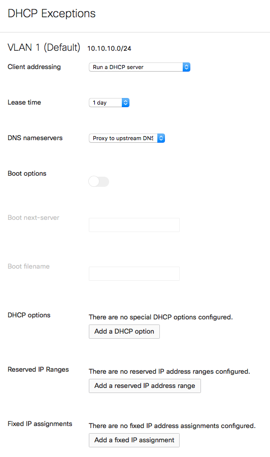
DHCP Exceptions
The Meraki WAN Appliance provides a fully-featured DHCP service that can be enabled and configured on each VLAN individually. When bound to a template, local overrides can be made to the DHCP configurations under Security & SD-WAN > Configure > DHCP.
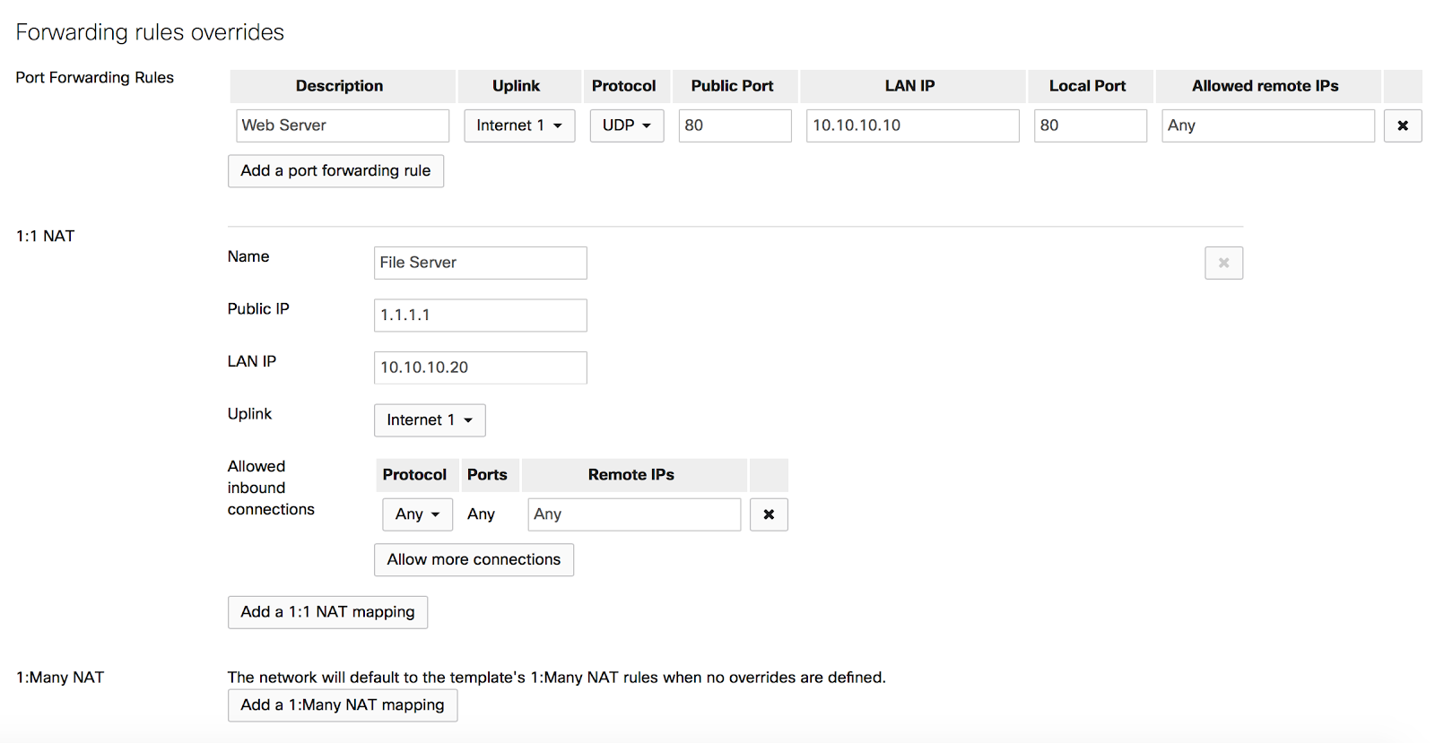
Forwarding Rules Overrides
To override forwarding rules, navigate under Security & SD-WAN > Configure > Firewall > Forwarding rules overrides.
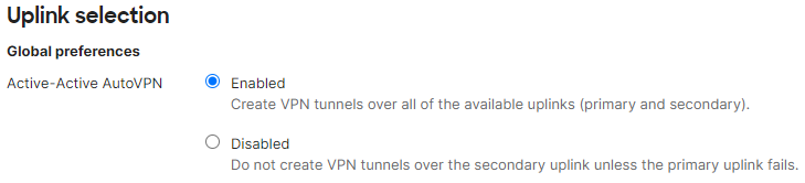
Active-Active AutoVPN
To override the uplink selection rules for Active-Active AutoVPN, navigate to Security & SD-WAN > Configure > SD-WAN & traffic shaping > Active-Active AutoVPN.
Templates with MXs of Different Port Counts
You can toggle the LAN2 port between LAN and Internet, through Uplink configuration under the Local status tab on the Local Status Page.
Client VPN
To manage client VPN users, navigate under Network-wide > Configure > Users
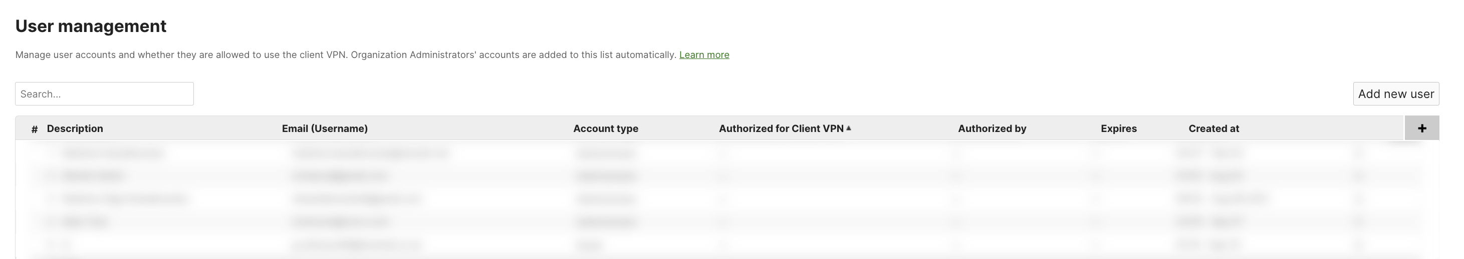
Note: To manage Client VPN users across all networks bound to a template, you can do so in the User Management section of the Security & SD-WAN > Client VPN page of said template. If you would like to manage Client VPN users for a specific network bound to that template, you can do so in the Network-wide > Configure > Users page of that network
For more detailed guidance on the above Client VPN setup, please refer to the Client VPN Overview document.
Performing MX Templates Firmware Upgrades
Firmware upgrades scheduled on the template will automatically be applied to the child networks’ network local timezone.
As a best practice, make sure that each MX has the correct local time zone configuration under Network-wide > Configure > General.
WAN Appliance Replacement Walkthrough
Below are instructions for how to copy configurations from a failed WAN Appliane bound to a template.
-
On the Organization > Configure > Inventory page, claim the new WAN Appliance.
-
Navigate to the network that has the faulty WAN Appliance and remove it under Security & SD-WAN > Monitor > Appliance Status > Remove appliance from network
-
Add the replacement WAN Appliance to the same network by navigating to Network-wide > Configure > Add devices
-
Select the network and choose Add devices.
For more information on replacing a WAN Appliance, refer to our MX Cold Swap article.