
Best Practice Design - MT
Overview
This article outlines best practices for deploying Cisco Meraki MT sensors, focusing on essential topics such as power requirements, placement, gateway compatibility, and data management. Readers will find guidance on optimizing sensor performance and ensuring secure, reliable integration within their network.
Physical Considerations
Power
Ensure that the configured e-mail alert recipients for any low battery or offline status alerts have an inbox that is monitored and accessible. Consider setting calendar reminders or plan for a battery replacement schedule, in case the low battery alerts are not seen or actioned in time.
For MT devices which contain PM2.5 sensors, note that sensor is disabled while on battery power. External power via the USB-C port is required collect PM2.5 data.
The MT40 provides schedules for power-saving functions.
The MT40 is placed in-line between an upstream power source and a downstream device's power supply. It uses the upstream power source for its own management functions. Refer to the MT40 Smart Power Controller FAQ for more information.
Placement
Mounting
Mount the sensors so they cannot be accidentally knocked off or removed by unauthorized persons. Attach the mount plate (if included) to the wall using screws. Use the security anchor screw to deter removal of the sensor by hand.
There are a few options for mounting a sensor:
a. Screws - The mounting plate can be directly screwed onto the wall.
b. Very High Bond (VHB) tape - Double-sided VHB tape can be used to stick the mounting plate on any type of surface. Note that VHB tape is intended to permanently attach the mounting plate to a surface. Exercise caution when attaching to painted surfaces, as it may be difficult to remove cleanly once it has been placed.
c. Magnet - Stick the magnet on any surface and the mounting plate can be stuck to the magnet.
d. Velcro Mounting Strap (MT40)

Refer to the relevant per-product installation guide for further details.
Environment
MT devices are designed for indoor use only. The maximum operational temperature and humidity limits in an environment can be found in each relevant product datasheet.
Gateway Coverage and Capacity
The optimum range between sensor and gateway is 15 feet (~4.5 meters). Distances may be greater than this, providing the minimum attainable signal strength is equal to or greater than -80 dBm.
If using an MR as the gateway device, the IoT/Bluetooth® Low-Energy (BLE) radio is only enabled on MR access points (APs) operating in full power mode (with PoE 802.3at, unless otherwise stated in each MR AP model's datasheet). If an AP is running in low power mode, MT sensors will not be able connect.
MT sensors contact the Meraki dashboard via Bluetooth® LE, which operates within the 2.4 GHz spectrum. As such, their range can be affected by the wireless environment, including both IEEE 802.11 and non-IEEE 802.11 sources of interference.
The supported sensor count being managed by a single gateway is up to a maximum of 32 MT sensors in regular sampling mode, or 8 in high sampling mode.
Proximity to Metric-Influencing Sources
Air Quality Sensors
For sensors that measure air quality (CO2, TVOC, PM2.5, temperature and humidity), consider the placement and orientation of these sensors ensures adequate airflow around the air intake port for accurate data capture. If these sensors are mounted in a location with limited airflow, it may take an extended period of time for the sensor to register a large change in temperature or humidity. They should not be placed near an inlet or outlet airflow vent, as these measurements are less likely to be representative of the overall air quality in the environment.
While PM2.5 levels (dust particles less than 2.5µm in size) can indicate the presence of the vapor from e-cigarettes, they also come from many other sources. Automobiles, construction sites, industrial facilities, fires, smokestacks, and cooking fumes can also generate PM2.5 pollution. Consider these factors to determine whether the presence of other sources can influence the objective source being measured.
Refer to the article Air Quality Metrics Explained for further information.
Water Leak Sensors
The leak detection cable needs time to dry out after coming into contact with water. The cable will be detected as wet with as little as 3 ml of normal water, which means if the cable becomes fully submerged, it could take a considerable amount of time to dry out fully. This is especially true if any water finds its way into the female end of the water detection cable.
When connecting the detection cable, there should be a ‘click’ sound when the cable fully seats, with nearly no gap between the ground sheaths of the male and female ends of the connectors.
MA-CBL-LEAK-1 is a leak detection cable that is sensitive to water across the length of the cable, providing leak detection across a wide area. This cable can also be daisy chained with another 8 feet cable, extending the total maximum coverage to 16 feet. 8x VHB sticky pads are provided which can be used to retain the cable in its desired placement.

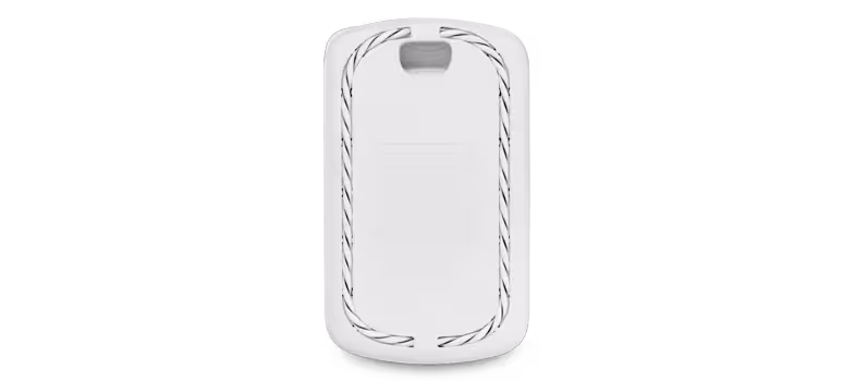
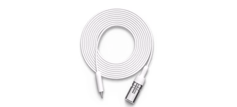
MA-CBL-LEAK-2 is a compact form factor "spot leak" detection cradle which houses the MT12 sensor and seats a cable in a coiled position around it. It is used to detect water leaks in a specific location. It is ideally placed directly below any location where water may travel, such as a valve or fluid pipe connector.
Temperature Probe Sensors
MA-CBL-TEMP-ME-1 is a bare-metal temperature probe designed to detect sudden temperature changes inside a cold storage environment.

MA-CBL-TEMP-GL-1 is a glycol-encased temperature probe designed to detect temperature changes over a longer period of time by insulating the probe against momentary fluctuations in temperature. As the probe is contained within glycol, it aims to reflect the temperature of goods within cold storage environments, as opposed to the ambient environment temperature itself.
Refer to the MT11 Probe Sensor Installation Guide for mounting and placement considerations.
Door State Sensors
The MT20 is calibrated to show as 'Closed' when the included magnet bar is at a distance between 5 - 20 millimeters (0.5 - 2 cm) away from the magnet symbol on the MT20 sensor. The magnet bar must be parallel to the MT20, and the magnet symbols on the MT20 and magnet bar must face each other.
Refer to the MT20 Installation Guide for instructions on mounting the MT20 and magnet bar.
Logical Considerations
Calibration
All sensors are either pre-calibrated during manufacturing or perform automatic self-calibration and cleaning, so no manual calibration is needed during their life cycle.
Total Volatile Organic Compound (TVOC) sampling requires a period of self-calibration, where the mechanism "learns" the environment it is installed in. Upon the first boot (immediately after un-boxing the sensor for the first time), the refinement period lasts up to 48 hours. This refinement period runs on every subsequent reboot, but at a reduced time period of a few hours. During the TVOC Refinement Period, the readings may not be accurate as the sensor is still calibrating the baseline metrics of the environment.
PM2.5 sampling doesn't require any calibration. However, the PM2.5 sensor does have a cleaning mechanism where it increases the speed of the fan at the bottom of the device, to eject any dust that may accumulate in the sensor port. This cleaning routine runs every 72 hours.
For best results, it is highly recommended to install the device with vents facing down to assist with both calibration and cleaning routines.
Compatible Gateways
Compatible gateway devices for MT sensors are as follows:
Data Exports
API
The dashboard API is used for pulling historical data and for viewing and modifying the settings configured on a dashboard organization. Refer to the API developer documentation for further guidance.
MQTT
MQTT is intended for real time data streaming, commonly used for a real-time view (relative to the update frequency per-sensor) of current data. It can also be used to collect data over a period of time by recording outputs at the broker/server side. Refer to MT MQTT Setup Guide for further guidance.
Tabular Data
A direct data download function is available on some dashboard pages through the download drop-down button. This provides outputs in common tabular data formats such as CSV, XML (for sensor data exporting) or XLSX (inventory of sensors list exporting).
Sampling Rate
The measurement frequency per-metric can be found in each sensor datasheet. Some devices such as the MT14 have selectable higher sampling rate modes, which increase both the sample polling frequency and power consumption.
Dashboard Administration
Administrators
The IoT Admin role allows for specific sensor-only administrator permissions, by restricting access and permissions of other parts of the dashboard network(s) and organization. See the article Camera and sensor-only admin (IoT Admin) for further information.
Alert Profiles
Specific values for alert profiles that account for all possible requirements cannot be suggested or determined out-of-context. The circumstance in each scenario mandates that testing be performed within each environment, to determine which threshold setting is suitable against the stated objective. For example, PM2.5 levels (dust particles less than 2.5µm in size) can be used to indicate the presence of the vapor from e-cigarettes, but it also can be emitted from many sources including automobiles, construction sites, industrial facilities, fires, smokestacks and cooking fumes.
Refer to the article Sensor Alert Profiles for more information.
Claiming Devices
Each MT sensor is shipped with a barcode label that can be scanned in the Meraki mobile app, which quickly claims them to a dashboard organization. In the Devices tab on the app, select the "+" icon on the top right of the screen and pick Scan new device barcode, then use the camera to scan each barcode.
Combined Dashboard Networks
MT devices must be in a combined network which contains compatible MR or MV gateways, as they rely on these gateways for dashboard connectivity. Any MT devices in a standalone Environmental network (which can occur via splitting a combined network) will lose dashboard connectivity until they are back in a combined network containing compatible MR or MV gateways.
Configuration Templates
Refer to the documentation for MT Template Best Practices.
Event Log Messages
The event log outputs messages for MT events, to help monitor and manage the sensor states easily. Refer to the article Common Sensor (MT) Event Log Messages for more information.
Firmware
The minimum firmware version for gateway devices are as follows:
MT40-Specific
Licensing
MT sensors require an MT license to operate. These licenses are generic and will apply to any MT device in the dashboard. They are not hardware- or SKU-specific.
Five free licenses for MT sensors are provided to all new and existing organizations, and these licenses do not expire.
Free MT licenses cannot be transferred to another organization, in either co-termination or Per-Device Licensing model. Free licensing for MT is not available in Subscription model.
Each organization receives 5 free MT licenses. Additionally, all new and existing co-term organizations with MR Advanced (MR-ADV) licenses will get two free MT licenses (MT-FREE-LIC) for each MR-ADV license.
Network Security
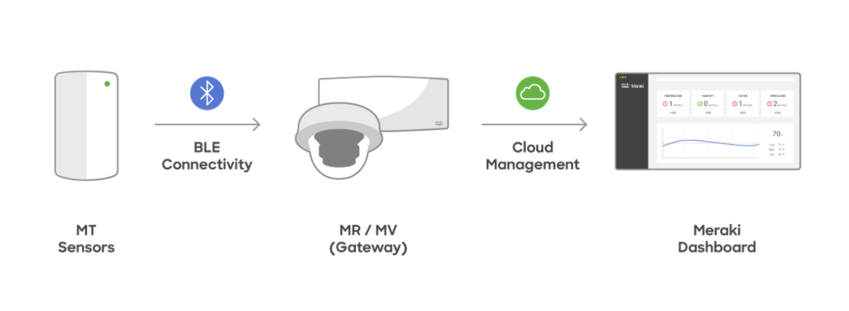
The Cisco Meraki Sensors use Bluetooth Low Energy radio to communicate with their gateways (MV and MR). Because BLE is used for communication, an IP stack is not required. This enables users to deploy Meraki MT sensors across their physical infrastructure without having to account for network segmentation, which is common for other IoT solutions. It helps the organization reduce challenges often incurred to ensure network security and further reduce network surfaced attack vectors.
The telemetry data from the sensors is sent to the gateway using a data encryption mechanism described below. The gateway then uses its existing connectivity to the Cisco Meraki Cloud to transfer the data. More details on the communication mechanism on the gateway can be found here.
More information on can be found on the MT Sensors Security Architecture KB article.