
Troubleshooting MV Image Quality
Overview
This article reviews possible causes for poor image quality and how to mitigate them.
Prerequisites
Review the following articles to get the best image quality:
- For any Cisco Meraki MV smart camera deployment:
- If you are using a fisheye form factor camera:
- For outdoor MV camera deployments:
If you have followed all best practice recommendations in the above articles and continue to see image quality issues, review the examples provided in this article for further mitigation steps.
Brightness and exposure
The image is too bright
External light sources
When excessive natural and artificial lighting is present, the image may appear washed out. This effect may be worse when reflective surfaces are in the scene. The following image shows an example of a washed-out scene caused by excessive light:

Solving an image that is too bright
Change the external light sources
Change the power output or positioning of any artificial lighting around the camera, or reposition the camera, to avoid excessive light from entering the lens. Introduce shade with blinds or curtains to reduce natural light.
Enable High Dynamic Range
High Dynamic Range (HDR) is an image-correcting feature that modifies the exposure of bright and dark areas of the scene. Enable HDR (where applicable) to reduce excessive exposure in lighter areas. The following image shows the same scene from the above section with HDR enabled:

The image is too dark
Aperture
The aperture of a lens is the opening that lets light through to the camera sensor. A small aperture setting provides the greatest depth of field, but it can also prevent sufficient ambient light from hitting the sensor through the lens, resulting in a dark image. On the Meraki dashboard, the aperture is smaller when the slider is set to the More in focus side:

Ambient and IR light levels
The ambient light levels may not be sufficient for the current aperture setting. The IR LED lights may be disabled via the configuration in the dashboard, or the power of the IR light cast out may be insufficient for the distance between the camera and the object of interest. Refer to the specific model datasheet for expected IR illumination distances.
Solving an image that is too dark
Aperture setting
Increase the size of the aperture by moving the slider toward the Reduced noise side. Testing the aperture in both light and dark scenes is recommended to get the best balance of brightness and sharpness, as increasing the aperture size may reduce the focus on objects in the scene.
Increase ambient and IR light levels
Add artificial lighting to the scene.
For daytime operation, increase ambient light by removing shade from natural light sources, such as blinds or curtains.
For nighttime operation:
- Enable IR LED operation on the camera.
- Move the camera closer to the object of interest.
- Add external IR lighting.
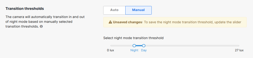
Modify the low light mode settings
Ensure both schedules are set accordingly:

Review the manual low light mode threshold setting, for earlier activation and later deactivation of the low light mode function.
Enable High Dynamic Range
HDR is an image-correcting feature that modifies the exposure of bright and dark areas of the scene. Enable HDR (where applicable) to increase visibility of darker areas in the scene.

Contact Support
If the above troubleshooting steps do not change the state, contact support for next steps.
IR reflection from surfaces
In the example below, the camera is deployed directly underneath a surface and at an angle that causes IR light to reflect back onto the camera lens. A similar scenario can occur when a camera is deployed behind a glass window, causing IR light to reflect back into the lens:
Solving IR reflection from surfaces
Deployment
- Avoid mounting the camera in close proximity to highly reflective surfaces such as glass windows, polished metal panels, white-painted walls, or other glossy materials that may bounce IR light back into the lens.
- Ensure that the camera's field of view is free of nearby obstructions—such as eaves, overhangs, or signage—that could bounce IR light back toward the lens.
- Adjust the lens angle slightly downward or away from reflective surfaces.
- If persistent IR reflection issues occur after troubleshooting, disable the camera's built-in IR LEDs and deploy external IR illuminators positioned at an angle offset from the lens to provide indirect infrared lighting across the scene.
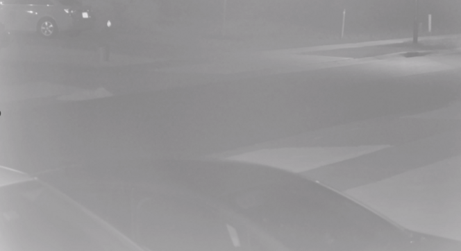
IR reflection from dust or dirt on the dome
The following images show examples of IR reflection caused by a dirty dome during night mode operation, and the same view after the dome has been cleaned.
Example 1:


Example 2:


Example 3:


Solving IR reflection from dust or dirt on the dome
Cleaning
Clean all dome cameras every six months to avoid IR reflection. Use a can of compressed air or a lightly dampened microfiber cloth to clear dust and debris from the dome surface.
Harsh chemicals can damage the camera dome and void the warranty. Refer to Guidance for Cleaning/Decontaminating Cisco Meraki Hardware for more information on cleaning recommendations.
IR reflection from condensation
Reflection can occur due to condensation or water inside the dome or on the surface. Condensation can form due to a poor seal from improper camera installation or failure to replace the desiccant pack during first-time installation. The desiccant pack is a small white rectangular-shaped packet used to absorb moisture.

The following image shows an example of IR reflection caused by condensation:

The following image shows the same camera during the day, illustrating how condensation affects image quality without IR illumination:

Solving IR reflection from condensation
Replacing the desiccant pack
Over time, the desiccant pack may lose efficiency in lowering ambient humidity, resulting in condensation buildup on the inside of the dome. Replace the desiccant pack with the spare pack (where provided).
Ensure the lens gasket is seated correctly
See Ensure the lens gasket is seated correctly below.
IR reflection from a poor lens gasket seal against the dome
The following image shows an example of IR reflection caused by a poor gasket seal:

The following image shows the same camera with a correctly seated gasket sealed against the dome:

Solving IR reflection from a poor lens gasket seal against the dome
Ensure the lens gasket is seated correctly
If the lens gasket is not sealed against the dome optic, IR light can reflect off the interior. This can occur when the rubber lens gasket is removed during camera installation.
Ensure the gasket is seated correctly when replacing the dome cover. It may be necessary to remove the gasket and lightly place it back on the lens, allowing the gasket to compress against the dome when the dome is closed.
The following image shows an MV21 with the gasket seated correctly:

The following image shows an MV21 with an improper gasket placement:

The following image shows an MV21 with no gasket installed:

Color
A red, pink, or purple hue is visible
IR light is not being filtered
Camera sensors can capture ranges of the light spectrum that are wider than the human eye can see. MV cameras contain a mechanical Infrared (IR) filter that reflects specific wavelengths of IR light to produce an image that more accurately represents what the human eye sees. Occasionally, the filter does not engage as expected, leading to a hue visible over the image during daylight hours:

Solving a red, pink, or purple hue
Toggle the low light mode setting
- Toggle to Always off and select Save.
- Wait a short while for the configuration to update, then toggle to Always on and select Save. The video feed should show when this change has been applied.
- Wait a short while for the configuration to update, then toggle to Always off and select Save. The video feed should show when this change has been applied.
- Review the live footage to confirm that the hue is no longer present.
Reboot the camera
Rebooting the camera causes the filter to toggle states. Review the live footage after the reboot to confirm whether the scene has changed.
Contact support
If toggling through the low light mode states and a reboot do not change the scene, contact support for next steps.
Vertical lines of color in the image
Damage to the image sensor
Vertical lines of solid color that span the image from top to bottom may indicate damage to the image sensor.
Solving vertical lines of color in the image
Reboot the camera
Reboot the camera. Review the live footage after the reboot to confirm whether the scene has changed.
Contact support
If damage to the image sensor is suspected, contact support for next steps.
Image artifacts
Flickering, banding, or moving streaks in the image
Artificial lighting
Flickering, banding, or moving streaks in the image can result from the rapid on-and-off cycling of artificial lighting, where a difference in frequency between the camera shutter speed and the lighting flicker is present.
Solving flickering, banding, or streaks in the image
Camera frequency configuration setting
The camera frequency setting under Network-Wide > General can reduce flicker by synchronizing the camera's shutter speed frequency with that of the artificial lighting in the scene.

Static pixels in the image
Damage to the image sensor
A grouping of solid-colored pixels that do not change position with movement in the scene may indicate damage to the image sensor.
Solving static pixels in the image
Reboot the camera
Reboot the camera. Review the live footage after the reboot to confirm whether the scene has changed.
Contact support
If damage to the image sensor is suspected, contact support for next steps.
Sharpness
The image appears blurred or pixelated
Focus
To achieve the clearest image of intended subjects in a given scene, the distance between the components of the lens and the image sensor must be adjusted. Auto focus functions can estimate the value based on an algorithm, but this may set the focus on an unintended part of the scene. Manual focus values can also be set incorrectly.
An example of an in-focus scene:

The same scene, out of focus:

Aperture
A large aperture setting set to the Reduced noise end of the slider may reduce the focus of the scene.

Video resolution
The resolution setting and maximum resolution capability of a camera can affect how sharp an image appears. Scenes captured at lower resolutions, especially at greater distances, may appear blurred due to pixelation:


Video quality (bit rate and frame rate)
A lower bit rate results in more compression, which may cause loss of detail in some pixels. Adaptive bit rate streaming reduces the bit rate based on the size of the video window. This is typically seen on video walls where multiple cameras reduce the size of each video window element. A lower frame rate may cause blurriness in moving objects.
The following images show zoomed-in views of a scene at the same resolution with a higher and lower bit rate. At the lower bit rate, there is a reduction in detail and more noise visible around the letters "COMPOST":
1080p at Enhanced Quality (3138 kbps at 20 fps):


1080p at Standard Quality (1024 kbps at 8 fps):


Solving an image that appears blurred or pixelated
Focus
- Use one of the two auto focus options (where applicable) and observe the outcome.
- If the desired area of focus is not achieved, select the Manual focus option and move the slider, testing different values.
- If the desired area of focus is still not achieved, contact support for next steps.


Aperture
Set the slider to the More in focus side of the aperture setting.
Video resolution
Set cameras to a higher resolution (where possible) to increase the perceived sharpness of the scene.

Increasing the resolution may reduce the video retention limit of a camera. The Smart Retention feature dynamically changes the resolution based on motion in the scene.
Video quality (bit rate and frame rate)
Set a higher video quality setting (where possible) to increase the perceived sharpness of the scene.

Increasing the video quality may reduce the video retention limit of a camera. The Smart Retention feature dynamically changes the quality based on motion in the scene.