
Campus Gateway Deployment Guide
Deployment overview
The Cisco Campus Gateway centralizes wireless traffic from Cisco cloud-managed access points and is a cloud-native solution built for large campus wireless deployments. The Campus Gateway tunnels SSID traffic from APs over Virtual eXtensible Local Area Network (VXLAN) to the Campus Gateway, which then bridges the traffic to the upstream network. A single Campus Gateway can support up to 5,000 access points and 50,000 clients with up to 100 Gbps of throughput, and a cluster of two Campus Gateway s doubles that to 200 Gbps.
- For instructions on initial setup, refer to the Campus Gateway Installation Guide.
- For physical mounting instructions, refer to the Cisco Catalyst CW9800H1 and CW9800H2 Wireless Controllers Hardware Installation Guide.
- For recommended topologies and design considerations, refer to the Campus Gateway Design and Best Practice Guide.
Deployment goals
- Centralize wireless traffic using VXLAN tunnels from APs to Campus Gateway
- Enable seamless Layer 2 client roaming across all APs in the campus
- Provide high availability and linear scalability through active-active clustering
- Simplify RADIUS management by using Campus Gateway as a RADIUS proxy
- Support Adaptive Policy, QoS, mDNS gateway, and WPN for tunneled SSIDs
Pre-deployment requirements
Hardware requirements
- One or two Campus Gateway appliances per cluster
- Compatible Cisco cloud-managed Access Points (MR and CW series)
- Upstream switch with sufficient MAC and ARP table scale (refer to the Recommended upstream switches and topology section of the Campus Gateway Design and Best Practice Guide)
- At least two physical uplink ports connected from each Campus Gateway to the upstream switch for link redundancy
- Redundancy Port (RP) cabling for high availability clusters:
- 1x 1G RJ45 copper port, or
- 1x 1G/10G SFP/SFP+ fiber port
- Use only ports of the same speed and type for uplink connections (either all 10GE or all 25GE)
- Appropriate SFP/SFP+ modules for fiber connections (refer to the Supported SFP Modules section in product documentation)
Note: Do not use both RP ports (RJ-45 and SFP) together. This is not a supported configuration and may lead to unexpected issues.
Scale and throughput
Scale (Standalone or Cluster) *Pre 32.2.3
|
Campus Gateway |
Access Points |
Clients |
|
CW9800H1-MCG |
5,000 |
50,000 |
|
CW9800L-MCG |
500 |
10,000 |
Scale (Standalone or Cluster) *32.2.3 and later
|
Campus Gateway |
Access Points |
Clients |
|
CW9800H1-MCG |
12,000 |
64,000 |
|
CW9800L-MCG |
1000 |
10,000 |
Throughput
|
Campus Gateway |
Deployment Mode: |
Deployment Mode: |
|---|---|---|
|
CW9800H1-MCG |
Up to 100 Gbps |
Up to 200 Gbps |
|
CW9800L-MCG |
Up to 10 Gbps |
Up to 20 Gbps |
Access point software and support
Cloud-managed access points are required to run MR31.2.X code or newer.
|
Wi-Fi Generation |
Models |
|
Wi-Fi 7 1 |
|
|
Wi-Fi 6E |
|
|
Wi-Fi 6 |
|
1 Wi-Fi 7 APs will only be supported in 802.11be operation starting with MR 32.1.X and later.
2 CW9172H / MR36H wired ports will not be supported for tunneling at first release.
APs in repeater mode do not currently support tunneling to Campus Gateways.
Software requirements
The first software release version that supports Campus Gateway is MCG 31.2.X and the corresponding AP version will be MR 31.2.X.
- Identical firmware versions: Use the same firmware versions for Campus Gateway and APs. For example, use MCG 31.2.5 and MR 31.2.5 for your devices.
- Legacy APs: If APs cannot be upgraded to MR 31.2.X or later (for example, Wi-Fi 5 APs), the APs will stay on the latest supported code and will not be able to tunnel SSIDs to the Campus Gateway.
- When to upgrade: The upgrade should be done after adding the Campus Gatewayto the network but before configuring the SSIDs to tunnel to Campus Gateway. Refer to steps in the Upgrade software section in this deployment guide.
- If upgrading MR 31.2.X / MCG 31.2.X, these options will not appear until the Campus Gateway is added to the network. MR 32.1.X and later will appear regardless of Campus Gateway being added to the network.
- Campus Gateway firmware will not appear until a Campus Gateway is added to the network.
Licensing requirements
Campus Gateway will not require a dedicated license, but it is required for the APs to have an Enterprise/Essentials or Advanced/Advantage tier license. Organizations are required to be using either co-termination Meraki subscription, or Cisco Networking subscription licensing.
Support for the Campus Gateway is included as part of the active Access Point license within the organization. A valid license for the associated Access Points provides full entitlement to 24/7 technical support, firmware updates, and cloud management for the wireless infrastructure.
The support included in the license does not include hardware RMA or replacement. If hardware RMA is needed, Cisco recommends the purchase of an RMA upgrade service level. See Service Descriptions for more information.
Network requirements
At launch, APs and Campus Gateway should be part of the same geographical location with a round-trip time (RTT) of less than 20 ms.
- IP Addressing: IPv4 address (either DHCP or static IP assignment) for the Campus Gateway Management Interface; static IPv4 assignment for the AP Tunnel Interface
- IPv6 for Campus Gateway interfaces is not currently supported
- VLANs:
- Management VLAN, AP Tunnel VLAN (if using dual L3 interface deployment), and client VLANs (any valid ID in range of 1-4094, excluding 1002-1005)
- Firewall Rules:
- Allow outgoing connections on ports and IP addresses listed under Help > Firewall info in the Meraki dashboard
- Refer to Upstream Firewall Rules for Cloud Connectivity for the full list
- If a firewall exists between Campus Gateway and APs, open:
- UDP port 16674 for QUIC
- UDP port 16675 for VXLAN
- DHCP: Active on at least one VLAN on the uplink switch, with a default gateway and DNS server, so the Campus Gateway can reach the Meraki dashboard
- DNS: DNS servers must be provided via DHCP or static configuration so the Campus Gateway can reach the Meraki dashboard
- Trunk Configuration: 802.1Q trunk on the upstream switch ports connected to Campus Gateway, with at least one active VLAN
- RP Link Requirements (for HA clusters):
- Latency < 80 ms
- Bandwidth > 60 Mbps
- MTU >= 1500 bytes
- Inter-DC Requirements (if deploying across data centers): Layer 2 connectivity is required so that Management VLANs, client VLANs, and RP VLAN can be shared (refer to the Recommended cluster deployment topologies section in the Campus Gateway Design and Best Practice Guide)
Network design diagram
High Availability with Campus Gateway Clusters
When adding Campus Gateway to a network, it is added as part of a cluster. A cluster represents a group of Campus Gateways with connectivity to a common set of client VLANs.
- A cluster consists of a single Campus Gateway in a standalone deployment or two Campus Gateways in a high availability deployment.
- A cluster of two Campus Gateways forms an active-active high availability group providing both linear scalability and fault tolerance.
- APs are load balanced between the Campus Gateways in the cluster, with tunnel discovery and load distribution initiated by dashboard.
- Each Campus Gateway terminates data plane tunnels and switches client VLANs to the upstream switch, allowing throughput to increase up to 200 Gbps (if using CW9800H1-MCG, each appliance supports up to 100 Gbps).

The scale of a fully redundant cluster remains at the scale of a single appliance. For example, if using the CW9800H1-MCG, the scale of an HA cluster remains at 5,000 APs and 50,000 clients. If one Campus Gateway in the cluster fails, all APs and connected clients will fail over to the remaining Campus Gateway.
- Active-active clustering is automatically configured by dashboard when there are two Campus Gateways in the cluster.
- Cluster members are configured as mobility peers, so clients can roam across APs tunneling to different primary Campus Gateways seamlessly.
For more different topology options and use cases, refer to the Technical architecture section of the Campus Gateway Design and Best Practice Guide.
Deployment preparation
Check and configure upstream firewall settings
If a firewall is in place, it must allow outgoing connections on specific ports to specific IP addresses. Follow these steps:
- Log in to the Meraki dashboard.
- Navigate to Help → Firewall info (the Help button is in the top-right corner of any dashboard page) to find the most current list of outbound ports and IP addresses for your organization.
- Configure your upstream firewall to allow these outbound connections.
- If there is a firewall between the Campus Gateway and APs, ensure that the following ports are open:
- UDP port 16674 — for QUIC
- UDP port 16675 — for VXLAN
- For more information, refer to the Upstream Firewall Rules for Cloud Connectivity documentation.
Note: If the VXLAN port needs to be changed, please contact Meraki Support.
Port-channel configuration
The Campus Gateway comes by default with all the data ports placed into a single port-channel with LACP mode active configured. An example configuration of the CW9800H1-MCG is shown below. By default, all VLANs are allowed on the ports with a native VLAN ID of 1.
port-channel load-balance src-dst-mixed-ip-port
!
interface TwentyFiveGigE0/1/0
 switchport mode trunk
 channel-group 1 mode active
interface TwentyFiveGigE0/1/1
 switchport mode trunk
 channel-group 1 mode active
interface Port-channel1
 switchport mode trunk
end
The load balancing algorithm used by Campus Gateway is src-dst-mixed-ip-port. It is recommended to match this on the upstream switch side. If non-Cisco switches are used, consult the vendor documentation to confirm this load balancing algorithm is supported.
Example port-channel configuration for a customer-managed Cisco switch (either on-prem managed or cloud-managed device configuration)
port-channel load-balance src-dst-mixed-ip-port
!
interface TwentyFiveGigE 1/0/19
  channel-group 1 mode active
  switchport mode trunk
  switchport trunk allowed vlan 2,3-10
interface TwentyFiveGigE 1/0/20
  channel-group 1 mode active
  switchport mode trunk
  switchport trunk allowed vlan 2,3-10
interface PortChannel 1
  switchport mode trunk
  switchport trunk allowed vlan 2,3-10
If connecting to a Cisco switch in cloud-managed cloud configuration or a Meraki MS switch, use dashboard to configure a port-channel on the ports connected to the Campus Gateway.
While the default Campus Gateway and cloud-managed switch configurations allow all VLANs, best practice is to prune and include only required VLANs. In the example above, VLANs are pruned to only include VLANs 2 and 3-10 as those are VLANs required for the Campus Gateway cluster.
For detailed instructions on configuring port-channel on cloud-managed Cisco switches, see: Link Aggregation and Load Balancing
What if you connect Campus Gateway with only one link?
This is not recommended in production but may occur in a lab during testing. Even if only one port on Campus Gateway is connected, you must create a port-channel with one port on the switch side. If you do not, the Campus Gateway port will not come UP and will not pass traffic because it fails to negotiate LACP packets.
To configure a port-channel with one physical port:
-
In IOS-XE: Create the port-channel interface as shown in the example above and add the channel-group command on the connected physical port.
-
In dashboard (for MS or cloud-managed Catalyst switch): You need to select at least two ports to aggregate them in a port-channel. Select the connected port and another port that is not connected, then click on the Aggregate tab.

Deployment procedure steps
Onboarding the Campus Gateway
The Campus Gateway is a one-armed concentrator with a single logical link to the upstream network. This link consists of multiple physical links operating in a single port-channel with LACP and operates as a Layer 2 trunk. All traffic (management, control, and data) uses this link and is separated using VLANs.

It is always recommended to connect at least two physical ports on Campus Gateway for link redundancy. Even if only one port is connected, it is mandatory to configure the upstream switch with an EtherChannel with one port to allow LACP negotiation.
Adding Campus Gateway to a network
Adding Campus Gateways to a network using the Meraki app is currently not supported.
Campus Gateway and access points must be in the same Meraki Network. Tunneling across networks is not currently supported.
Onboarding flow
Adding a Campus Gateway to a network running code earlier than the MR31.2.X release train will cause the APs to automatically upgrade and reload to MR31.2.X. It is recommended to add the Campus Gateway during planned network outage windows.
After connecting the Campus Gateway(s) to the upstream switch, power on the Campus Gateway(s) and wait for the device to boot and connect to dashboard.
Once the onboarding flow is completed, it takes about 5 minutes for the new configurations to be applied, assuming the Campus Gateway is already connected to dashboard (indicated by LED indicators on the front of the device).
If the Campus Gateway fails to connect to dashboard, check the Local Status Page for connectivity or initial port configuration issues (see Section 7.1).
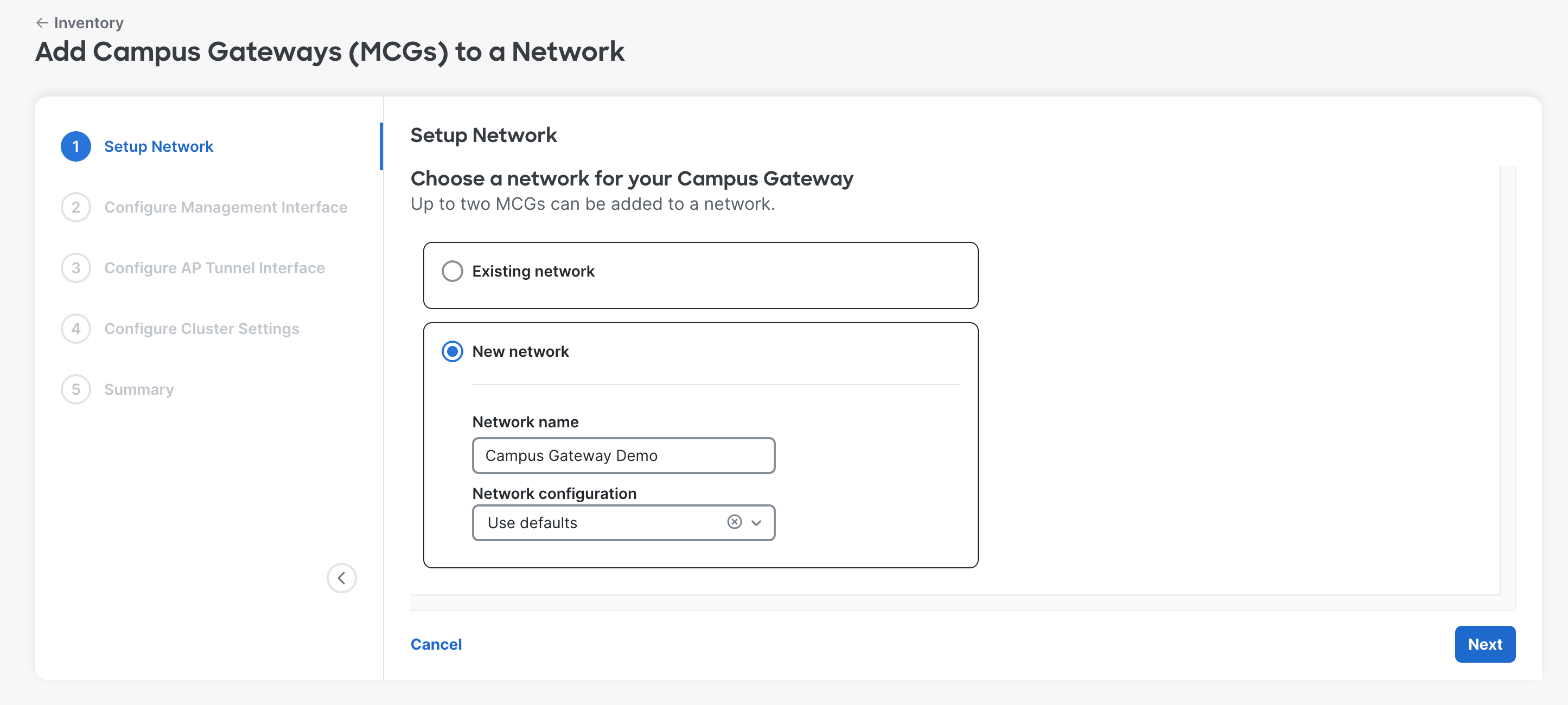
Step 1: In either Network-wide > Configure > Add Devices or Organization > Configure > Inventory, select either a single Campus Gateway or both Campus Gateways and select Add to network. This can be a new network or an existing network.

Adding the Campus Gateway to a network is not supported in the legacy inventory page or legacy licensing page. This is indicated on the page if "View new version" is shown. If using Per-Device Licensing, the Campus Gateway cannot be added to the network regardless of legacy or new version of the pages.

Step 2: Adding a Campus Gateway to a Meraki Network triggers the onboarding flow to add the Campus Gateway to a cluster. The Campus Gateway must be added to an existing network or a new network.
-
Existing Network: Select the existing network name.

All networks will be populated in the existing networks list. The existing network chosen will automatically be configured to include the Wireless and Campus Gateway network type.
- New Network: Input the new network name and select the network configuration to use if needed.
Step 3: Configure the Management and AP Tunnel Interfaces. These are the only two L3 interfaces that can be configured on Campus Gateway.
- Management Interface: Used for communication with Meraki dashboard and building the Meraki Tunnel. Can be assigned an IP via DHCP or static.
- AP Tunnel Interface: Used to terminate VXLAN tunnels from APs and to source traffic to network services (such as RADIUS, syslog). Must be assigned a static IP, as this is the tunnel termination point and cannot change dynamically without causing network disruption.
These can be deployed as:
- Single L3 Interface Deployment: Both the Management and AP Tunnel Interfaces share the same VLAN and IP address. The IP address must be static. This is simpler to deploy as only one VLAN and subnet needs to be configured.
- Dual L3 Interface Deployment: The Management and AP Tunnel Interfaces are separate interfaces on different VLANs and subnets. The Management Interface IP can be static or DHCP. The AP Tunnel Interface must be static. This has the benefit of separating internet/dashboard traffic from internal traffic.
When using Dual L3 Interface Deployment, access points that tunnel to Campus Gateway cannot be in the same VLAN/subnet as the Campus Gateway's management interface. Below is an example of a Static IP configuration.

Configure the Management Interface using DHCP or static assignment. If the AP Tunnel Interface will share the same L3 interface, leave Manually configure AP tunnel interface for this cluster untoggled.

If the AP Tunnel Interface will be a different L3 interface, toggle this option and specify a different VLAN/subnet.

Step 4: Configure the settings for the Campus Gateway cluster.
- Cluster name: Used when referring to and selecting the Campus Gateway cluster to tunnel SSIDs to.
- Uplink port native VLAN: Should match the upstream switch configuration. Untagged received traffic belongs to this VLAN. Traffic sent on this VLAN is sent untagged (without an 802.1Q tag). Accepts one VLAN number. Default is VLAN 1 if left blank. Range: 1-4094, excluding 1002-1005.
- Uplink port client VLANs: Defines the list of VLANs that clients will be assigned and that are allowed on the trunk interface to the upstream switch. Client traffic on VLANs not defined here will be dropped. Accepts multiple VLAN numbers and ranges. Range: 1-4094, excluding 1002-1005.

Step 5: Review the configurations and click Finish to deploy the Campus Gateway to the network.
At first release, cluster deletion is not supported. Once a cluster is created for the network, this cluster must be used for future configurations. To delete a cluster, the network must also be deleted.

Step 6: The Campus Gateway Clusters page displays a list of all Campus Gateways added to the cluster along with the cluster configurations. Once SSIDs are configured to tunnel to the cluster, they will appear in the SSID section.

Step 7: To change the cluster settings, click the Edit button.

A slide-out menu will appear where you can edit:
- Management VLAN and Interface for each Campus Gateway
- AP Tunnel Interface for each Campus Gateway
- Uplink port native VLAN
- Uplink port client VLANs

Removing a Campus Gateway from a Meraki network
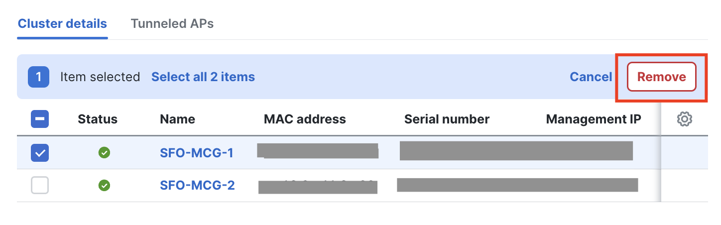
Navigate to Wireless > Campus Gateway (MCG) > Campus Gateways, select the campus gateway(s) you want to remove from the network and click Remove.
If you get an alert stating Deleting all campus gateways from the cluster that is associated with SSID(s) is not allowed, perform these steps before removing the campus gateway device.

Navigate to Wireless > Configure > SSIDs and check which SSIDs are configured to tunnel the traffic to a campus gateway cluster, including disabled SSIDs. In this example, *mcg-psk is tunneling the traffic to the campus gateway cluster SFO-Cluster-1_change.

From the same page, click edit settings, then navigate to Client IP and VLAN and select a different method, such as NAT mode or Bridged, then Save.

Once there are no SSIDs configured as Tunnel mode with Campus Gateway, you can remove the campus gateway from the Meraki network.
Onboarding via the Meraki API
To onboard Campus Gateway via the API:
- Claim the Campus Gateway to the network using the Claim Network Devices API operation.
- Add it to a Campus Gateway cluster using either:
- Create Network Campus Gateway Cluster API operation (for a new cluster), or
- Update Network Campus Gateway Cluster API operation (for an existing cluster)
If the Campus Gateway is only added to the network via the Claim Network Devices API operation without being added to a cluster, it will not appear in the network or the Campus Gateway Cluster page.
Access point to Campus Gateway assignment
When APs are configured to tunnel to Campus Gateway clusters, they receive a list of Campus Gateways from dashboard.
- APs that belong to the same subnet are assigned to the same Campus Gateway.
- Depending on the number of subnets and APs in those subnets, load balancing may not be split evenly between the two Campus Gateways in the cluster.
- APs maintain tunnels to both the primary and backup Campus Gateway.
- For APs in different subnets, the primary and backup Campus Gateway will be different. For example, CG1 is primary and CG2 is backup for AP1, and vice versa for AP2.

If the second Campus Gateway in the cluster is added after the initial deployment (traffic is already being tunneled), the Campus Gateways will form the cluster but will not load balance the APs immediately. APs continue tunneling to the first Campus Gateway until the maintenance window (the same window used for firmware upgrades, defined in Network-wide > General).

How do I monitor which Campus Gateway an AP is tunneling to?
In the Campus Gateway Clusters page, select the Tunneled APs tab. If both the Tunnel status is up (meaning both QUIC and VXLAN tunnels are up between the AP and current Campus Gateway), the Campus Gateway field will show which Campus Gateway the AP is tunneling to.

Redundancy Port
The Redundancy Port (RP) is a dedicated port on the Campus Gateway chassis for syncing client states between chassis. The Campus Gateway has two RP port options:
- 1x 1G RJ45 copper port
- 1x 1G/10G SFP/SFP+ fiber port
Either port can be used for HA. Refer to the Supported SFP Modules section for supported modules.
Do not use both RP ports (RJ-45 and SFP) together. This is not a supported configuration and may lead to unexpected issues.
If the RP link is connected between the Primary and Backup Campus Gateways, they will sync client states over the RP link. Fast keepalives are sent every 100 ms. Keeping the Campus Gateways in sync allows the data path to remain hot with backup tunnels kept alive, enabling failover times of 1-2 seconds if one Campus Gateway fails. Without the RP link, failover time may increase.
RP Link Connection Methods:
- Back-to-Back: The RP port on both Campus Gateways is directly connected with no intermediate switches. This is the recommended method because it is the simplest. The causes of failover would be either a Campus Gateway chassis failure or the RP link failure. The downside is that the maximum distance between Campus Gateways is limited by the SFP/SFP+ module specifications.
- Dedicated L2 VLAN with Intermediate Switches: The RP port on each Campus Gateway is connected to a dedicated port on its respective upstream switch. The connections must share a dedicated L2 VLAN. If the Campus Gateways are in separate data centers, the VLAN must be spanned across the data centers. This method removes the distance limitation but adds deployment complexity.
RP Link Requirements:
|
Parameter |
Requirement |
|
Latency |
< 80 ms |
|
Bandwidth |
> 60 Mbps |
|
MTU |
>= 1500 bytes |
Upgrade software
The first software release version that supports Campus Gateway is MCG 31.2.X and the corresponding AP version will be MR 31.2.X.
- Identical firmware versions: It is mandatory to use the same firmware versions. For example, if the Campus Gateway is updated to MCG 31.2.5, the APs will need to run MR 31.2.5 as well.
- Legacy APs: APs in the same Meraki Network that cannot be upgraded to MR 31.2.X or later (for example, Wi-Fi 5 APs and earlier) will stay on the latest supported code. These APs will not be able to tunnel SSIDs to Campus Gateway.
Upgrade firmware in the Meraki dashboard:
- Where to upgrade: The Campus Gateway and corresponding AP image firmware will be available in the Firmware Upgrades page. Choosing the Campus Gateway image will automatically select the AP image to be upgraded as well.
- Upgrade order: The dashboard will upgrade the Campus Gateway first followed by the AP.

Both options, Minimize upgrade time and Minimize client downtime, are supported for firmware upgrades.
For more information refer to the Managing Firmware Upgrades and Access Point Firmware Upgrade Strategy documentation.
Option 1: minimize upgrade time
Choosing Minimize upgrade time leads to a faster upgrade at the expense of some client downtime. During the upgrade:
-
All Campus Gateways in the cluster upgrade to the new code version at the same time.
-
Once complete, all APs in the network are upgraded at the same time.
Option 2: minimize client downtime
This requires the Campus Gateways to be in a cluster of 2. Standalone Campus Gateway deployments are not supported for this upgrade strategy.
Requirements:
- Campus Gateways must be in a cluster of 2
- Adequate overlapping RF coverage between APs at the site, so if an AP reloads there is still enough RF coverage for clients
Upgrade Process:
- Campus Gateways are upgraded first, followed by APs.
- One Campus Gateway is chosen to upgrade first. All APs tunneling to that Campus Gateway are migrated to the second Campus Gateway. The first Campus Gateway reloads and upgrades.
- After the first Campus Gateway is upgraded, all APs migrate from the second Campus Gateway. The second Campus Gateway reloads and upgrades.
- After both Campus Gateways are upgraded, APs upgrade in a rolling manner, maintaining adequate RF coverage for clients.
For more information on the AP rolling upgrade behavior, refer to: Access Point Firmware Upgrade Strategy
SSID creation
Tunneling to a Campus Gateway Cluster is a per-SSID configuration. For a campus greenfield Meraki deployment, it is expected that all SSIDs will be centrally tunneled. Each AP forms a VXLAN tunnel to the Campus Gateway, which all SSIDs tunneling to a cluster share. This creates an L2 overlay that allows clients to roam seamlessly across all APs in the campus. APs can broadcast both centrally tunneled and locally bridged SSIDs concurrently.
If connectivity between the Campus Gateway(s) and the APs is lost, the centrally tunneled SSIDs will stop broadcasting. Locally bridged SSIDs remain unaffected.

When clients associate to the tunneled SSID, they are mapped to a VLAN defined centrally at the Campus Gateway. The client VLAN is carried to the distribution or core switch, which acts as the default gateway. Because the client VLAN only exists between the Campus Gateway and uplink switch, it can be made as large as needed (for example, /21) since the broadcast domain is confined.
Tunneling supports all SSID configurations:
- Passphrase (WPA2 PSK, WPA3 SAE, and iPSK without RADIUS)
- RADIUS-based (802.1X, MAB, iPSK with RADIUS)
- Open / OWE
- WPN
- Splash Page
Configuring Tunneling for SSIDs:
Step 1: Go to Wireless > Configure > Access Policy and select the SSID to be tunneled.

Step 2: In the Client IP and VLAN section, select External DHCP server assigned and the Tunneled option. Select Tunnel mode with Campus Gateway (MCG) and choose the Campus Gateway cluster created.

If required, enable mDNS gateway here. Refer to the Configure mDNS Gateway Mode section in this guide. Also refer to the Broadcast and multicast traffic suppression section in the Campus Gateway Design and Best Practice Guide for supported mDNS modes and example diagrams.
Step 3: Set the client VLAN in the VLAN tagging section. This can be either the VLAN ID or a Named VLAN. The VLAN configured must be in the list of Uplink port client VLANs configured on the Campus Gateway cluster.

For more information on configuring Named VLANs and VLAN profiles, refer to VLAN Profiles documentation.
If leveraging VLAN override, the VLAN information here can be left untagged.
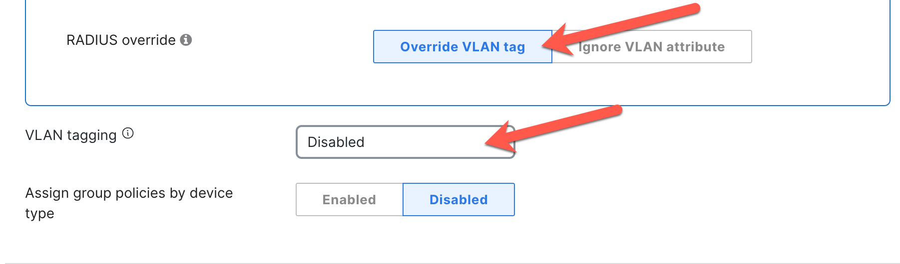
For the following cases, client traffic will be sent out of the Campus Gateway untagged and tagged with the native VLAN configured on the uplink switch port:
- VLAN tagging is disabled (no VLAN assigned)
- VLAN ID is set to 0
- VLAN is set to the Native VLAN of Campus Gateway
If a user configures a VLAN that is not in the list of Uplink port client VLANs at Campus Gateway, the traffic will be dropped.
RADIUS-based SSID and Campus Gateway as a RADIUS proxy
For RADIUS-based SSIDs, Campus Gateway acts as a RADIUS Proxy, optimizing the scale and manageability of large-scale wireless deployments.
In a distributed Cisco cloud-managed deployment, all APs had to be added as a Network Access Server (NAS) to the RADIUS server, potentially requiring hundreds or thousands of devices. By making the Campus Gateway act as a RADIUS proxy, only the IP of the Campus Gateway needs to be added as a NAS, significantly simplifying RADIUS management.
- APs still serve as the authenticator and manage clients' AAA sessions.
- APs send all RADIUS traffic to the Campus Gateway via VXLAN tunnels.
- The Campus Gateway forwards the traffic to the RADIUS server and relays the response to the AP.
- RADIUS servers specified for each SSID are used in order of priority when configured.
- Campus Gateway acts as a RADIUS proxy only for tunneled SSIDs. For locally bridged SSIDs, the AP communicates with the AAA server directly.
AAA traffic is sent via VXLAN tunnel. This allows customers to take packet captures at the AP and analyze the exchange between AP and RADIUS (QUIC is always encrypted).
Change of Authorization (CoA) is supported and can be deployed together with fast and secure roaming (802.11r/OKC).
If you use multiple RADIUS servers and you want to load balance the authentications in a round robin fashion, please contact Meraki Support.
For CoA, ensure the RADIUS server is configured to use UDP port 1700, as Campus Gateway expects CoA packets on this port. CoA requests will be dropped if received on a different port.
Client VLAN Assignment:
When the client associates to APs using 802.1X or any other RADIUS-based authentication, the AP encapsulates the RADIUS messages in VXLAN to send to Campus Gateway. Once AAA returns the VLAN (for example, VLAN 20) in the Access-Accept message to the Campus Gateway, this is forwarded back to the AP.
The AAA server can use the following attributes to return the VLAN name, group, or ID:
- Airespace-Interface Name
- Tunnel-Type (Attr. 64)
- Tunnel-Medium-Type (Attr. 65)
- Tunnel-Private-Group-ID (Attr. 81)
The AP stores the client VLAN and sets it in the VXLAN header when forwarding client traffic. The Campus Gateway then bridges the traffic onto the VLAN.
Note: The VLAN returned by the AAA server must be included in the allowed VLAN list on the Campus Gateway (defined at the cluster level). Otherwise, the traffic will be dropped at the Campus Gateway.
Client VLAN Assignment Priority (descending order):
- Roaming Client (saved VLAN from first association)
- Per-client Group Policy
- Per-device type Group Policy
- RADIUS-assigned VLAN
- SSID-defined VLAN
SSID switching type co-existence

For brownfield Cisco cloud-managed wireless deployments with existing locally switched SSIDs, migration to centralized tunneling at Campus Gateway is expected to happen in phases. The co-existence of locally bridged and centrally tunneled SSIDs is supported on the same APs. Clients can connect to locally bridged SSIDs while other clients connect to centrally tunneled SSIDs at the same time.
Configuring Adaptive Policy
Adaptive Policy is configured per Meraki Network and applied at the AP. Dashboard pushes the configurations for Security Group Tags (SGTs) and Security Group Access Control Lists (SGACLs) to the APs. The APs learn the local clients' SGT via the RADIUS Access-Accept response during client authentication or via static configuration through dashboard.

Upstream (at the AP level): The AP inserts the SGT in the segment ID (SID or policy) in the VXLAN header. The Campus Gateway uses this when bridging the traffic by inserting the received SGT into the CMD header of the 802.1Q packet. The policy is then applied at the destination device (switch or AP).
Downstream (at Campus Gateway): The Campus Gateway reads the SGT from the CMD header and copies it into the SID in the VXLAN header. The policy is applied at the AP. The source SGT is received in the VXLAN header while the destination SGT is known because it belongs to the locally managed client. From there, the SGACL policy is applied.
Enabling Adaptive Policy on Campus Gateway occurs in the following scenarios:
- Campus Gateway is added to a network with Adaptive Policy already enabled
- Adaptive Policy is enabled on a network with Campus Gateway already added
Scenario 1: Campus Gateway is added to a network with Adaptive Policy already enabled
When Campus Gateway is added to a network that already has Adaptive Policy enabled, it will not have the necessary configurations to enable infrastructure Adaptive Policy by default. Specifically, the configs to enable inline SGTs on the Campus Gateway and set the uplink ports to tagged with SGT 2 (the standard infrastructure-to-infrastructure tag) will not be present.
If the uplink switch ports are configured for infrastructure Adaptive Policy, the Campus Gateway will not have connectivity to the network without these configs.
To provide connectivity and enable Adaptive Policy, use one of the following methods:
Method 1: Modifying the Upstream Switch
- Temporarily disable infrastructure Adaptive Policy on the uplink switch ports connected to the Campus Gateway. This allows the Campus Gateway to download its configurations and enable Adaptive Policy on its uplink ports.
- Because Adaptive Policy is disabled on the uplink switch ports, the Campus Gateway will temporarily lose connectivity.
- Re-enable infrastructure Adaptive Policy on the uplink switch ports connected to the Campus Gateway to restore connectivity.
For steps on enabling/disabling infrastructure Adaptive Policy on uplink switch ports, refer to:
- On-Prem managed Catalyst Switches: Deploying Catalyst Switches as the Core of a Meraki Adaptive Policy Switching Network
- Cloud-Managed Catalyst Switches / Meraki MS Switches: Adaptive Policy MS Configuration Guide
Method 2: Using the Local Status Page of Campus Gateway
- Log onto the Local Status Page of the Campus Gateway.
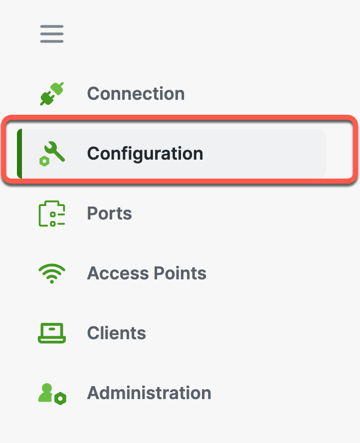
- Go to Configuration and navigate to the Adaptive Policy section.
3. Set the status to Enabled and set the Source Group Tag to match the configuration on the uplink switch port (typically a value of 2 for infrastructure-to-infrastructure communication).

Note: The SGT value can be found in the upstream switch port configurations or, for Cisco cloud-managed devices, in Organization > Adaptive Policy > Groups under Infrastructure.
4. Click Save Changes. The Campus Gateway will gain connectivity to dashboard and download the configurations.

Scenario 2: Adaptive Policy is enabled on a network with Campus Gateway already added
-
Enable Adaptive Policy for the network. For steps, refer to: Adaptive Policy Configuration Guide
-
After enabling, the Campus Gateway will receive the configuration to enable infrastructure Adaptive Policy on its uplink ports.
Note: This may result in the Campus Gateway temporarily losing connectivity. To restore connectivity, configure the uplink switch port to enable infrastructure Adaptive Policy. From this point onwards, the Campus Gateway will stay connected.
Configure mDNS Gateway Mode
Refer to the Broadcast and multicast traffic suppression section in the Campus Gateway Design and Best Practice Guide for supported mDNS modes and example diagrams.
Step 1: Go to Wireless > Configure > Access Policy and select the SSID to be tunneled.
Step 2: In Client IP and VLAN > External DHCP server assigned > Tunneled > Tunnel mode with Campus Gateway (MCG), toggle mDNS gateway to enable.

Step 3: Select all the necessary mDNS services that clients should be able to discover across VLANs.

Post-deployment verification
Monitoring AP tunnel status
In the Campus Gateway Clusters page, select the Tunneled APs tab. If both QUIC and VXLAN tunnels are up between the AP and the current Campus Gateway, the Campus Gateway field will be populated with the Campus Gateway the AP is tunneling to.
Campus Gateway cluster failure detection behavior
Based on the failure type, the amount of downtime will vary.
Access point tunnels down due to network failure
Between the access points and Campus Gateways, regular keepalives are sent for both QUIC and VXLAN tunnels.
QUIC Tunnel:
- Keepalives are sent only if the AP has not received any traffic from the Campus Gateway for 10 seconds.
- Keepalives are then sent in 10-second intervals or until the Campus Gateway sends traffic to the AP (when the connection is idle).
- On keepalive failure, retries occur after probe timeout with exponential back-off until the max idle time is reached (16 seconds).
VXLAN Tunnel:
- Keepalives (BFD echo) are sent every 5 seconds.
- If an echo is missed, four echo retries are sent in 1-second intervals.
- Five missed echos result in 9 seconds of downtime.
If a keepalive failure occurs for one tunnel, both tunnels are brought down. AP tunnel down takes between 9 to 16 seconds to detect the failure event and start a failover.
Campus Gateway chassis failure
In the event of a chassis failure (crash, power down, etc.), stateful and quick failover (less than 1-2 seconds) can only be achieved if the RP is connected between the two Campus Gateways. This allows client states to be synced, keeping the data path hot on the APs' backup Campus Gateway.
- Keepalives are sent every 100 ms.
- A failure event is considered if five RP keepalives and one ping via the AP Tunnel Interface to the other Campus Gateway's AP Tunnel Interface are missed.
- The backup Campus Gateway sends a message to the APs to change the state of their VXLAN tunnel to the backup Campus Gateway from Blocked to Allowed.
- The time for APs to change the VXLAN tunnel state and resume passing client traffic is less than 1-2 seconds.
Campus Gateway network failure
If Campus Gateway loses connectivity to its gateway, the gateway failure detection takes 8 seconds (four consecutive ARP and four consecutive ICMP echos need to be missed). Network failures result in longer detection times and slower failover, leading to longer downtimes.
Campus Gateway cluster high availability behavior
The table below captures the behavior for various scenarios in a cluster deployment.
|
# |
RP Link State |
AP Tunnel Interface Link |
Gateway State at Primary Campus Gateway |
Gateway State at Preferred Backup Campus Gateway |
Action |
|
1 |
UP |
UP |
UP |
UP |
AP joins the primary and preferred backup Campus Gateway. Clients are anchored on the primary. Client records are replicated to the preferred backup. Client state is plumbed to the data plane in the preferred backup and data plane is hot. |
|
2 |
UP |
UP |
UP |
DOWN |
AP joins the primary Campus Gateway. Clients are anchored on the primary. Client records are replicated to the preferred backup. Client states are not plumbed to the data plane in the preferred backup as the AP has not joined it. |
|
3 |
UP |
UP |
DOWN |
UP |
When gateway reachability is lost at the primary Campus Gateway, the preferred backup Campus Gateway notifies the AP. The AP unblocks the VXLAN tunnel with the preferred backup Campus Gateway and GARPs are sent out for the plumbed clients. The AP re-anchors clients to the preferred backup, and clients become active. Gateway reachability failure detection should happen faster than the AP detecting loss of connectivity to the primary Campus Gateway. |
|
4 |
UP |
UP |
DOWN |
DOWN |
AP cannot join the primary or the preferred backup. No client records in either Campus Gateway. |
|
5 |
UP |
DOWN |
UP |
UP |
AP joins the primary and preferred backup Campus Gateway. Clients are anchored on the primary. Client records are replicated to the preferred backup. Client state is plumbed to the data plane in the preferred backup and data plane is hot. Note: Since the AP Tunnel Interface link is down, Dual Master Detection (DMD) is not possible at this time if the RP link goes down. |
|
6 |
UP |
DOWN |
UP |
DOWN |
AP joins the primary Campus Gateway. Clients are anchored on the primary. Client records are replicated to the preferred backup. Client state is not plumbed to the data plane in the preferred backup as the AP has not joined it. Note: Since the AP Tunnel Interface link is down, Dual Primary Detection is not possible at this time if the RP link goes down. |
|
7 |
UP |
DOWN |
DOWN |
UP |
When gateway reachability is lost at the primary Campus Gateway, the preferred backup Campus Gateway notifies the AP. The AP unblocks the VXLAN tunnel with the preferred backup Campus Gateway and GARPs are sent out for plumbed clients. The AP re-anchors clients to the preferred backup and clients become active. Gateway reachability failure detection should happen faster than the AP detecting loss of connectivity to the primary Campus Gateway. Note: Since the AP Tunnel Interface link is down, Dual Primary Detection is not possible at this time if the RP link goes down. |
|
8 |
UP |
DOWN |
DOWN |
DOWN |
AP cannot join the primary or the preferred backup. No client records in either Campus Gateway. |
|
9 |
DOWN |
UP |
UP |
UP |
AP joins the primary and preferred backup Campus Gateway. Clients are anchored on the primary. Client records are not replicated to the preferred backup since the RP link is down. |
|
10 |
DOWN |
UP |
UP |
DOWN |
AP joins the primary Campus Gateway. Clients are anchored on the primary. Client records are not replicated to the preferred backup since the RP link is down. |
|
11 |
DOWN |
UP |
DOWN |
UP |
When gateway reachability is lost at the primary Campus Gateway, the preferred backup Campus Gateway notifies the AP. The AP unblocks the VXLAN tunnel with the preferred backup Campus Gateway. The AP re-anchors clients to the preferred backup and client state is created and plumbed to the data plane (similar to the client joining fresh). |
|
12 |
DOWN |
UP |
DOWN |
DOWN |
AP cannot join the primary or the preferred backup. No client records in either Campus Gateway. |
|
13 |
DOWN |
DOWN |
UP |
UP |
Double fault. Since the Campus Gateways cannot communicate with each other, each node assumes the other is down. But the AP will be able to connect to the primary as well as the preferred backup. The AP may anchor the clients on the primary, but there will be no replication of records to the preferred backup. Note: When both the RP and AP Tunnel Interface links go down, the Campus Gateway will send a Peer Node Down event to the AP. The AP may see a conflict (Peer Node Down event, yet its QUIC tunnel with the primary is UP). |
|
14 |
DOWN |
DOWN |
UP |
DOWN |
Double fault. Since the Campus Gateways cannot communicate with each other, each node assumes the other is down. But the AP will be able to connect to the primary. The AP anchors the clients on the primary, but there will be no replication of records to the preferred backup. |
|
15 |
DOWN |
DOWN |
DOWN |
UP |
Double fault. Since the Campus Gateways cannot communicate with each other, each node assumes the other is down. But the AP will be able to connect to the preferred backup. The AP anchors the clients on the preferred backup. Note: When both the RP and AP Tunnel Interface links go down, the Campus Gateway will send a Peer Node Down event to the AP. |
|
16 |
DOWN |
DOWN |
DOWN |
DOWN |
AP cannot join the primary or the preferred backup. No client records in either Campus Gateway. |
Troubleshooting
Connecting to the Local Status Page
If connectivity between Campus Gateway and dashboard is lost or cannot be established, the Local Status Page (LSP) can be used to manually configure parameters such as the uplink port VLAN, IP address, or DNS settings to restore connectivity.
Common reasons for connectivity issues:
- DHCP is not available on the active VLAN
- Information provided by DHCP is incorrect (missing DNS, wrong default gateway, etc.)
- Connectivity to Meraki dashboard is not available
There is no console access on Campus Gateway, so the LSP is the primary tool for out-of-band uplink configuration and overall system health checks.
If Campus Gateway is unable to reach dashboard even after using LSP, contact Meraki Support.

Method 1: directly connecting via the Service Port
Step 1: Plug a computer into the Service Port (SP port). The computer will be assigned an IP address in the range 198.18.0.X.
Refer to the Front View section of the hardware documentation for the location of the SP port.
Step 2: Navigate to https://mcg.meraki.com or directly to https://198.18.0.1 and enter the credentials.
Default Credentials (for Campus Gateways that have never connected to a Meraki network or have been factory reset):
- Username: admin
- Password: Cloud ID (Meraki Serial Number) of the Campus Gateway
Note: The Cloud ID can be found in the shipment email from Cisco and physically on the chassis of the Campus Gateway.
After the Campus Gateway connects for the first time to a Meraki network, LSP credentials are automatically updated to a strong password. Please see the Changing Log-In Credentials section in the Using the Cisco Meraki Device Local Status Page guide for more details.
It is highly recommended to set a the LSP password as Meraki Support has no visibility into the generated password. If there is a connectivity issue with the Campus Gateway and dashboard and the LSP cannot be accessed due to the password, Meraki Support will need to be contacted to factory reset the appliance.
Method 2: connecting via the Management or AP Tunnel Interface
Step 1: Navigate to the IP address of the Management or AP Tunnel Interface of Campus Gateway. For example, if the AP Tunnel Interface uses the IP address 10.70.2.2, access the LSP at https://10.70.2.2.
Default Credentials: Same as Method 1 (admin / Cloud ID).
After the first connection to a Meraki network, credentials are automatically updated. See the Using the Cisco Meraki Device Local Status Page guide for details.
Note: After deploying Campus Gateway in a cluster, the LSP can be accessed using the IP address of the Management or AP Tunnel Interface of Campus Gateway.
Local Status Page features
Health summary

The LSP home page provides an overview of key Campus Gateway components:
- Dashboard Connectivity: View the connection status to dashboard
- Campus Gateway Details: Key information such as Meraki Network, Campus Gateway chassis name, and MAC Address
- Client Connection: IP address of the client used to access the LSP
- Device Summary: Total number of APs tunneling to the Campus Gateway and the number of connected clients
- System Resources: CPU and memory utilization, chassis temperature, and power supply status
Uplink configuration
Configure the following uplink settings:
- VLAN
- IP Address
- Gateway
- DNS server(s)

The Campus Gateway uses these settings to connect to dashboard if DHCP is not available or not configured. Since all ports are configured in a single L2 port-channel, this configures the L3 VLAN interface (SVI) for management connectivity.
If Campus Gateway is already provisioned using the single interface deployment (where both Management and AP Tunnel Interface share the same IP address), the Uplink Configuration cannot be changed through LSP, as this would also change the AP Tunnel Interface and cause wireless network downtime.

Adaptive Policy (via LSP)
If Adaptive Policy is configured in the network and Campus Gateway is unable to connect to the upstream network and dashboard because the uplink port is not configured with the correct SGT, the LSP can be used to enable uplink traffic to be tagged with the correct SGT (typically a value of 2).

The SGT value can be found in the upstream switch port configurations or, for Cisco cloud-managed devices, in Organization > Adaptive Policy > Groups under Infrastructure.
Switchport details
View the Admin and Operational status of all ports and their VLAN configurations. Use this to verify the configuration pushed from Meraki dashboard.

Access Points page
View the list of all APs tunneling to the Campus Gateway, along with their MAC and IP addresses.

Clients page
View all clients connected to centralized SSIDs, including the SSIDs and VLANs they are connected to. Any state other than "Run" for client state indicates a connectivity issue.

Support Bundle creation
If issues occur on the Campus Gateway, Meraki Support may request a support bundle for debugging.
Step 1: Click Generate to begin the Support Bundle creation process. This takes a few minutes to complete.
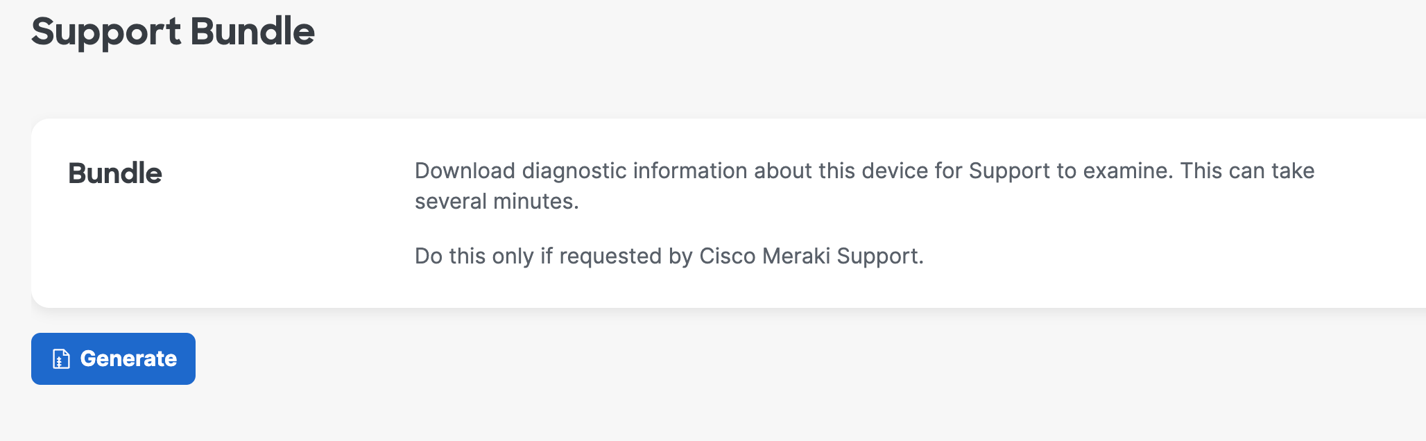
Step 2: Once completed, click Download to get the generated tar.gz file and share it with Meraki Support.


Reset and reload the Campus Gateway
The Campus Gateway can be reloaded or factory reset using the LSP. Click the respective button on the LSP page.
