
Meraki WiFi in a Box Design Guide (CVD)
Overview
The purpose of this document is to explain how to design and implement an Enterprise Wireless LAN solution based on Cisco Meraki MR Access Points in addition to a Cloud Radius Server and a Cloud Identity Store. This solution serves customers looking for a WiFi in a box solution without any on-prem components but yet provides secure access to Wireless LAN as well as workloads in AWS.
Solution Overview
Enterprise customers require secure access to Corporate WiFi that usually relies on an enterprise authentication server such as Radius server, which in most cases is integrated with an Active Directory as an identity store. As customers move their workloads to the Public Cloud, they are also looking to do the same with their Corporate IT platform(s) to be able to scale and meet continuously changing business challenges. This will also help them to rapidly deploy network access and control services anywhere. (e.g. Teleworkers, Hybrid Workspaces, etc)
The WiFi in a box solution relies on Meraki MR Access Points for providing enterprise-grade Wireless LAN whilst integrating with Cisco ISE deployed in AWS and Azure Active Directory. Clients will be authenticated using EAP-TTLS with the Cisco ISE performing identity lookups on Azure Active Directory using REST ID with ROPC (HTTPS).
.png?revision=1)
The above diagram illustrates the solution in high level. The main components/features are:
- vMXs in AWS Configured as Concentrators
- Cisco ISE 3.1 used for 802.1X authentication and posturing (Corp, Guest, BYOD)
- Azure AD as an identity server
- MR Access Points for Wireless LAN access(1)
(1) MR Access Points will be configured with SSID(s) in Teleworker VPN mode
Optionally, the following components can also be used to extend the above solution:
- Z3 Teleworker Gateways configured with Site-to-Site VPN (For Teleworkers and Home Users)
- MX Security & SD-WAN Appliances for S/M/L Branches
Please note that the Teleworker VPN mode is suitable for connecting small branches, Teleworkers and Home users (Up to 5 users per AP) to a MX/vMX concentrator. For larger branches, it is recommended to deploy a local MX with site-to-site VPN and configure the MR SSIDs in Bridge mode. Nonetheless, if high availability is required on the VPN Concentrators (e.g. use of a secondary VPN concentrator) it will be also required to use a local MX on-site with site-to-site VPN and leverage multiple head-ends for resiliency.
Key Benefits
- Ease and speed of deployment
- Head-end Scalability (Scale up or down your vMX instances)
- Consistent end-user experience regardless of their location (e.g. Hybrid Workplaces)
- Endpoint flexibility (MR/MX/Z3)
- Secure Access to AWS Workloads
- High Availability
- Local Breakout
- End to end automation
Solution Use Cases
- Secure Corporate Wireless LAN Access with AD authentication
- Hybrid Workplaces (e.g. Home Workers)
- BYOD
Solution Pre-requisites
- AWS account
- vMX license
- ISE instance (v3.1)
- Azure AD
- MR Access Points, MX Security & SD-WAN Appliance or Z3 Teleworker Gateway + License(s)
Solution Design
For the purpose of this CVD, we will consider the following sample topology:
Sample Topology
.png?revision=1)
Traffic Flow
- User Connects to a broadcasted SSID that is configured with WPA2-Enterprise
- The MR Access Point encapsulates the traffic in an AutoVPN Tunnel towards the vMX in AWS
- The vMX terminates the tunnel and initiates the Radius request to the designated Radius Server (Cisco ISE 3.1 that resides in AWS as well)
- The Cisco ISE server performs a HTTPS REST ID OAuth request with ROPC
- User admitted on network
The following diagram explains the traffic flow:
.png?revision=1)
For more information about using Cisco ISE 3.0/3.1 REST ID with Azure Active Directory, please refer to the following document.
vMX Design Guidelines
The following section explains the design guidelines before deploying a vMX instance in the AWS Cloud.
vMX Sizing Principles
VPN Tunnels
The first step is to determine the number of tunnels required for your solution. Please note that each AP in your dashboard will establish a L2 VPN tunnel to the vMX per configured SSID.
Example:
An Organization with 100 APs all configured with the following settings:
- SSID#1: Bridge mode
- SSID#2: Teleworker mode
- SSID#3: Teleworker mode
- SSID#4: NAT mode
Thus the number of tunnels in this case should be 200 (100 APs * 2 SSIDs) VPN tunnels terminating on the vMX.
Please note that MR Access Points will establish a tunnel per configured tunnel SSID regardless of it being broadcasted or not (enabled/disabled), and regardless of it being tagged to the AP or not (SSID Availability)
In case of other tunnel types, please refer to the following sizing guidelines:
| Tunnel From | No of Tunnels | Notes |
| MR Access Points | Tunnel per AP per SSID | Each configured SSID will form a L2 VPN Tunnel |
| MX Security & SDWAN Appliance | Tunnel per local uplink | Each local uplink on the MX will form a L3 VPN Tunnel |
| ClientVPN | Tunnel per remote user | Each ClientVPN will form a L2TP VPN Tunnel |
| Non-Meraki VPN | Tunnel per Peer per Subnet | Each subnet reachable via the Non-Meraki Peer should be counted as a Tunnel |
Tunnel Sizing Example
An Organization with the following:
- 5 x Small Branches each with 2 APs, each AP with a single tunnelled SSID
- 20 x Large Branches each with a local MX, and each MX has dual uplinks
- 50 x ClientVPNs
- 1 x Non-Meraki VPN Peer with 3 remote subnets
The total number of Tunnels on the VPN Concentrator in this case would be:
5 (Small Branches) * 2 (APs) * 1 (SSID) + 20 (Large Branches) * 2 (Uplinks) + 50 (ClientVPN) + 1 (Non-Meraki VPN Peer) * 3 (Remote subnets) = 103 tunnels in total.
Please refer to the latest MX Sizing guide for the recommended number of tunnels per vMX instance. Please note that you need to account for all tunnels terminating on the same instance (MX Tunnels, MR Tunnels, ClientVPN Tunnels, Non-Meraki VPN Tunnels) where applicable
VPN Throughput
The second step is to determine the throughput required on the vMX. Capacity planning in this case depends on the traffic flow (e.g. Split Tunneling vs Full Tunneling) and number of sites/devices/users Tunneling to the vMX.
Please note that VPN Throughput sizing is to account for the client data plane traffic in case it needs access to AWS resources sitting behind the vMX
Capacity Sizing Example
Following on the previous mentioned example above:
- 5 x Small Branches and each SSID generating around 10Mbps (Split Tunnelling)
- 20 x Large Branches each with dual uplinks each 50Mbps bandwidth. And assuming 80% local breakout (Split Tunnelling, with 20% of the traffic to AWS workloads)
- 50 x ClientVPN users each generating around 5Mbps (Access to AWS workloads)
- 1 x Non-Meraki VPN Peer generating around 1Mbps (Terminating on the same vMX)
The total throughput on the VPN Concentrator in this case would be:
5 (Small Branches) * 2 (APs) * 10Mbps + 20 (Large Branches) * 100Mbps * 20% (Split tunneling) + 50 (ClientVPN) * 5Mbps + 1 (Non-Meraki VPN) * 1Mbps = 751Mbps in total.
Please refer to the latest MX Sizing guide for the maximum supported throughput per vMX instance. Please note that you need to account for all traffic traversing the same instance (Site-to-site traffic, SSID traffic, ClientVPN traffic, Non-Meraki VPN traffic) where applicable
All vMX SKUs are supported in AWS (S/M/L)
Solution Deployment
vMX Deployment Mode
MX concentrators can be deployed in either Routed mode or One-armed mode. Please refer to the following article for more information on the VPN Concentrator Deployment.
Though both Routed mode and One-armed Concentrator mode support SSID Tunneling, it is recommended in this use case to deploy the VPN Concentrator in Routed mode since Broadcast traffic is not allowed in AWS which impacts DHCP at the head-end. However, please note that the IP Functions (e.g. Authentication traffic, Client traffic, etc) will egress from the VPN Concentrator WAN Interface NAT'd. For further information, please refer to the following article. On the other hand, this will simplify the configuration on ISE as you will only need one network device configured as an authenticator for all supplicants (in this case, the vMX) regardless of how many remote MR Access Points are deployed.
For the purpose of this CVD, the vMX in AWS will be deployed in Routed mode. If this option is not visible on dashboard, please contact Meraki Support to have it enabled.
vMX Setup in AWS
The following section summarizes the steps required to deploy a vMX in AWS. For full details please refer to the implementation guide.
Dashboard Configuration
- Navigate to Organization > Configure > License info to add the vMX license to your network (If you haven't done so already) or ensure that you have a valid vMX license in our dashboard
- Create a dashboard network with Name: AWS, type: Security appliance and Network configuration: Default Meraki Configuration (Or clone from an existing network where applicable).

- Assign a vMX to your network
- Verify that the firmware configured for your network is MX 15.37+
- Navigate to Security & SD-WAN > Configure > Addressing & VLANs, and choose Routed mode (Please contact Meraki Support to enable this if you don't see that option on dashboard)

- Enable VLANs under LAN Settings
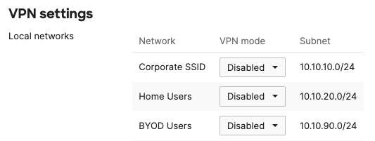
- Create multiple VLANs to concentrate your SSIDs' traffic (e.g. VLAN 10, VLAN 20 & VLAN 90 per the sample topology above)

- Navigate to Security & SD-WAN > Configure > Site-to-site VPN and turn on VPN with this vMX being a Hub (Mesh)

- Keep VPN Turned off for all configured VLANs
- Navigate to Network-wide > Configure > General and choose the time-zone for your vMX network

- Navigate to Security & SD-WAN > Monitor > Appliance status and click on the edit button next to the Appliance name and change the name as desired (e.g. vMX-AWS)
- Click on Generate an authentication token and save it
Please note that the authentication token will be valid for an hour. It has to be claimed in AWS within the hour otherwise a new authentication token must be generated as described above
Concentrator Resiliency - Optional
In order to improve service availability, customers can deploy a secondary vMX concentrator in AWS for resiliency purposes. This allows for tunnels from the MR access points to failover to a secondary vMX in the event that the primary is unreachable for any reason. To do that, simply repeat steps 1-12 in the previous section to create a second network and claim a vMX license into that network.
Each vMX must be in its own dashboard network. Please note that this is NOT a warm-spare configuration.
Please refer to the following diagram for more details:
.png?revision=1)
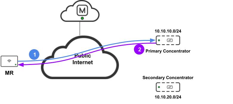
The above diagram shows the tunnels for the Corporate SSID. Remember, the Access Point will form a tunnel per configured SSID with tunneling to each configured concentrator.
Please note that deploying a secondary concentrator requires an additional license in Meraki dashboard. It is recommended that both vMXs are of the same size (e.g. vMX-L)
After completing the above steps, there is an additional step to complete the configured required for having a secondary concentrator in this solution.
Given that the Meraki Access Point will form tunnels to each configured concentrator, it needs to perform health checks to maintain the tunnel status and failover in between as required. Meraki uses DHCP to perform these health checks. To understand how that works, please refer to the following diagram:
- The Access Point sends a DHCP request (in-tunnel) tagged with the VLAN configured requesting the configured IP address (aka dhcpheartbeat) to the primary concentrator at the frequency of the configured Hello interval (Please refer to this section)
- The primary concentrator responds with a DHCP response
- The Access Point marks the tunnel UP
However, if the Access Point does not receive a DHCP response it will switch to the secondary concentrator and perform the health checks as shown in the following diagram:
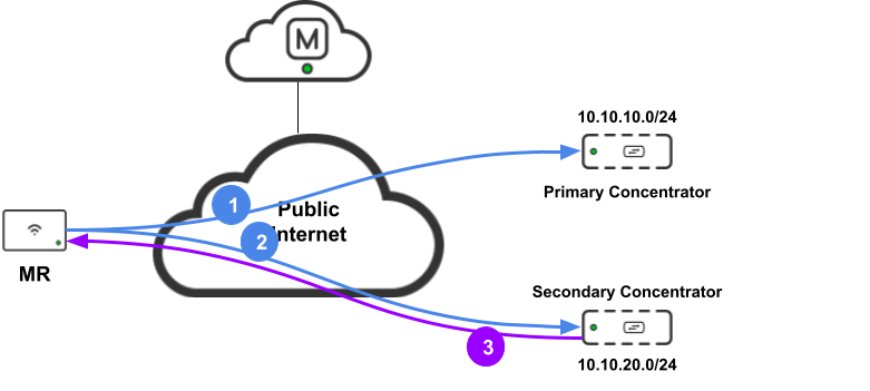
- The Access Point sends a DHCP request (in-tunnel) tagged with the VLAN configured requesting the configured IP address (aka dhcpheartbeat) to the primary concentrator but receives no DHCP response
- After the tunnel idle timeout, the Access Point will switch to checking the status of the tunnel to the secondary concentrator by sending a DHCP request (in-tunnel) tagged with the VLAN configured requested the configured IP address (aka dhcpheartbeat) to the secondary concentrator
- The secondary concentrator responds with a DHCP response
- The Access Point marks the tunnel to the secondary concentrator UP
The dhcpheartbeat requested IP address will be sourced with the AP's MAC address. To ensure that the vMX replies with a DHCP Ack, we will configure that under the DHCP configuration section:
- Navigate to Security & SD-WAN > Configure > DHCP
- Under each DHCP scope, configure a fixed IP assignement with the following parameters:
- Client name = dhcpheartbeat
- MAC address = MAC address of one of your APs
- LAN IP = A reserved IP address for the purposes of tunnel health check (e.g. 10.10.10.2 for VLAN 10, 10.10.90.2 for VLAN 90, etc.)
- Repeat Step 2 for all Access Points in your network that are configured with SSID tunneling (i.e. Each entry with unique MAC address and IP address)
- Click Save
- Repeat steps 1-4 for your secondary concentrator (i.e. Navigate to it's network in dashboard)
Please refer to the following diagram as an illustration:

AWS vMX EC2 Setup
- Go to the AWS Market Place to access the AMI by clicking here
- Select the EC2 instance type (The recommended instance type for vMX-S and vMX-M is c5.large. For vMX-L c5.xlarge should be used)
- Select the region to launch the EC2 instance in (This should match the availability zone your VPC resides in)
- Select 64-bit (x86) Amazon Machine Image (AMI) as the fulfillment option
- Click on Continue to Subscribe button (Please allow a few minutes for the subscription to be activated)
- Once your subscription is available, Click on Continue to Configuration
- You might be prompted to confirm the fulfillment and region options
- Click on Continue to Launch
- For "Choose action" option select the "Launch through EC2" and click Launch.
- Choose the EC2 instance type (The recommended instance type for vMX-S and vMX-M is c5.large. For vMX-L c5.xlarge should be used)
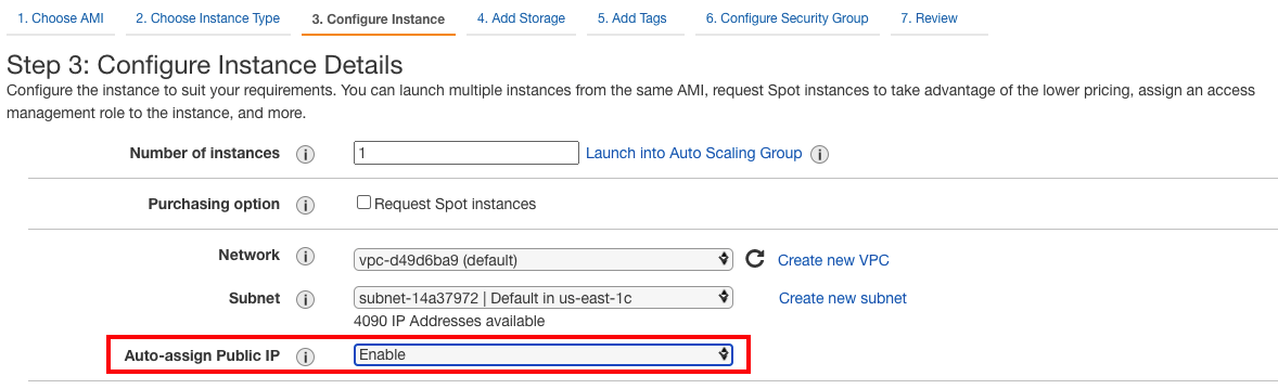
- Click Next: Configure Instance Details
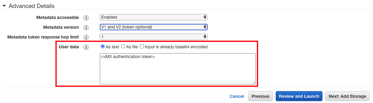
- Select the VPC and the subnet the instance will be a part of and make sure the "auto-assign public IP" is Enabled.
- Under "Advanced Details" enter the vMX authentication token from the dashboard in the user data field. (Remember the token is only valid for an hour).
- Click on the Configure Security Group tab, and choose the following:
- Create a new Security Group
- Security Group name: Choose a name
- Description: Choose a description
- Change existing rule to type: All traffic and description: Allow all
- Click Review and Launch to finish creating the instance (It may take several minutes before the software subscription completes and the instance launches)
- Select or create a new key pair and click continue
- Select the instance that you have just created
- Click on the Networking Tab
- Expand Network interfaces
- Click on the network interface
- From the Actions tab, click on Change Source/Dest. Check
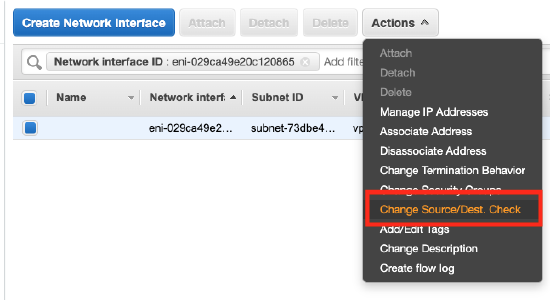
- Disable the Source/destination check for the network interface and click Save

At this stage, you should be able to verify that the vMX is online on Meraki dashboard by navigating to the AWS network then Security & SD-WAN > Monitor > Appliance status.

Deploying a Secondary Concentrator with EC2 - Optional
If you are deploying a secondary concentrator for resiliency as explained in the earlier section, there are some guidelines that you need to follow for the deployment to be successful:
- Without using an AWS Transit Gateway, The two vMX instances and the ISE instances all must be in the same AWS region
- It is recommended that both vMXs be of the same size (e.g. c5.xlarge)
- The vMXs must be in separate networks in the Meraki dashboard
- When tested for the purpose of this CVD, both vMXs were using the same security group
To deploy a secondary concentrator first you need to create a second instance (aka EC2) please repeat steps 1-22.
Please choose the same region that you have used with the first vMX instance to ensure that traffic can route between the vMXs and the ISE instance
By now, your second vMX should be online in the Meraki dashboard.

Navigating to Organization > Monitor > Overview should show you the status of both vMX appliances:

For the correct operation of your vMXs, please make sure that the routing table associated with the VPC hosting them has a route to the internet (i.e. includes an internet gateway attached to it)
In your AWS console, navigating to EC2 > Instances should show you the status of both instances:

In your AWS console, navigating to VPC > Route table should show you the routes in the route table attached to your VPC:

Please note that the above Route table is just an example. Please add the routes appropriate for your deployment
Azure AD Setup
The following section describes the steps needed to setup an Azure Active Directory. For more information, please refer to the following documentation.
- Login to your Azure Portal by clicking here
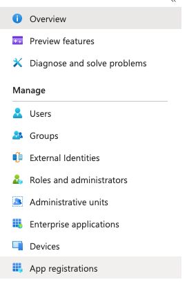
- From the Azure services section, click on Azure Active Directory

- From the left pane menu, Click on App Registrations
- From the top tab menu, Click on New Registration
- Choose a name for this application, and a suitable option for the account type (e.g. single tenant)
- Click on Register

- Click on the application that you have just created

- Copy the Application (client) ID and save it
- Copy the Directory (Tenant) ID and save it

- From the left pane menu, Click on Authentication
- Under "Allow public client flows", please select Yes

- Click Save
- From the left pane menu, Click on Certificates & secrets
- Click on New client secret
- Choose a description and an expiry (e.g. 12 months)
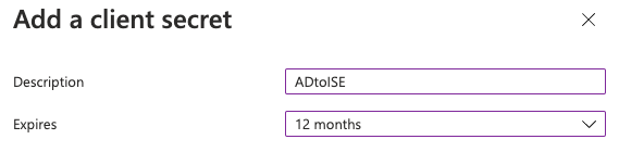
- Click Add
- Once the secret has been created, Copy the Value and the Secret ID and save them (You won't be able to retrieve this later so remember to save it!)
- From the left pane menu, Click on Token configuration
- Click on Add groups claim
- From the right side menu, Select Security Groups
- Expand the ID section, and select Group ID
- Expand the Access section, and select Group ID
- Click Save

- From the left pane menu, Click on API permissions
- Click on Add a permission and select Microsoft Graph
- Click on Application permissions and in the search field type in "group" then expand the Group section
- Select "Group.Read.All" then Click on Add permissions
- Click on Grant admin consent for <Directory Name> then Click Yes and the status should turn green

- From the top left corner, Click on Home then click on Azure Active Directory
- From the left pane menu, Click on Groups
- Create Groups for your organization (see example below) by clicking on New Group

- Click Create

- From the top left corner, Click on <Directory Name>
- From the left pane menu, Click on Users
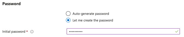
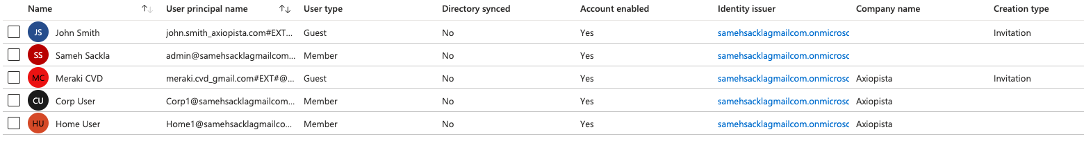
- From the top tab menu, Click on New User (Please note that it's up to you on how you want to add users to your Azure AD, this is just an example) and fill all relevant details as shown below:

 .
. 
- Now you should have users created on Azure AD
- Please note that you will have to login once (username can be retrieved by clicking on any of the users listed above and password is the one your specified when you created the user) to change the password to avoid any issues later on.
Now your Azure AD is setup and ready for the Cisco ISE integration.
Deploying Cisco ISE in AWS
The following sections will explain the steps needed to deploy Cisco ISE 3.1 in AWS. For more information about v3.1, please check the following documentation. And for 3.1 release notes, please check this link.
Create a Key Pair
- Login to your AWS Console as a root user (not IAM user) of your account
- Verify or choose your region from the drop-down menu next to your name
- Open the services menu and choose Compute > EC2
- From the left menu choose Network & Security > Key Pairs
- Click on Create Key Pair
- Fill using the following attributes:
- Name: ISE-AWS (or any other name of your choice)
- Key Pair Type: RSA
- Private Key File Format: .pem
- Click again on Create Key Pair
- When prompted, save the ISE-AWS.pem private key file in a folder
- If you are using MacOS or Linux change the file permissions so it cannot be viewed by others or accidentally overwritten or deleted by you:
chmod 400 <folder/file-name>.pem
Do not lose this private key file! You will not be able to login to your AWS EC2 instances configured with the corresponding public key.
When you create instances in AWS, you may choose to put the matching public key into your VMs to authorize your SSH login. To use your key with AWS EC2 instances, you will connect using SSH and authenticate with the -i identity file option which is your CloudISE.pem private key:
ssh -i ~/.ssh/CloudISE.pem admin@{hostname | IP}
AWS EC2 ISE instance Setup
Please note that this design guide will follow the Marketplace approach to launch Cisco ISE CFT. For more information about CFT, please refer to the following document CloudFormation template.
For more information about AWS EC2 instance sizing for Cisco ISE, please refer to the following document. We will be using c5.4xlarge to deploy Cisco ISE 3.1 as described in the following sections.
- Login to your AWS console and access the Marketplace from here
- Choose your region and fulfilment mode 64-bit (x86) Amazon Machine Image
- Select Continue to Subscribe. Please wait for a few moments whilst the subscription becomes available.
- Click on Continue to Configuration
- In the Configure this Software section, Choose the following:
- Fulfilment option: CloudFormation Template and choose a suitable template from the next drop down menu
- Software version: 3.1 (Aug 12, 2021)
- Region: Choose the region where your vMX resides
- Click on Continue to Launch
- In the Launch this Software section, and under Choose Action, choose Launch CloudFormation
- Click Launch
- In the Create Stack section, for Prepare Template select Template is ready, and for Template source select Amazon S3 URL
- Click Next
- In the next section, please fill the following parameters:
- Stack name: A name of your choice
- Hostname: A hostname of your choice (This field only supports alphanumeric characters and hyphen (-). The length of the hostname should not exceed 19 characters)
- Instance Key Pair: Choose the key that you have created in the previous section
- Management Security Group: Choose the Security Group created when you launched the vMX in AWS
- Management Network: Choose the subnet that your vMX resides in (e.g. 172.31.16.31)
- Management Private IP: Choose an IP of your choice within the selected Management Network Subnet
- Time Zone: Choose your time-zone
- Instance Type: c5.4xlarge (Or a suitable type based on your sizing requirements)
- EBS Encryption: True
- Volume size: 600 (Recommended for production)
- DNS Domain: Enter a domain name
- Name Server: Enter a DNS server that you wish to use (e.g. 208.67.220.220 / 208.67.222.222)
- NTP Server: Enter a NTP server that you wish to use
- ERS: yes
- OpenAPI: yes
- pxGrid: no (Unless it's required for your deployment)
- pxGrid Cloud: no (Unless it's required for your deployment)
- User details: Choose a compatible password and confirm it


- Click Next
- Click Next
- Click Launch Stack
At this stage, your ISE instance should be up and running. You can verify that by going to your EC2 Dashboard, then instances, and click on your ISE instance.That will expand the instance details and show you the Public IP address of the ISE instance. Click on it to open the web interface of your ISE instance:

The web interface should look like this:

You can login using:
Username: admin
Password: <The password that you have specified on step 11 in the previous section>
ISE ROPC Configuration
This section explains the steps needed to integrate Cisco ISE with Azure AD using ROPC (EAP-TTLS) method.
Before proceeding with this section, please verify that the REST Auth Service is running on Cisco ISE by using SSH login and running the following command:
To SSH to your AWS ISE instance, use the public IP and the following command (Mac,Linux):
ssh -i "<Folder/File-name>.pem"admin@<Public IP of your ISE instance>
show application status ise
ISE-AWS/admin# show application status ise


ISE PROCESS NAME                       STATE            PROCESS ID
--------------------------------------------------------------------
Database Listener                      running          32486
Database Server                        running          129 PROCESSES
Application Server                     running          45061
Profiler Database                      running          37569
ISE Indexing Engine                    running          46031
AD Connector                           running          46996
M&T Session Database                   running          37345
M&T Log Processor                      running          45297
Certificate Authority Service          running          23275
EST Service                            running          73725
SXP Engine Service                     disabled
TC-NAC Service                         disabled
PassiveID WMI Service                  disabled
PassiveID Syslog Service               disabled
PassiveID API Service                  disabled
PassiveID Agent Service                disabled
PassiveID Endpoint Service             disabled
PassiveID SPAN Service                 disabled
DHCP Server (dhcpd)                    disabled
DNS Server (named)                     disabled
ISE Messaging Service                  running          24504
ISE API Gateway Database Service       running          36128
ISE API Gateway Service                running          42163
Segmentation Policy Service            disabled
REST Auth Service                      running          175770
SSE Connector                          disabled
Hermes (pxGrid Cloud Agent)            disabled


ISE-AWS/admin#
Please note that you wont be able to SSH to your AWS instance without changing the .pem file permissions (This has been created with the "Create a Key Pair" section above).
To change the file permissions on a Mac or Linux, you can use the following command:
chmod 400 <folder/file-name>.pem
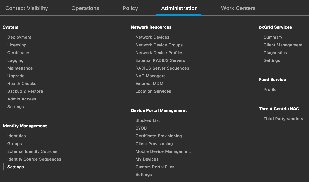
If the service is not running, please go back to your Cisco ISE web interface and Click on top left corner to access the full menu, then Click on Administration then under Identity Management Click on Settings. From there and on the left pane menu, Click on Rest ID Store Settings and make sure it is Enabled.

Once the REST Auth Service is running on ISE, you can proceed with the next steps.
ISE External Identity Sources Configuration
- Login to your ISE instance in AWS (Public IP can be retrieved from your AWS instance) using the credentials previously created during the setup process (Step 11 in the previous section)
- Click on the top left corner to access the full menu, then Click on Administration then under Identity Management Click on External Identity Sources

- From the left pane menu, Click on REST (ROPC) and then Click Add
- Here you will need to provide the Client ID, Tenant ID and Secret Value. (These were created in Step 16 of "Azure AD Setup" section above and you should have saved them before moving to Step 17 as you cannot go back and retrieve them)
- Under Username Suffix, that should be the Identity Issuer found on your Azure AD with the @ before it

- Once you have filled the details above, Click on Test Connection. That should come back successful

- Click on Groups, then Load Groups, That should pull the groups that you have already configured on Azure AD and add the groups that require access
- Click on Save

ISE Policy Sets Configuration
This section explains the steps needed to configure policy sets on Cisco ISE for the purpose of this design.
- Click on the top left corner to access the full menu, then Click on Policy then under Policy Elements Click on Conditions
- Click on the Protocol icon and then on the right hand side Click on Protocol icon again and search for EapTunnel
- Add a condition EQUALS EAP-TTLS

- Click Save
- Then, save this a new library condition and give this condition a name such as EAP-TTLS
- Click on the top left corner to access the full menu, then Click on Policy then Click on Policy Sets
- There you should find the "Default" Policy. Click on the settings wheel to "insert new row above"
- Give your new policy a name (e.g. Corporate) then click on the + sign to start adding conditions
- In this section you need to filter for devices that should match this policy (e.g. Corporate WiFi devices, etc). Please check the below example but follow your own requirements to create this policy set.
- Now Click on the arrow on the right-hand side of your policy to expand the policy authentication and authorization details
- Click on Authentication Policy. You should find the default policy there. Click on the settings wheel to "insert new row above"
- Give your policy a name (e.g. Azure) and then click on the + sign to add a condition
- Click on the Protocol icon on the left hand side and you should find EAP-TTLS condition that you have created earlier
- Drag and drop the EAP-TTLS condition to the right hand side

- Click on Use
- On the right hand side of your authorization policy, Under Use search for the external identity source (AzureAD) that you have created previously.

- Adjust the policy options as needed
- Click on Authorization Policy
- Here you can add policies for your AD groups as appropriate. Please refer to the below example:

- Click on Save
Please note that the policy configuration above is just an example. You should configure the policies required for your environment as appropriate.
ISE Network Device Configuration
This section explains the steps needed to add the vMX as a network device on Cisco ISE (Please note that since we are using Teleworker VPN mode on the MR access points, the MX in this case is acting as the authenticator on behalf of the Access Point)
- Click on the top left corner to access the full menu, then Click on Administration then Network devices
- Click on Add
- Add the vMX with the following details:
- Name = <choose a name> (e.g. MR-via-vMX)
- Description = <choose a description>
- IP address = <vMX WAN uplink Private IP address> (172.31.16.239/32 per the topology above. This can be found either in your AWS EC2 dashboard or on the Meraki dashboard network with the vMX from Security & SD-WAN > Monitor > Appliance status > then click on Uplink

- Device Profile = Cisco
- Model name = MR
- Radius secret = <choose a Radius secret>

- Click Save
Please note that if you are using MX appliances onsite then you will need to add each MR as a Network Device on Cisco ISE. The above configuration reflects the design topology shown above which is solely based on MR access points tunnelling directly to the vMX.
Secondary Concentrator
If you are deploying a secondary concentrator for resiliency, please note that you need to repeat step 3 above for the secondary vMX using it's WAN Uplink IP address. Please refer to the following diagram as an example:

Deploying MR with Teleworker VPN
This section describes the steps needed to deploy MR Access Points configured with SSID Tunneling. This relies on Layer 2 AutoVPN tunnels terminating on the vMX that you have setup in AWS.
Dashboard Configuration
- Login to your dashboard account
- From Organization the menu, click on Create network
- Choose a name for your network and choose type "Wireless" and Default Meraki Configuration (Or Clone/Bind as required)

- Add an access point to your network by clicking Add devices
- From Wireless > Configure > SSIDs, Rename the first One to Corporate and rename another one as required (See below example)

- Click Save Changes
- Click on edit settings under the first SSID (Corporate in this case)
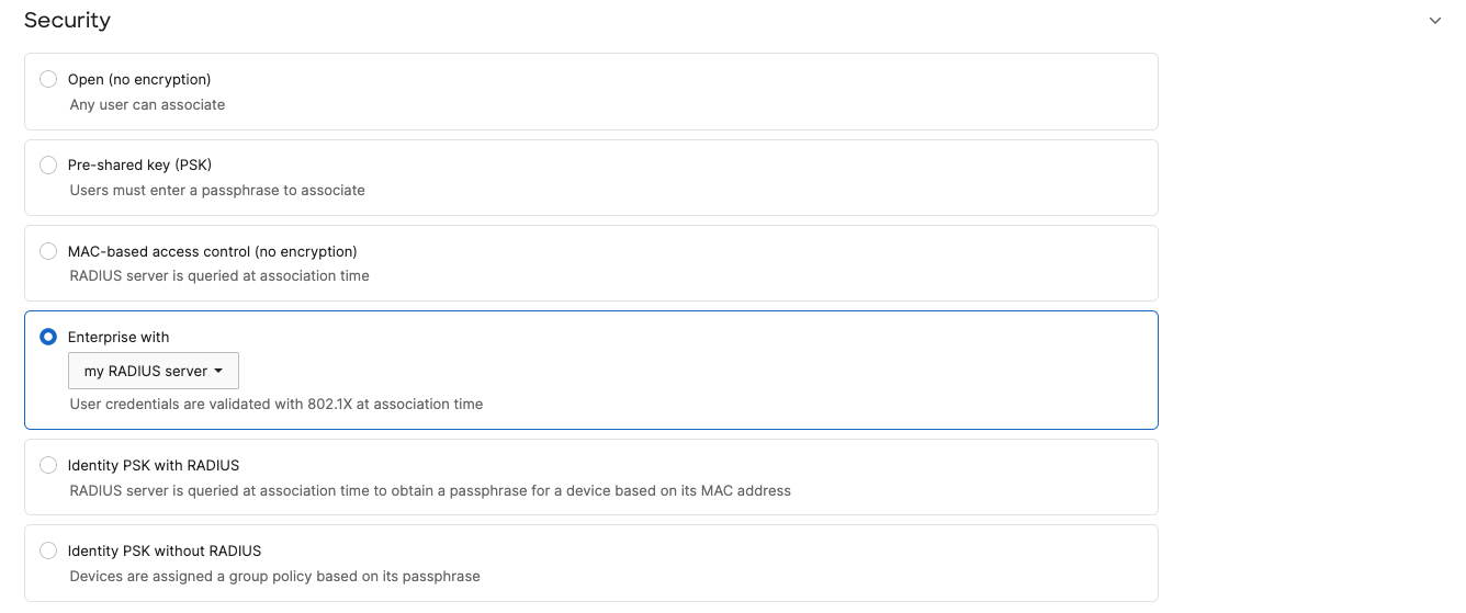
- From the Access Control Page, configure the Corporate SSID with the following settings:
- Association Requirements = Enterprise with myRadius server
- WPA Encryption mode: WPA1 and WPA2
- Splash page = None
- Add a Radius server with Host = <ISE Private IP Address in AWS> (172.31.16.31 per the topology above), Port = 1812, Secret = <ISE secret that you have created in the previous section when you added a Network Device>
- Under Client IP Assignment, choose VPN: tunnel data to a concentrator(1)
- Choose your vMX as the concentrator
- VLAN tagging = Choose the VLAN for Corporate traffic (VLAN 10 in this case per topology above)
- VPN tunnel type = Split tunnel (2)
- Add a VPN Split tunnel rule with your AWS subnet (172.31.16.0/20 in this case per topology above) and make sure to send traffic over VPN tunnel
- Click Save Changes


That concludes the steps required to configure MR with SSID tunnelling to your vMX in AWS.
Please repeat the above steps for each SSID that needs to be tunnelled to the vMX in AWS
(1) Please note that in case of using MX appliances on site, the SSID should be configured in Bridge mode with traffic tagged in the designated VLAN (All other configuration items remains the same). The above configuration reflects the design topology shown above with MR access points tunnelling directly to the vMX.
(2) Please note that for local breakout traffic, it will be NAT'd with the MR uplink IP address since the DHCP pool used for the clients on this SSID resides on the remote vMX
Adding a Secondary Concentrator to your SSID(s) - Optional
The following section explains the additional configuration needed in case of using a Secondary Concentrator in AWS.
First, you will need to designate an IP address on the concentrators to be used for tunnel checks. The designated IP address will be used by the MR access points to mark the tunnel as UP or Down. The access points sends a DHCP request for this IP address and a response from the vMX should mark the tunnel as UP.
For this, you will need the IP addresses that has already been configured under DHCP settings on both your vMXs. (Please refer to the following section)
Please note that DHCP requests sent from the access point are tagged with the configured VLAN on that SSID.
When you are configuring your SSIDs in the Access control menu, please follow these steps:
To be able to see the secondary concentrator option in dashboard, you will need to view the New version of the Access Control Page by clicking on the top right corner

The following configuration is needed on dashboard in addition to the steps mentioned in the Dashboard Configuration section above.
- Navigate to your wireless network
- From wireless menu, click on Access Control
- Click on View new version from the top right corner
- Choose the SSID from the top drop down menu
- Under Client IP and VLAN menu, Click on Tunnelled
- Choose "VPN tunnel data to concentrator"
- Concentrator = your primary vMX referenced by it's network name
- Secondary concentrator = your secondary vMX referenced by it's network name
- Tunnel Health Check IP = your fixed IP address (e.g. 10.10.10.2, 10.10.20.2, 10.10.90.2). Please note that this IP needs to be in the range of which this SSID is being terminated in on the vMX side (e.g. VLAN 10, 20 or 90). As explained above, you can use the IP address assigned to the vMX within the specified VLAN that the SSID is tagged with (For instance, VLAN 10 for Corporate SSID)
- Tunnel heartbeat interval = 10 (Frequency of sending DHCP requests)
- Tunnel idle timeout = 30 (Time to failover to secondary concentrator, by first checking it's tunnel status)
- De-associate clients on tunnel failover = Don't reassociate
- Repeat steps 4-11 for your other SSIDs that are tunnelled to a concentrator
At this stage, your MR access points will form one tunnel to each concentrator configured in dashboard.

The above configuration is shown for the Corporate SSID. Other SSIDs tunnelled to a concentrator should show the same config except for the "Tunnel Health Check IP" which needs to be within the VLAN used to tag traffic from this SSID. Remember that DHCP traffic will be tagged with the same VLAN that is used to tag the SSID traffic.
It is recommended that the Tunnel Idle Timeout is multiples of your Tunnel Heartbeat Interval (e.g. 10 and 30, 15 and 45, etc.)
It is not recommended to reduce the Tunnel Heartbeat Interval or the Tunnel Idle Timeout as this can lead to undesired behaviour.
The last step was to choose between the following two options:

Reassociate = Force clients to re-associate and trigger a new DHCP request
Don't Reassociate = Do not force clients to re-associate which can offer a more seamless failover
Please note that the client association during failover will always be dependent on the client behaviour (e.g. Other known SSIDs on the client, SSID preferences, etc.). As such, the client might need to re-associate with the SSID after failover.
Testing and Verification
Prior to testing, please ensure that the Client Certificate has been pushed to the endpoint and that it meets the EAP-TLS requirements. For more information, please refer to the following document.
Please note that it is NOT recommended to use self-signed certificates in production environments. A Certificate Authority (CA) signed certificate is more secure thus should be in production.
To test and verify your configuration, simply associate an endpoint with one of the SSIDs configured earlier. (e.g. Corporate). You will need to use one of the accounts previously created on Azure Active Directory (e.g. Corp1)
The following checks can be done to verify a successful implementation:
SSID is being broadcasted (Unless it has been hidden)

Please note that the SSID won't be broadcasting if the VPN tunnel between the MR Access Point and the vMX is not established. You can use the Test button on the Meraki dashboard to test connectivity to your vMX concentrator (Navigate to Wireless > Configure > Access control then scroll down to Addressing and traffic and next to the concentrator box there should be a "Test" button)

To verify that the tunnel from the MR access point to the vMX is established, Go to your MR Network in dashboard and navigate to Network-wide > Monitor > Event log. The connectivity status should be "true" for an established tunnel

You can also verify that the tunnel from the MR access point to the vMX is established on the vMX side, Go to your vMX Network in dashboard and navigate to Network-wide > Monitor > Event log and then filter for All Meraki VPN. The connectivity status should be "true" for an established tunnel


Client associates with the SSID (e.g. Corporate)

To verify the client association to the SSID, Go to your MR Network in dashboard and navigate to Network-wide > Monitor > Event log and then filter for Client. That will show you the association status for the client as well as the authentication status

Client is online on dashboard (Navigate to Network-wide > Monitor > Clients)

You can also ping the client from dashboard by clicking on the Client from the list above and pinging it directly from the Client Details page. (You can do that from both the MR network and the vMX network)
MR ping to Client

vMX ping to Client
Client acquires an IP Address within a range configured on the vMX

Cisco ISE logs show a successful authentication process with the correct username, protocol and Identity Store
On the Cisco ISE Web Console, navigate to main menu > Operations > Live logs and then search for the client's log and click on Details


Client has connectivity to AWS workloads (where applicable)

Please note that this requires a split tunnel rule to be configured under Access Control Page for the SSID.

Split tunnelling working as expected (Local breakout vs In-tunnel traffic).
For this we will be using a destination host that is configured to use the tunnel (e.g. 172.31.16.31 in our case per topology above) and another destination host that is configured to break out locally. We will be taking a packet capture from Meraki dashboard on the wired interface of the MR Access Point (Navigate to Network-wide > Monitor > Packet capture) to verify which traffic is dropped on the MR's uplink (local breakout) and which traffic is sent in-tunnel
Local Breakout traffic
Ping 23.212.109.49


Please note that local breakout traffic will be NAT'd with the MR's uplink IP address (192.168.1.34 in this case)

In-tunnel traffic
Ping 172.31.16.312


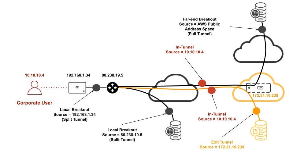
Client IP Addressing
Clients will acquire an IP Address from the DHCP pool configured on the vMX and that is configured on the MR's Access control page to concentrate traffic from this SSID. This will be the in-tunnel IP address. Once the traffic lands on the vMX it will be NAT'd with the vMX uplink IP address when it get's routed elsewhere. For local breakout, traffic will be NAT'd to the MR Uplink IP address.
Please see the below diagram to illustrate IP addressing from a client's point of view:
Failover Testing
In this section, we will test the client behaviour during a failover scenario. To simulate a failure on the primary concentrator, you can either reboot the vMX from the Meraki dashboard OR stop the instance from which the primary vMX is running from your AWS console (EC2 > Instances):


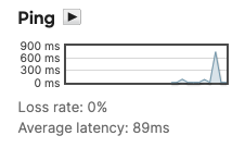
For the purpose of this CVD, we have used the second option (to Stop the AWS instance). Once that is completed, the vMX-2A appliance should show offline on the Meraki dashboard. To test in-tunnel traffic, we will ping the ISE server IP address (172.31.16.31) from the client associated with the Corporate SSID.
Steady State (i.e. Both Concentrators UP)
Meraki dashboard status
AWS instances' status
ICMP test (client -> 172.31.16.31)

ISE authentication logs

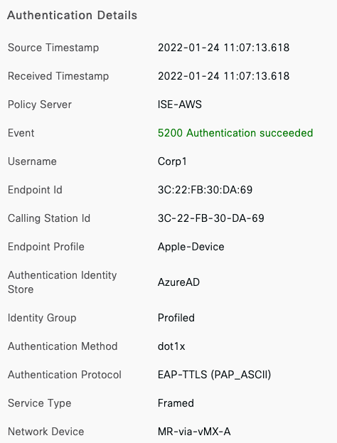
Please note that in this case ISE shows the Primary vMX (MR-via-vMX-B) as the Network Device initiating the authentication request
Failover State (i.e. Primary Concentrator DOWN)
To simulate a situation with the primary concentrator going down, we will stop the instance in the AWS console until the primary vMX goes down.
From the AWS console, navigate to EC2 then instances and select the instance where the primary vMX is deployed and from the instance state menu choose Stop instance and finally click on Stop to confirm:


After several minutes, the instance should be showing as Stopped (You might need to refresh your browser)

Meraki dashboard status
Primary vMX goes down on the Meraki Dashboard (This might take some minutes to reflect on the Meraki dashboard):

AWS instances' status
ICMP test (client -> 172.31.16.31)

The AP will mark the tunnel down after the Idle timeout interval, after which traffic will failover to the secondary concentrator.
It is recommended to configure the client with Auto-Rejoin to avoid the end user having to re-associate with the SSID
ISE authentication logs


Please note that in this case ISE shows the Secondary vMX (MR-via-vMX-B) as the Network Device initiating the authentication request
Fallback State (i.e. Primary Concentrator back UP)
To simulate a scenario where the Primary Concentrator has come back, we will start the instance in the AWS console. After a few moments, the instnace should show as Running:
Meraki dashboard status
AWS instances' status
ICMP test (client -> 172.31.16.31)

It is recommended to configure the client with Auto-Rejoin to avoid the end user having to re-associate with the SSID