
Configuring PoE on MS switches
Overview
Meraki MS switches with model numbers ending in P, LP, or FP can power devices with Power Over Ethernet (PoE). This article provides an overview of the general configuration of PoE on Meraki switches from the Meraki dashboard. Additional information about model-specific features can be found in the MS Family datasheet for reference.
Learn more with this free online training course on the Meraki Learning Hub:
Dashboard Configuration
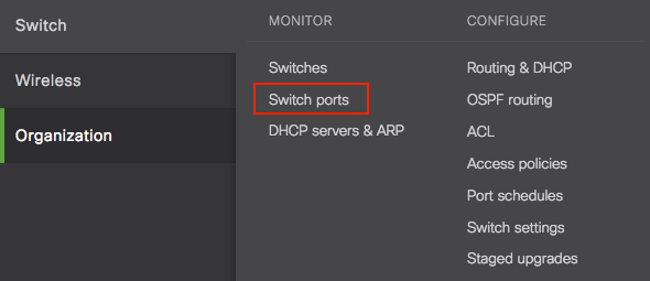
PoE settings can be configured using the dashboard on a per-port basis. This can be done by navigating to the Switch > Monitor > Switch ports page on the dashboard like the example below:
- Navigate to Switch > Monitor > Switch ports
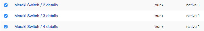
- Select the switchports that you wish to configure by selecting the checkbox to the left of the port description.
- At the top left of the table select Edit, which will bring up a new dialog box where port-specific settings can be configured.
- Here PoE can be Enabled or Disabled for the selected ports from Step 2.
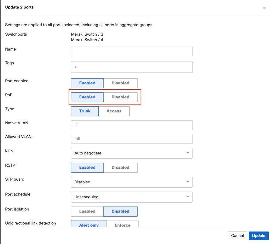
- Once the setting has been configured click Update to save the port settings.
Monitoring PoE on Dashboard
When PoE devices are connected to PoE enabled ports of MS switches, the ports on the Switch Details page for the switch are shown with a lightning bolt, as seen below. This symbol indicates that power from these interfaces is being supplied from the switch (PSE) to the powered device(s) (PD).

PoE consumption on the switch can be monitored live, including both the overall Consumption and Budgeted values as well as port-specific information. This can be seen by navigating to the Switch > Monitor > Switches > Switch Details page for a specific switch, then selecting the Power tab. To view port-specific information, select the Ports tab or an individual switchport from the Switch Details page instead.
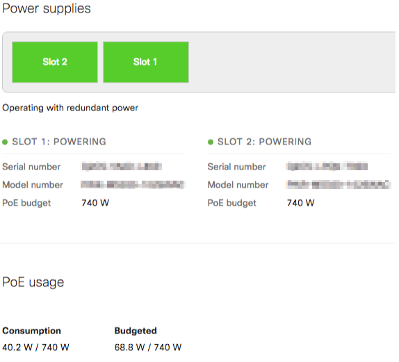
The Consumption value shows overall real-time consumption across the switch, while the Budgeted value indicates how much power is potentially available for provisioning additional PoE devices. Depending on the switch model, available power supplies, and which PoE mode the switch is configured for (Redundant Power or Combined Power), the total available PoE budget will vary.
For more information on Combined Power please refer to our article on Combined Power on MS Devices. For more information about the available PoE budget of each MS hardware model, please see the MS Family Datasheet.
Note: The switches will budget based on the device PoE classification. The PoE budget value is allowed to exceed the maximum available power as it is used only to gauge potential overall power that might be consumed on the switch. Devices will continue to be powered until the actual Consumption goes over the maximum available amount of power the switch can provide. In this case, the lowest port numbers take precedence and power will be pulled from the highest ports, thus denying them power.