
MT Troubleshooting Guide
Overview
This article is intended to guide you through troubleshooting some common scenarios that may occur during normal operation. This article is divided into troubleshooting steps that pertain to all models along with model specific troubleshooting steps.
If your issue isn’t included in this document or the steps listed do not resolve your issue, please contact Cisco Meraki Support for further assistance.
All MT Models
Device Fails to Power on
All models of MT sensors feature a multi-color LED on their ‘Front’ or ‘Top’ surface, which is illuminated briefly on power-on or if the 'General Purpose' button is pressed.
If this light does not illuminate even after the 'General Purpose' button is pressed:
- Ensure that the sensor’s battery is inserted in the correct direction as indicated on the device in the battery recess
- Try a new battery or provide the MT power via a USB-C power source, if applicable.
Device Fails to Connect to Dashboard
MT sensors require an MR Access Point or MV Security Camera to act as a network gateway and will check in to dashboard every 20 minutes. A sensor will be marked as offline after it misses three consecutive check-ins (3 x 20-minute check-in periods.)
The MT40 differs from this and sends advertisements every 30 seconds to dashboard. If the MT40 does not check for a period greater than 5 minutes it will be marked as offline.
- MR gateway devices must be Wi-Fi 6-capable or later generation models running MR 27.6+ firmware or Wi-Fi 5-capable (802.11ac Wave 2) models running MR28.6+ firmware
- MV gateway devices must be 2nd generation or later models and must be running MV 4.8+ firmware
IoT Radio(formerly known as BLE) is only enabled on MR APs running with full power mode (PoE 802.3at unless otherwise stated in MR AP datasheet). If an AP is running with low power mode, MT sensors will NOT connect.
If the MT sensor is failing to connect to Dashboard:
- Ensure the MT sensor is added to the same network as the MV/MR gateway
- Trigger an event for the MT sensor
- MT10/12/20 - Press the 'General Purpose' button on top of the device
- MT20 - Bring the sensor bar within 0.1 - 2.0 centimeters of magnet symbol
- Increase the MT sensor proximity to a known-working MR or MV gateway
MT sensors contact Dashboard via Bluetooth Low-Energy®. As such their range can be affected by the local 2.4 Ghz wireless environment.
LED Indicator Reference
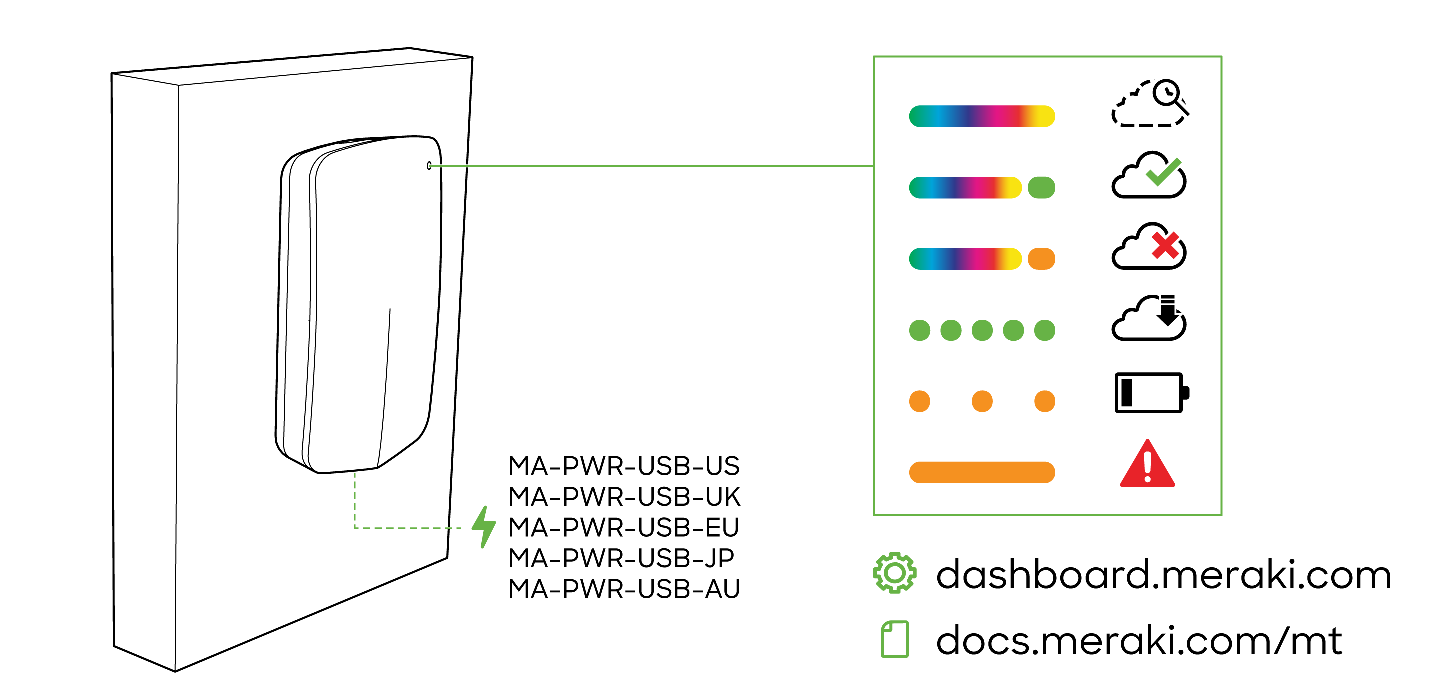
- Rainbow = MT is initializing or looking for a gateway.
- Solid green (for three seconds) = connected to a gateway.
- Solid amber (for three seconds) = MT could not find a gateway to connect.
- Flashing green = MT is upgrading its firmware.
- Flashing amber = MT is running on a low battery.
Note: To conserve battery life, the LEDs don't always remain on.
The exact position of the LED indicator may vary from the image displayed above.
MT10 - Temperature/Humidity Sensor
Temperature/Humidity not Accurate
The MT10 temperature and Humidity sensors are internal. If the MT10 is mounted in a location with limited airflow it may take an extended period of time for the sensor to register a large temperature/humidity swing.
This time may be improved by increasing/allowing airflow to the opening in the housing located adjacent to the USB-C port on the ‘bottom’ of the device.
For more information about the charts, please refer to our MT Psychrometric Chart document.
MT12 - Water Leak Sensor
Cable Disconnected
Ensure that the cable is fully seated in the cable port, as shown below.
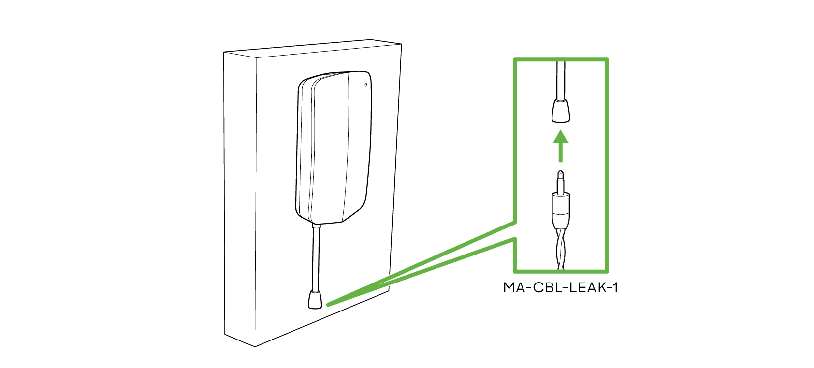
There should be a ‘click’ when the cable fully seats, with nearly no space between the ground sheaths of the male and female ends of the connectors
Cable Detected as Wet
Ensure that the cable is undamaged, and has had sufficient time to dry out from the last wet event.
The cable will be detected as wet with as little as 3 ml of normal water. This means that if the cable becomes fully submerged, it could take a considerable amount of time to dry out fully. This is especially true if any water finds its way into the female end of the water detection cable.
MT20 - Open/Close Sensor
Device Tampering
The MT20 uses a Hall Effect sensor to detect magnetic field strength. When the sensor detects a higher than expected magnetic flux, the MT20 will report a device tampered state.
If your sensor is alerting for Device Tampering, ensure that:
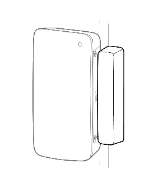
- You are using the included magnet bar
- The gap between the MT20 and the magnet bar does not fall below 5 millimeters (0.5 cm)
Device Always Reporting as ‘Open’
The MT20 is calibrated to show as 'Closed' when the included magnet bar is between 5 - 20 millimeters (0.5 - 2 cm) away from the MT20 magnet symbol.
If your sensor is always showing as open, ensure that the following is true when the door is physically closed:
- The magnet bar is within 5 - 20 millimeters (0.5 - 2 cm) of the MT20 magnet symbol
- The magnet bar is parallel to the MT20
- The magnet symbols on the MT20 and magnet bar are facing each other
Instructions on how to properly mount the MT20 and magnet bar can be found in the MT20 Installation Guide