
Datacenter Redundancy (DC-DC Failover) Deployment Guide
Overview
Cisco Meraki's Datacenter Redundancy (DC-DC Failover) feature allows for network traffic sent across AutoVPN to failover between multiple geographically distributed datacenters. This guide introduces the various components of DC-DC failover and the possible ways in which to deploy a DC-DC failover architecture.
Key Concepts
Before deploying DC-DC Failover, it is important to understand several key concepts.
Concentrator Mode
All MXs can be configured in either NAT or VPN concentrator mode. There are important considerations for both modes. For more detailed information on concentrator modes, click here.
One-Armed Concentrator
In this mode the MX is configured with a single Ethernet connection to the upstream network. All traffic will be sent and received on this interface. This is the recommended configuration for MX appliances serving as VPN termination points into the datacenter.
NAT Mode Concentrator
In this mode the MX is configured with a single Ethernet connection to the upstream network and one Ethernet connection to the downstream network. VPN traffic is received and sent on the WAN interfaces connecting the MX to the upstream network and the decrypted, unencapsulated traffic is sent and received on the LAN interface that connects the MX to the downstream network.
VPN Topology
There are several options available for the structure of the VPN deployment.
Split Tunnel
In this configuration, branches will only send traffic across the VPN if it is destined for a specific subnet that is being advertised into the AutoVPN topology by another MX in the same Dashboard organization. The remaining traffic will be checked against other available routes, such as static LAN routes and third-party VPN routes, and if not matched will be NATed and sent out the branch MX unencrypted.
Full Tunnel
In full tunnel mode all traffic that the branch or remote office does not have another available route to is sent to a VPN hub.
Hub and Spoke
In a hub and spoke configuration, the MX security appliances at the branches and remote offices connect directly to specific MX appliances and will not form tunnels to other MX or Z1 devices in the organization. Communication between branch sites or remote offices is available through the configured VPN hubs.
VPN Mesh
In a mesh configuration, an MX appliance at the branch or remote office is configured to connect directly to any other MXs in the organization that are also in mesh mode, as well as any spoke MXs that are configured to use it as a hub.
Architecture
A DC-DC failover architecture is as follows:
- One-armed VPN concentrators or NAT mode concentrators in each DC
- A subnet(s) or static route(s) advertised by two or more concentrators
- Hub & Spoke or VPN Mesh topology
- Split or full tunnel configuration
Note: All WAN appliances participating in a DC-DC failover and advertising identical routes must be configured in the same deployment mode. It is not supported to have a WAN appliance at one DC location in NAT/Routed mode while the other DC is in Passthrough/VPN Concentrator mode, as route failover will not occur.
| DC-DC Failover Supported Architectures |
Split Tunnel |
Full Tunnel |
||
| NAT Mode Concentrator | One-Armed Concentrator | NAT Mode Concentrator | One-Armed Concentrator | |
| Hub & Spoke | ✔ | ✔ | ✔ | ✔ |
| VPN Mesh | ✔ | ✔ | ✔ | ✔ |
Operation and Failover
Deploying one or more MXs to act as VPN concentrators in additional datacenters provides greater redundancy for critical network services. In a dual- or multi-datacenter configuration, identical subnets are advertised from each datacenter with a VPN concentrator mode MX.
In a DC-DC failover design, a remote site will form VPN tunnels to all configured VPN hubs for the network. For subnets that are unique to a particular hub, traffic will be routed directly to that hub. For subnets that are advertised from multiple hubs, spokes sites will send traffic to the highest priority hub that is reachable.
When an MX Security Appliance is configured to connect to multiple VPN concentrators advertising the same subnets, the routes to those subnets become tracked. Hello messages are periodically sent across the tunnels from the remote site to the VPN hubs to monitor connectivity. If the tunnel to the highest priority hub goes down, the route is removed from the route table and traffic is routed to the next highest priority hub that is reachable.
This route failover operation only applies when identical routes are advertised from multiple AutoVPN hubs.
Warning: Failover between datacenters typically occurs in 20 to 30 seconds after connectivity between the remote site and the datacenter is lost. The failover time will vary if utilizing BGP, due to the iBGP hold-timer.
Datacenter Deployment
DC-DC failover can be configured with either a one-armed VPN concentrator or a NAT mode concentrator at each datacenter location.
Configuring a One-Armed Concentrator
A Cisco Meraki MX can be provisioned as a VPN concentrator at each datacenter remote sites will need to connect to. This section will provide a brief overview of configuring a one-armed concentrators and discuss special configuration considerations. For more detailed steps on configuring a one-armed concentrator, please refer to this article.
Example Topology
The following diagram shows an example topology using a hub & spoke configuration with a one-armed VPN concentrator.

IP Assignment
In the datacenter, an MX Security Appliance can operate using a static IP address or an address from DHCP. MX appliances will attempt to pull DHCP addresses by default. It is highly recommended to assign static IP addresses to VPN concentrators.
Static IP assignment can be configured via the device local status page.
Operating Mode Configuration
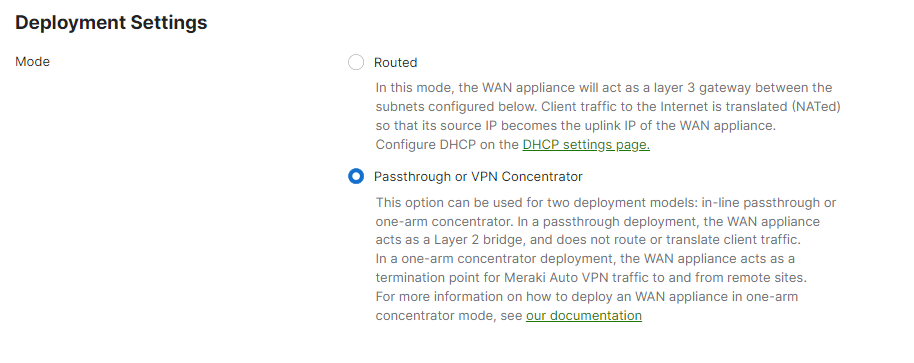
Begin by configuring the MX to operate in VPN Concentrator mode. This setting is found on the Security & SD-WAN > Configure > Addressing & VLANs page. The MX will be set to operate in NAT mode by default.
Site-to-site VPN Configuration
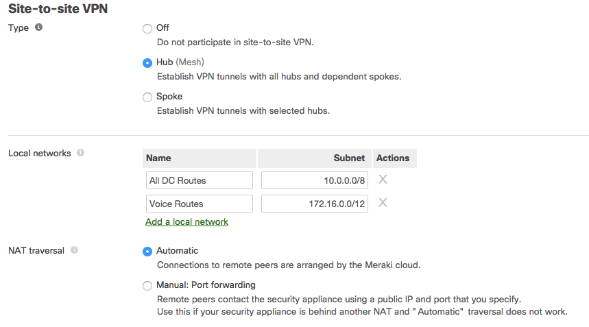
Next, configure the local networks that are accessible upstream of this VPN concentrator.
First, set the type to Hub (Mesh). Then for the local networks configuration name, specify a descriptive title for the subnet. For the subnet, specify the subnet to be advertised to other AutoVPN peers using CIDR notation. NAT traversal can be set to either automatic or manual. An example screenshot is included below:
Configure a NAT-Mode Concentrator
A Cisco Meraki MX can be provisioned as a VPN concentrator at each datacenter remote sites will need to connect to. This section will provide a brief overview of configuring a NAT mode concentrator and discuss special configuration considerations. For more detailed steps on configuring a NAT mode concentrator, please refer to this article.
Example Topology
The following diagram shows an example topology using a hub & spoke configuration with a NAT mode VPN concentrator.

IP Assignment
In the datacenter, an MX Security Appliance can operate using a static IP address or an address from DHCP. MX appliances will attempt to pull DHCP addresses by default. It is highly recommended to assign static IP addresses to VPN concentrators.
Static IP assignment can be configured via the device local status page.
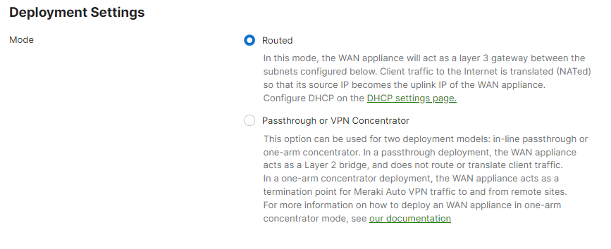
Operating Mode Configuration
Begin by configuring the MX to operate in Routed mode. This setting is found on the Security & SD-WAN > Configure > Addressing & VLANs page.
Static Route Configuration
DC-DC failover for NAT mode MXs requires redundant static routes be advertised into the AutoVPN topology from two or more NAT mode concentrators. Any local VLAN configured to be advertised into the AutoVPN topology on a NAT mode MX must be unique.
To define a static route, begin by navigating to the Security & SD-WAN > Configure > Addressing & VLANs page.
Click on the Add static route to open the Static Route configuration menu.
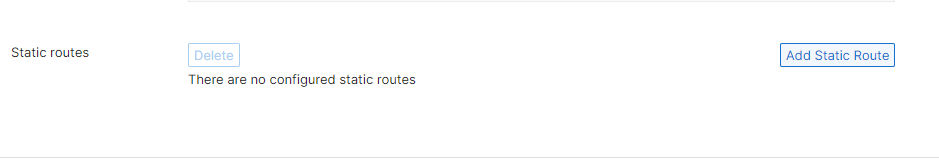
In the Static Route configuration menu, define the Name, Subnet, Next hop IP, Active state, and the VPN Mode status.
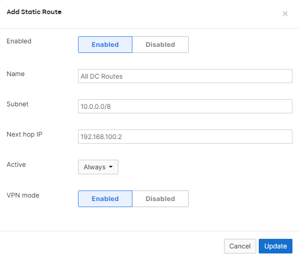
The in VPN configuration option on the static route configuration menu will only appear if VPN has already been enabled on the Security & SD-WAN > Configure > Site-to-site VPN page.
Static routes can also be configured to be advertised into the AutoVPN topology from the Site-to-site VPN page.
Please see here for more information on configuring static routes on NAT mode MXs.
Site-to-site VPN Configuration
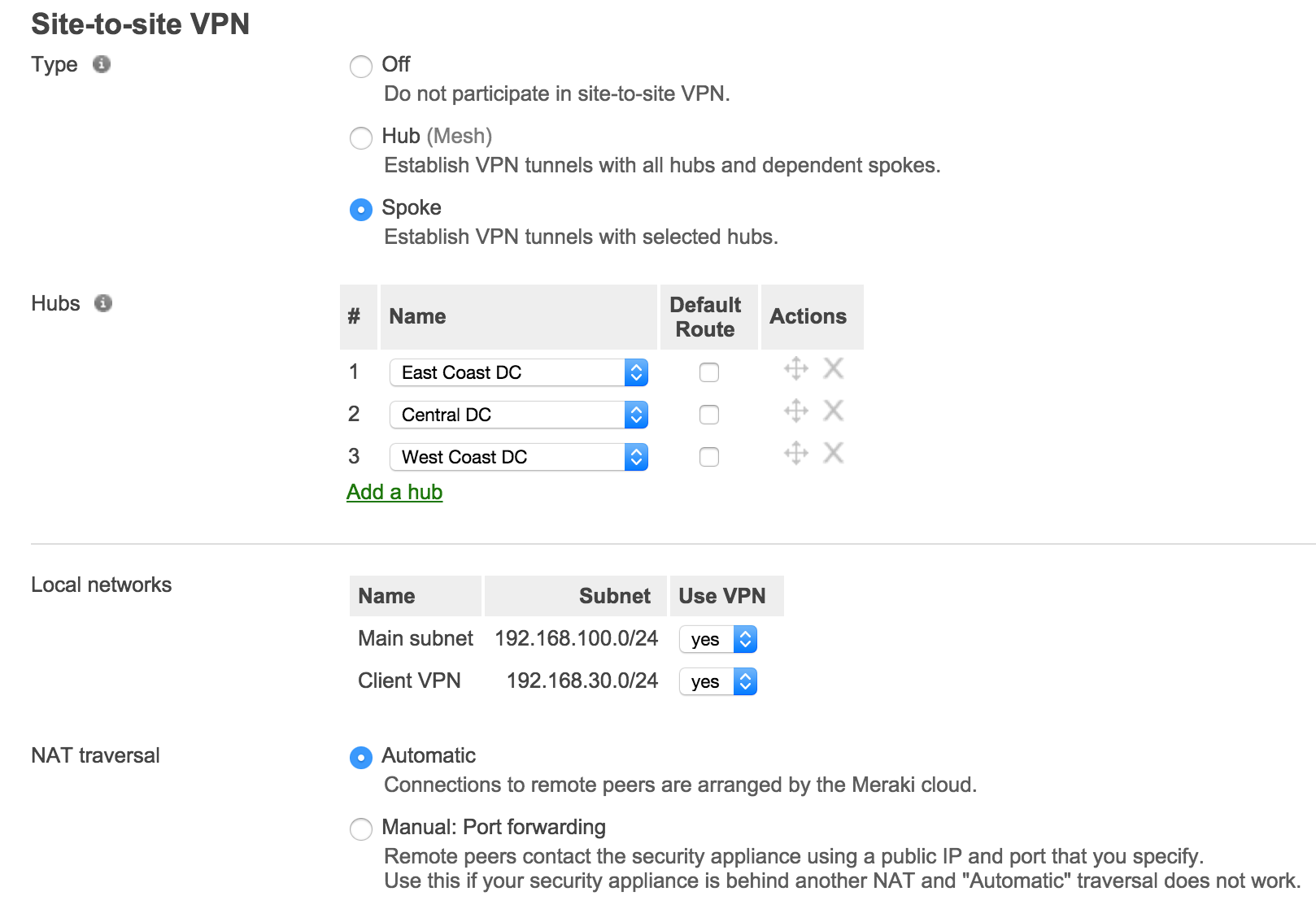
Next, enable site-to-site VPN and configure the static routes that are allowed in the VPN.
First, set the type to Hub (Mesh). Then for the local networks configuration, set use VPN to yes for subnets that should be advertised to AutoVPN peers. NAT traversal can be set to either automatic or manual. An example screenshot is included below:

Configuring Additional Datacenters
The same steps used above can also be used to deploy additional one-armed or NAT mode concentrators at one or more additional datacenters.
To provide redundant access to a specific set of datacenter resources, the subnet must be defined in the local networks for each additional datacenter and allowed to use VPN for each concentrator that can provide access to the subnet.
Concentrator Priority
When multiple VPN hubs are configured for an organization, the concentrator priority can be configured for the organization. This setting determines the order in which VPN mesh peers will prefer to connect to subnets advertised by multiple VPN concentrators.
Note: This setting does not apply to remote sites configured as VPN spokes.
Additional Datacenter Considerations
In addition to the deployment steps above, a warm spare concentrator configuration and OSPF route advertisement should be taken into consideration for MXs acting as VPN concentrators in a datacenter.
Warm Spare
A warm spare configuration uses two MX VPN concentrators in a single datacenter, with one MX serving as a stand-by warm spare to ensure high availably. More information about MX warm spare configuration can be found here.
Branch Deployment
This section will outline the configuration and implementation of the DC-DC failover architecture in the branch.
Prerequisites
Before configuring and building AutoVPN tunnels, there are several configuration steps that should be reviewed.
WAN Interface Configuration
While automatic uplink configuration via DHCP is sufficient in many cases, some deployments may require manual uplink configuration of the MX security appliance at the branch. The procedure for assigning static IP addresses to WAN interfaces can be found here.
Some MX models have only one dedicated Internet port and require a LAN port be configured to act as a secondary Internet port via the device local status page if two uplink connections are required. This currently includes all MX models other than the MX65, MX65W, MX84, MX400, and MX600. This configuration change can be performed on the device local status page on the Configure tab.
Subnet Configuration
AutoVPN allows for the addition and removal of subnets from the AutoVPN topology with a few clicks. The appropriate subnets should be configured before proceeding with the site-to-site VPN configuration.
Begin by configuring the subnets to be used at the branch from the Security & SD-WAN > Configure > Addressing & VLANs page. The branch MX can be configured to only use a Single LAN, or can be configured with multiple VLANs. Each VLAN can individually be configured to be allowed in the VPN or not.
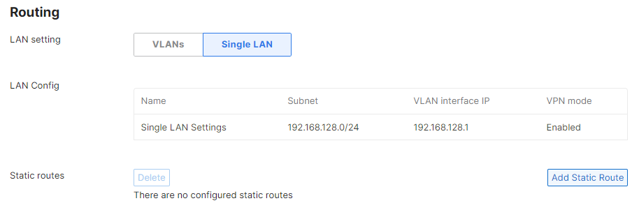
To configure the local subnet when VLANs are disabled, click on the default subnet in the LAN Config section and adjust the subnet and VLAN Interface IP.
To configure VLANs, set the LAN Setting to VLANs. To modify the default VLAN, click on its entry in the LAN Config section. To add additional VLANs, click the Add VLAN link besides the Subnets section and define the Name, Subnet, VLAN Interface IP, and VLAN ID.
For more information on configuring subnets, VLANs, and static routes on an MX appliance please see this article.
Configuring AutoVPN
Once the subnets have been configured, Cisco Meraki's AutoVPN can be configured via the Security & SD-WAN > Configure > Site-to-site VPN page in Dashboard.
Configuring Hub and Spoke VPN
From the Security & SD-WAN > Configure > Site-to-Site VPN page:
- Select spoke for the type
- Under Hubs, select Add a hub
- To connect to additional hubs, select Add a hub and select the VPN concentrator configured in the datacenter deployment steps
- Additional hubs can be added by repeating steps 2 and 3
Hub priorities
Hub priority is based on the position of individual hubs in the hubs list from top to bottom. The first hub has the highest priority, the second hub the second highest priority, and so on. Traffic destined for subnets advertised from multiple hubs will be sent to the highest priority hub that has an established VPN connection with the spoke. Traffic to subnets advertised by only one hub is sent directly to that hub.
To leverage DC-DC failover, the branch site must have at least two hubs defined in the site-to-site VPN page that advertise the same subnet into the AutoVPN topology (split tunnel) or that the default route checkbox is selected for (full tunnel).
Configuring split and full-tunnel VPN connections
To configure full tunnel VPN to a particular hub, check the default route box.
To configure split tunnel VPN to a particular hub, do not select the default route for the VPN hub.
DC-DC failover can be leveraged in split tunnel configurations, full tunnel configurations, as well as in mixed configurations. In a mixed configuration where the branch connects to some VPN hubs with a full tunnel connection and some as split tunnel connection, it is important to remember that redundancy is only provided for subnets that are advertised as two or more hub's local networks.
Configuring Allowed Networks
To allow a particular subnet to communicate across the VPN, locate the local networks section in the Security & SD-WAN > Configure > Site-to-site VPN page. The list of subnets is populated from the configured local subnets and static routes in the Security & SD-WAN > Configure > Addressing & VLANs page, as well as the Client VPN subnet if one is configured.
To allow a subnet to use the VPN, set the use VPN drop-down to yes for that subnet.
NAT Traversal
Please refer to the datacenter deployment steps here for more information on NAT Traversal options.
VPN Mesh Configuration
From the Security & SD-WAN > Configure > Site-to-Site VPN page:
- Select Hub for the type

A VPN hub will form AutoVPN tunnels to all other configured VPN hubs in the organization and all of it's configured VPN spoke sites.
Configuring split and full-tunnel VPN connections
To configure full tunnel VPN to a particular hub, an exit hub will need to be defined. Click add a hub and select the desired exit hub. Multiple exit hubs can be defined.
Split tunnel connections are made from the branch location to all other VPN hubs that are not designated in the list of exit hubs.
Configuring Allowed Networks
To allow a particular subnet to communicate across the VPN, locate the local networks section in the Site-to-site VPN page. The list of subnets is populated from the configured local subnets and static routes in the Addressing & VLANs page, as well as the Client VPN subnet if one is configured.
To allow a subnet to use the VPN, set the use VPN drop-down to yes for that subnet.
Hub priorities
Hub priority in a VPN mesh configuration is based on the position of individual hubs in the concentrator priority list and the list of exit hubs, from top to bottom.
Concentrator priority is an organization-wide setting that affects the priority for split tunnel connections between hubs.

Exit hub configurations are specific to an individual MX network and affect full tunnel connections between hubs. When exit hubs are defined, traffic that the branch does not have another available route to is sent to the configured exit hubs.

In both cases, the first hub has the highest priority, the second hub the second highest priority, and so on. Traffic destined for subnets advertised from multiple hubs will be sent to the highest priority hub that currently has an established VPN connection with the site. Traffic to subnets advertised by only one hub will be sent directly to that hub.
To leverage DC-DC failover, the branch site must have at least two hubs defined in the site-to-site VPN page that advertise the same subnet into the AutoVPN topology (split tunnel) or that have been designated as exit hubs (full tunnel).
NAT Traversal
Please refer to the datacenter deployment steps here for more information on NAT Traversal options.
Routing Considerations
MX security appliances perform decisions on how to forward traffic based on a routing table built from the network's configuration in the Meraki Dashboard. In determining the appropriate destination to forward traffic, the MX will prefer the most specific route to the destination IP address.
For more detailed information on MX routing behavior, please see this article.