
Meraki Auto VPN General Best Practices
Click 日本語 for Japanese
Auto VPN Best Practices
The best practices listed here focus on the most common deployment scenario, but is not intended to preclude the use of alternative topologies. The recommended SD-WAN architecture for most deployments is as follows:
-
WAN Appliance at the datacenter deployed as a one-armed concentrator
-
Warm spare/High Availability at the datacenter
-
OSPF route advertisement for scalable upstream connectivity to connected VPN subnets
-
Datacenter redundancy
-
Split tunnel VPN from the branches and remote offices
-
Dual WAN uplinks at all branches and remote offices
Auto VPN at the Branch
Before configuring and building Auto VPN tunnels, there are several configuration steps that should be reviewed.
WAN Interface Configuration
While automatic uplink configuration via DHCP is sufficient in many cases, some deployments may require manual uplink configuration of the WAN appliance at the branch. The procedure for assigning static IP addresses to WAN interfaces can be found in our MX IP assignment documentation.
Some WAN Appliance models have only one dedicated Internet port and require a LAN port be configured to act as a secondary Internet port via the device local status page if two uplink connections are required. WAN Appliance models that require reconfiguring a LAN port as a secondary Internet port currently include the MX64 line, MX67 line, and MX100 devices. This can also be verified per-model in our installation guides online. This configuration change can be performed on the device local status page on the Configure tab.
Subnet Configuration
Auto VPN allows for the addition and removal of subnets from the Auto VPN topology with a few clicks. The appropriate subnets should be configured before proceeding with the site-to-site VPN configuration.
Hub Priorities
Hub priority is based on the position of individual hubs in the list from top to bottom. The first hub has the highest priority, the second hub the second highest priority, and so on. Traffic destined for subnets advertised from multiple hubs will be sent to the highest priority hub that a) is advertising the subnet and b) currently has a working VPN connection with the spoke. Traffic to subnets advertised by only one hub is sent directly to that hub.
Configuring Allowed Networks
To allow a particular subnet to communicate across the VPN, locate the local networks section in the Site-to-site VPN page. The list of subnets is populated from the configured local subnets and static routes in the Addressing & VLANs page, as well as the Client VPN subnet if one is configured.
To allow a subnet to use the VPN, set the Use VPN drop-down to yes for that subnet.
Auto VPN at the Data Center
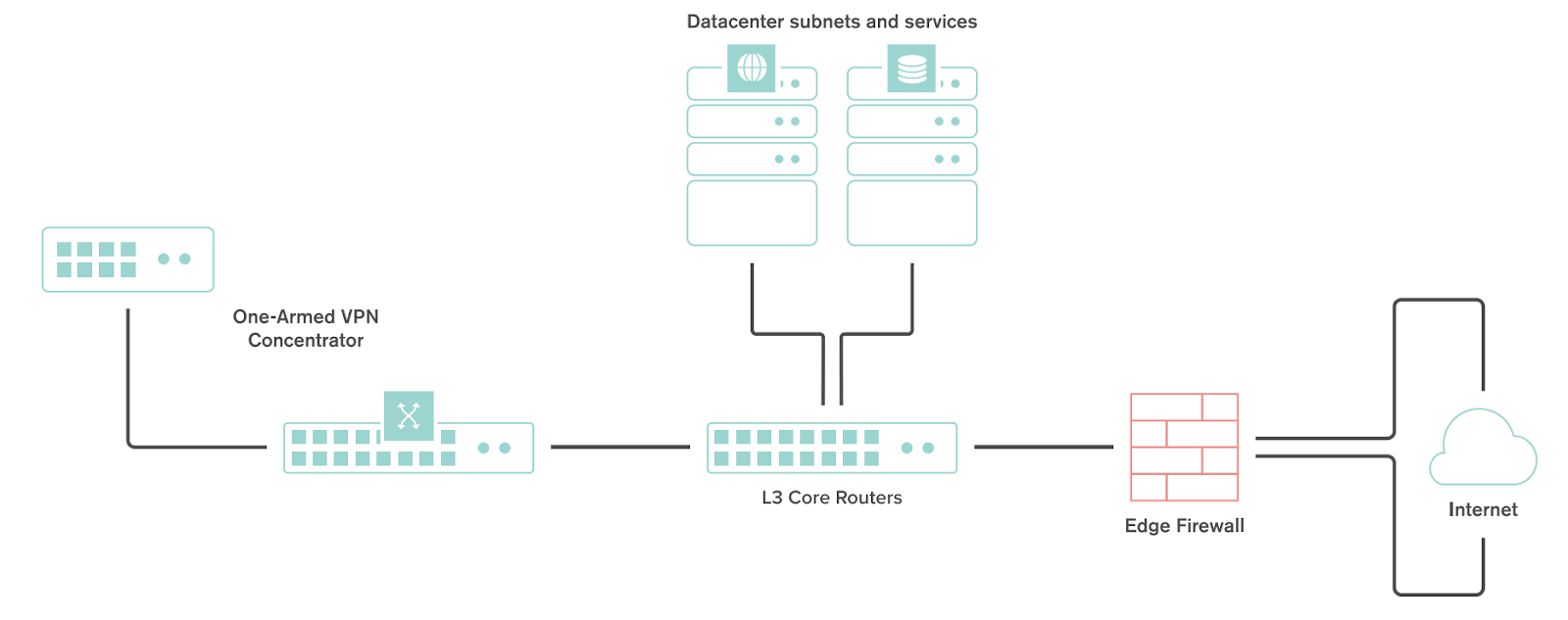
Deploying a One-Armed Concentrator
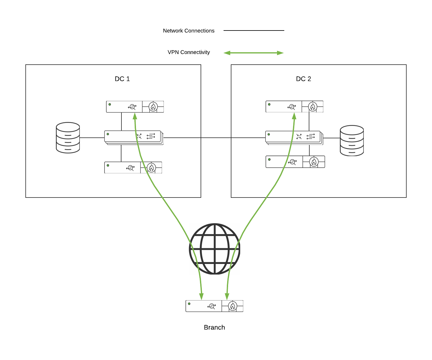
A one-armed concentrator is the recommended datacenter design choice for an SD-WAN deployment. The following diagram shows an example of a datacenter topology with a one-armed concentrator:
NAT Traversal
Whether to use Manual or Automatic NAT traversal is an important consideration for the VPN concentrator.
Use manual NAT traversal when:
-
There is an unfriendly NAT upstream.
-
Stringent firewall rules are in place to control what traffic is allowed to ingress or egress the datacenter.
-
It is important to know which port remote sites will use to communicate with the VPN concentrator.
If manual NAT traversal is selected, it is highly recommended that the VPN concentrator be assigned a static IP address. Manual NAT traversal is intended for configurations when all traffic for a specified port can be forward to the VPN concentrator.
Use automatic NAT traversal when:
-
None of the conditions listed above that would require manual NAT traversal exist.
If automatic NAT traversal is selected, the WAN Appliance will automatically select a high numbered UDP port to source Auto VPN traffic from. The VPN concentrator will reach out to the remote sites using this port, creating a stateful flow mapping in the upstream firewall that will also allow traffic initiated from the remote side through to the VPN concentrator without the need for a separate inbound firewall rule.
Datacenter Redundancy (DC-DC Failover)
Meraki WAN Appliances support datacenter to datacenter redundancy via our DC-DC failover implementation. The same steps used above can also be used to deploy one-armed concentrators at one or more additional data centers. For further information about VPN failover behavior and route prioritization, refer to our DC-DC Failover documentation.
This section outlines the steps required to configure and implement warm spare high availability (HA) for a WAN Appliance operating in VPN concentrator mode.
Topology
The following is an example of a topology that leverages an HA configuration for VPN concentrators:
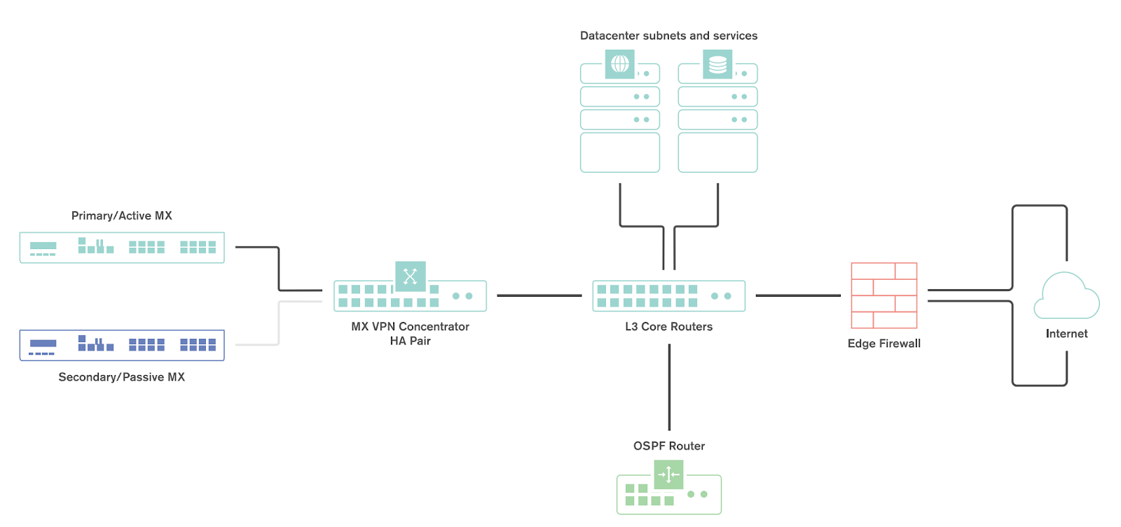
Behavior
When configured for high availability (HA), one WAN Appliance is active, serving as the primary, and the other WAN Appliance operates in a passive, standby capacity. The VRRP protocol is leveraged to achieve failover. Check out our MX Warm Spare documentation for more information.
WAN Appliance IP Assignment
In the datacenter, a WAN Appliance can operate using a static IP address or an address from DHCP. WAN appliances will attempt to pull DHCP addresses by default. It is highly recommended to assign static IP addresses to VPN concentrators.
Uplink IPs
Use Uplink IPs is selected by default for new network setups. In order to properly communicate in HA, VPN concentrator WAN Appliances must be set to use the virtual IP (VIP).
Virtual IP (VIP)
Virtual IP is an addressing option that uses an additional (third) IP address that is shared by the HA WAN Appliances. In this configuration, the WAN Appliances will send their cloud controller communications via their uplink IPs, but other traffic will be sent and received by the shared virtual IP address.
WAN Appliance Data Center Routing
The WAN Appliance acting as a VPN concentrator in the datacenter will be terminating remote subnets into the datacenter. In order for bi-directional communication to take place, the upstream network must have routes for the remote subnets that point back to the WAN Appliance acting as the VPN concentrator.
If OSPF route advertisement is not being used, static routes directing traffic destined for remote VPN subnets to the WAN Appliance VPN concentrator must be configured in the upstream routing infrastructure.
If OSPF route advertisement is enabled, upstream routers will learn routes to connected VPN subnets dynamically.
Failover Times
There are several important failover timeframes to be aware of:
|
Service |
Failover Time |
Failback Time |
|
Auto VPN Tunnels |
30-40 seconds |
30-40 seconds |
|
DC-DC Failover |
20-30 seconds |
20-30 seconds |
|
Dynamic Path Selection |
Up to 30 seconds |
Up to 30 seconds |
|
Warm Spare |
30 seconds or less |
30 seconds or less |
|
WAN connectivity |
300 seconds or less |
15-30 seconds |
Configuring OSPF Route Advertisement
Meraki WAN Appliances support advertising routes to connected VPN subnets via OSPF.
A WAN Appliance with OSPF route advertisement enabled will only advertise routes via OSPF; it will not learn OSPF routes.
Note: WAN Appliances in Routed mode only support OSPF on firmware versions 13.4+, when using the "Single LAN" LAN setting. OSPF is otherwise supported when the WAN Appliance is in passthrough mode on any available firmware version. This can be set under Security & SD-WAN > Configure > Addressing & VLANs.
When spoke sites are connected to a hub WAN Appliance, the routes to spoke sites are advertised using an LS Update message. These routes are advertised as type 2 external routes.
BGP and Auto VPN
BGP VPNs are utilized for Data Center Failover and load sharing. This is accomplished by placing VPN Concentrators at each Data Center. Each VPN Concentrator will utilize BGP with DC edge devices. BGP is utilized for its scalability and tuning capabilities.
More information about implementing BGP and its use cases can be found in our BGP documentation.
Auto VPN Technology Deep Dive
The Meraki WANAppliance makes use of several types of outbound communication. Configuration of the upstream firewall may be required to allow this communication.
Dashboard & Cloud
The Meraki WAN Appliance is a cloud managed networking device. As such, it is important to ensure that the necessary firewall policies are in place to allow for monitoring and configuration via the Meraki dashboard. The relevant destination ports and IP addresses can be found under the Help > Firewall Info page in the dashboard.
VPN Registry
Meraki's Auto VPN technology leverages a cloud-based registry service to orchestrate VPN connectivity. In order for successful Auto VPN connections to establish, the upstream firewall must allow the VPN concentrator to communicate with the VPN registry service. The relevant destination ports and IP addresses may vary by region, and can be found under the Help > Firewall Info page in the dashboard.
Uplink Health Monitoring
The WAN Appliance also performs periodic uplink health checks by reaching out to well-known Internet destinations using common protocols. The full behavior is outlined here. In order to allow for proper uplink monitoring, the following communications must also be allowed:
-
DNS test to canireachthe.net
-
Internet test to icmp.canireachthe.net
VPN Registry
In order to participate in Auto VPN a WAN Appliance must register with the Meraki VPN registry. The VPN registry is a cloud-based system that stores data needed to connect all WAN Appliances into an orchestrated VPN system. The VPN registry is always on and always updating in the case of a connection failure. This means no manual intervention is needed in the case of reboots, new public IP addresses hardware failovers etc. The VPN registry stores the following information for each WAN Appliance:
-
Subnets (for creating the VPN route table)
-
Uplink IP (public or private)
-
Public IP
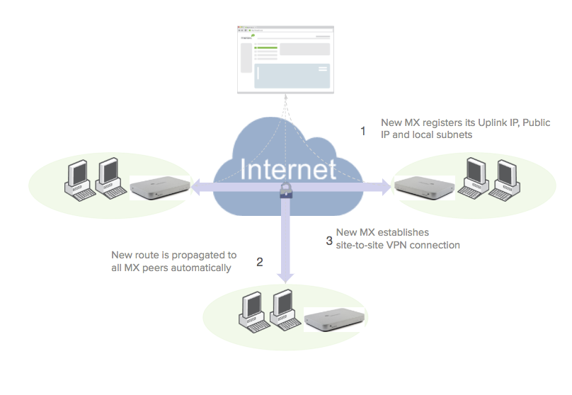
The process for adding a new WAN Appliance into an infrastructure is as follows:
-
A new WAN Appliance reports its uplink IP address(es) and shared subnets to the registry
-
The information is propagated to the other WAN Appliances in the infrastructure
-
The WAN Appliance establishes the proper VPN tunnels
-
The WAN Appliance will try the registry-reported private uplink IP of the peer first
-
If a connection to the private uplink IP of the peer fails, the WAN Appliance will try the public uplink IP of its peer
-
Auto VPN Routing
The VPN Registry stores the relevant information including, local routes participating in VPN for a particular Meraki Auto VPN infrastructure. In the case of a failure, additional VPN device, or hub change the system automatically reconverges without any end user interaction. By updating all VPN routes to all devices in the system Auto VPN acts like a routing protocol and converges the system to maintain stability.
High Availability
|
Key use case |
Cost consideration |
Failover time |
|
|
HW Redundancy |
Mitigate a WAN Appliance HW failure using 2 devices on the same broadcast domain |
Two devices are required but only a single license |
Less than 30 seconds (for hardware failover, not necessarily VPN failover) |
|
DC DC Failover |
Mitigate any problem that could prevent a spoke from reaching its primary hub |
Two devices and two licenses are required |
Between 30 seconds and 5 minutes (SD-WAN allows for faster failover) |
Hardware Redundancy in VPN Concentrator Mode
WAN Appliance VPN Concentrator warm spare is used to provide high availability for a Meraki Auto VPN head-end appliance. Each concentrator has its own IP address to exchange management traffic with the Meraki Cloud. However, the concentrators also share a virtual IP address that is used for non-management communication.
WAN Appliance VPN Concentrator - Warm Spare Setup
Before deploying WAN Appliances as one-arm VPN concentrators, place them into Passthrough or VPN Concentrator mode on the Addressing and VLANs page. In one-armed VPN concentrator mode, the units in the pair are connected to the network "only" via their respective ‘Internet’ ports. Make sure they are NOT connected directly via their LAN ports. Each WAN Appliance must be within the same IP subnet and able to communicate with each other, as well as with the Meraki dashboard. Only VPN traffic is routed to the WAN Appliance, and both ingress and egress packets are sent through the same interface.
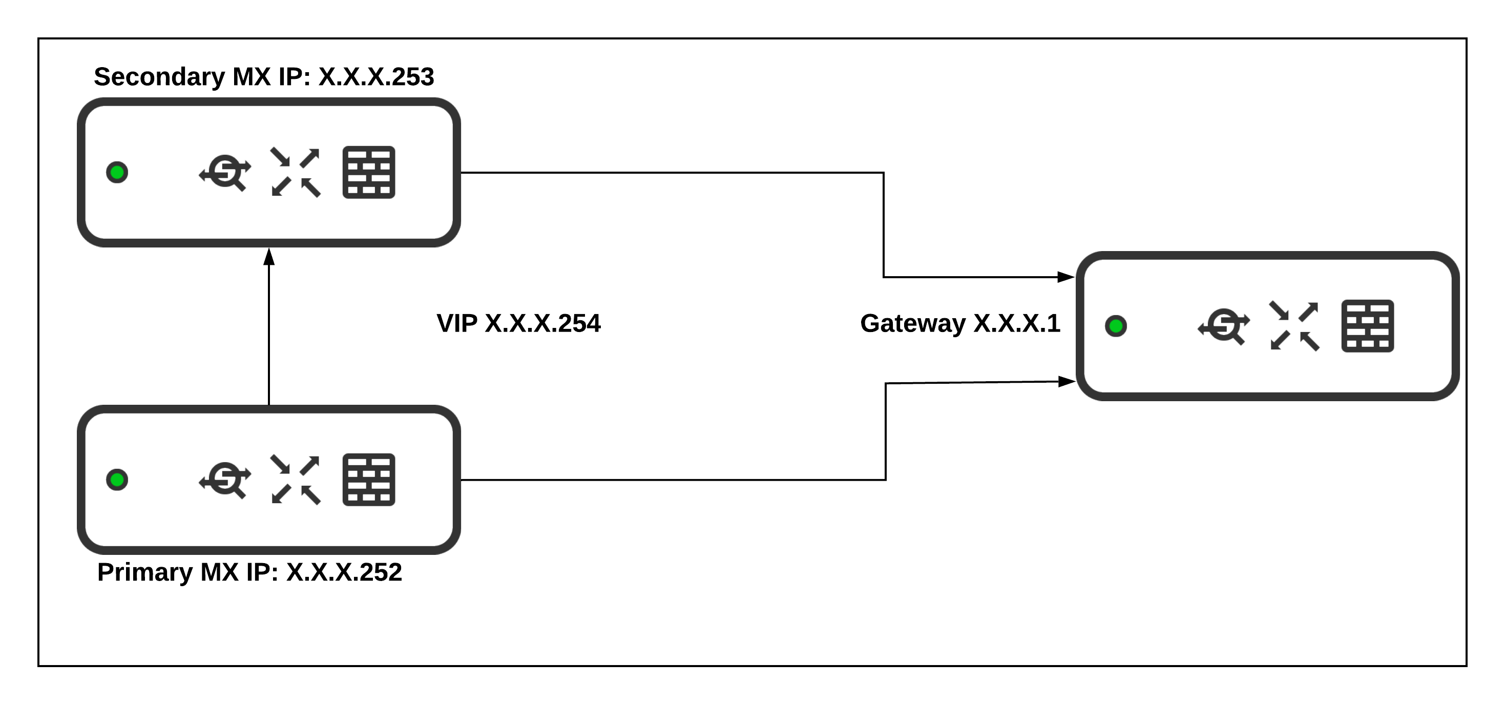
WAN Appliance VPN Concentrator - Virtual IP Assignment
The virtual IP address (VIP) is shared by both the primary and warm spare VPN concentrator. VPN traffic is sent to the VIP rather than the physical IP addresses of the individual concentrators. The virtual IP is configured by navigating to Security & SD-WAN > Monitor >Appliance status when a warm spare is configured. It must be in the same subnet as the IP addresses of both appliances, and it must be unique. It cannot be the same as either the primary or warm spare's IP address.
The two concentrators share health information over the network via the VRRP protocol. Failure detection does not depend on connectivity to the Internet/Meraki dashboard.
WAN Appliance VPN Concentrator - Failure Detection
In the event that the primary unit fails, the warm spare will assume the primary role until the original primary is back online. When the primary VPN concentrator is back online and the spare begins receiving VRRP heartbeats again, the warm spare concentrator will relinquish the active role back to the primary concentrator. The total time for failure detection, failover to the warm spare concentrator, and ability to start processing VPN packets is typically less than 30 seconds.
WAN Appliance Warm Spare Alerting
There are a number of options available in the Meraki dashboard for email alerts to be sent when certain network or device events occur, such as when a warm spare transition occurs. This is a recommended configuration option and allows a network administrator to be informed in the event of a failover.
The event, “A warm spare failover occurs,” sends an email if the primary WAN Appliance of a High Availability pair fails over to the spare, or vice-versa.
This alert and others, can be referenced in our article on Configuring Network Alerts in Dashboard.
If you are having difficulties getting warm spare to function as expected, please refer to our MX Warm Spare - High Availability Pair document.
HW Redundancy in NAT mode
WAN Appliance NAT Mode – Warm Spare
WAN Appliance NAT Mode Warm Spare is used to provide redundancy for internet connectivity and appliance services when a WAN Appliance is being used as a NAT gateway.
WAN Appliance NAT Mode - Warm Spare Setup
In NAT mode, the units in the HA pair are connected to the ISP or ISPs via their respective Internet ports, and the internal networks are connected via the LAN ports.
WAN configuration: Each appliance must have its own IP address to exchange management traffic with the Meraki cloud. If the primary appliance is using a secondary uplink, the secondary uplink should also be in place on the warm spare. A shared virtual IP, while not required, will significantly reduce the impact of a failover on clients whose traffic is passing through the appliance. Virtual IPs can be configured for both uplinks.
LAN configuration: LAN IP addresses are configured based on the Appliance IPs in any configured VLANs. No virtual IPs are required on the LAN.
Additional warm spare configuration details can be found in our article, MX Warm Spare - High Availability Pair.
WAN Appliance NAT Mode - Virtual IP Assignment
Virtual IP addresses (vPs) are shared by both the primary and warm spare appliance. Inbound and outbound traffic uses this address to maintain the same IP address during a failover to reduce disruption. The virtual IPs are configured on the Security & SD-WAN > Monitor > Appliance status page. If two uplinks are configured, a vIP can be configured for each uplink. Each vIP must be in the same subnet as the IP addresses of the appliance uplink it is configured for, and it must be unique. It cannot be the same as either the primary or warm spare's IP address.
WAN Appliance NAT Mode - Failure Detection
There are two failure detection methods for NAT mode warm spare. Failure detection does not depend on connectivity to the Internet / Meraki dashboard.
WAN Failover: WAN monitoring is performed using the same internet connectivity tests that are used for uplink failover. If the primary appliance does not have a valid Internet connection based on these tests, it will stop sending VRRP heartbeats which will result in a failover. When uplink connectivity on the original primary appliance is restored and the warm spare begins receiving VRRP heartbeats again, it will relinquish the active role back to the primary appliance.
LAN Failover: The two appliances share health information over the network via the VRRP protocol. These VRRP heartbeats occur at layer 2 and are performed on all configured VLANs. If no advertisements reach the spare on any VLAN, it will trigger a failover. When the warm spare begins receiving VRRP heartbeats again, it will relinquish the active role back to the primary appliance.
WAN Appliance NAT Mode – DHCP Synchronisation
The WAN Appliances in a NAT mode high availability pair exchange DHCP state information over the LAN. This prevents a DHCP IP address from being handed out to a client after a failover if it has already been assigned to another client prior to the failover.
DC-DC Failover - Hub/Data Center Redundancy (Disaster Recovery)
Meraki's WAN Appliance Datacenter Redundancy (DC-DC Failover) allows for network traffic sent across Auto VPN to failover between multiple geographically distributed datacenters.
DC Failover Architecture
A DC-DC failover architecture is as follows:
-
One-armed VPN concentrators or NAT mode concentrators in each DC
-
A subnet(s) or static route(s) advertised by two or more concentrators
-
Hub & Spoke or VPN Mesh topology
-
Split or full tunnel configuration
Operation and Failover
Deploying one or more WAN Appliances to act as VPN concentrators in additional data centers provides greater redundancy for critical network services. In a dual- or multi-datacenter configuration, identical subnets are advertised from each datacenter with a VPN concentrator mode WAN Appliance.
In a DC-DC failover design, a remote site will form VPN tunnels to all configured VPN hubs for the network. For subnets that are unique to a particular hub, traffic will be routed directly to that hub. For subnets that are advertised from multiple hubs, spoke sites will send traffic to the highest priority hub that is reachable.
When a WAN Appliance is configured to connect to multiple VPN concentrators advertising the same subnets, the routes to those subnets become tracked. Hello messages are periodically sent across the tunnels from the remote site to the VPN hubs to monitor connectivity. If the tunnel to the highest priority hub goes down, the route is removed from the route table and traffic is routed to the next highest priority hub that is reachable. This route failover operation only applies when identical routes are advertised from multiple Auto VPN hubs.
Concentrator Priority
When multiple VPN hubs are configured for an organization, the concentrator priority can be configured for the organization. This concentrator priority setting determines the order in which VPN mesh peers will prefer to connect to subnets advertised by multiple VPN concentrators.
This setting does not apply to remote sites configured as VPN spokes.
Other Datacenter Considerations
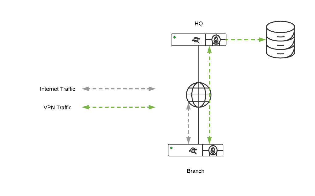
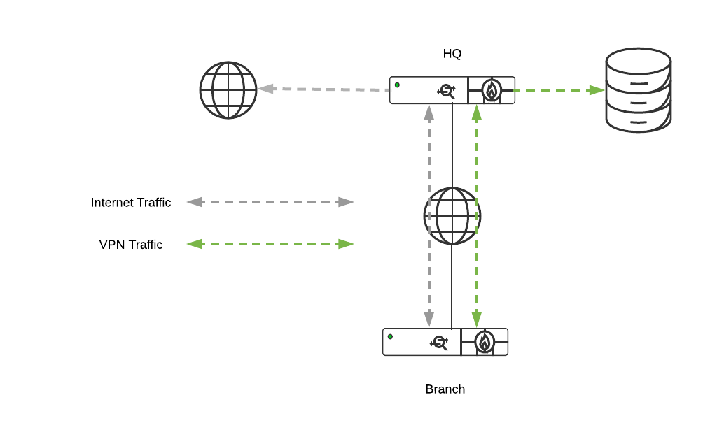
When implementing an DC-DC architecture, a warm spare concentrator configuration (see warm spare section above) and OSPF route advertisement should always be taken into consideration for WAN Appliances acting as VPN concentrators in a datacenter. Additionally, route flow logic should be considered for all applications in the deployment environment to ensure availability requirements are met. To assist with better understanding DC-initiated flows, please refer below.
Supported VPN Architectures
VPN Topologies
There are several options available for the structure of the VPN deployment.
Split Tunnel
In this configuration, branches will only send traffic across the VPN if it is destined for a specific subnet that is being advertised by another WAN Appliance in the same dashboard organization. The remaining traffic will be checked against other available routes, such as static LAN routes and third-party VPN routes, and if not matched will be NATed and sent out from the branch WAN Appliance unencrypted.
Full Tunnel
In full tunnel mode all traffic that the branch or remote office does not have another route to is sent to a VPN hub.
Hub and Spoke
In a hub and spoke configuration, the WAN appliances at the branches and remote offices connect directly to specific WAN Appliances and will not form tunnels to other WAN Appliance or Teleworker devices in the organization. Communication between branch sites or remote offices is available through the configured VPN hubs. This is the recommended VPN topology for most SD-WAN deployments.
-
Hub and Spoke - Total Tunnel Count

Where H is the number of hubs, S is the number of spokes and L is the number of uplinks the WAN Appliance has (LH for the hubs, LS for the spokes). If each WAN Appliance has a different number of uplinks then a sum series, as opposed to a multiplication will be required.
For example, if all WAN Appliances have 2 uplinks, we have 4 hubs and 100 spokes, then the total number of VPN tunnels would be 24 + 1600 = 1624.
Standard Hub & Spoke
How it works:
Utilizing the standard Meraki Auto VPN registry to ascertain how the VPN tunnels configured need to form (i.e. via public address space or via private interface address space) as described in Configuring Site-to-site VPN over MPLS.
When should it be used?
Whenever possible. It is strongly recommended that this model is the 1st, 2nd and 3rd option when designing a network. Only if the deployment has an exceptionally strong requirement should one of the following hub and spoke derivatives be considered.
VPN Mesh
It is also possible to use a VPN mesh configuration in an SD-WAN deployment.
In a mesh configuration, a WAN Appliance at the branch or remote office is configured to connect directly to any other WAN Appliances in the organization that are also in mesh mode, as well as any spoke WAN Appliances that are configured to use it as a hub.
-
Full Mesh - Total Tunnel Count
Where H is the number of WAN Appliances and L is the number of uplinks each WAN Appliance has.
For example, if all WAN Appliances have 2 uplinks and there are 50 WAN Appliances, then the total number of VPN tunnels would be 4900 and every WAN Appliance would have to be able to support 196 tunnels from the number of VPN peers for a single WAN Appliance (49) multiplied by the number of VPN tunnels between each peer (4), in this case, we would need 50 MX100s as a minimum.
China Auto VPN
With regulatory constraints imposed by the Chinese government, specific architecture requirements are needed to deploy and interconnect the Auto VPN domain within China to the rest of the world.
Secure VPN technology provides the most cost-effective connectivity under most circumstances. Chinese regulations have placed restrictions affecting VPN technologies across international borders. For enterprises to achieve cross border connections, there are two options.
-
The enterprise can directly lease international dedicated lines from the 3 Chinese telecom carriers (China Telecom, China Mobile, China Unicom) in China.
-
Additionally, the enterprise can directly delegate a foreign telecom carrier with a presence in China to rent the international dedicated line (including VPN) from the 3 Chinese telecom carriers, and connect the corporate private network and equipment.
Note: The above cross-border connection methods must be used only for internal data exchange and office use. (Current as of 3 February 2018, subject to further regulatory developments.)
All devices located within mainland China will connect to Meraki China servers also located within China. Currently, only enterprise licensing is available for WAN Appliances located within China.
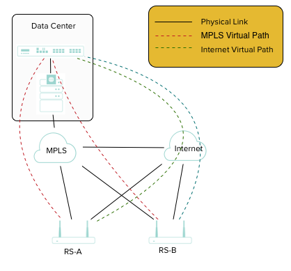
China Auto VPN Architecture
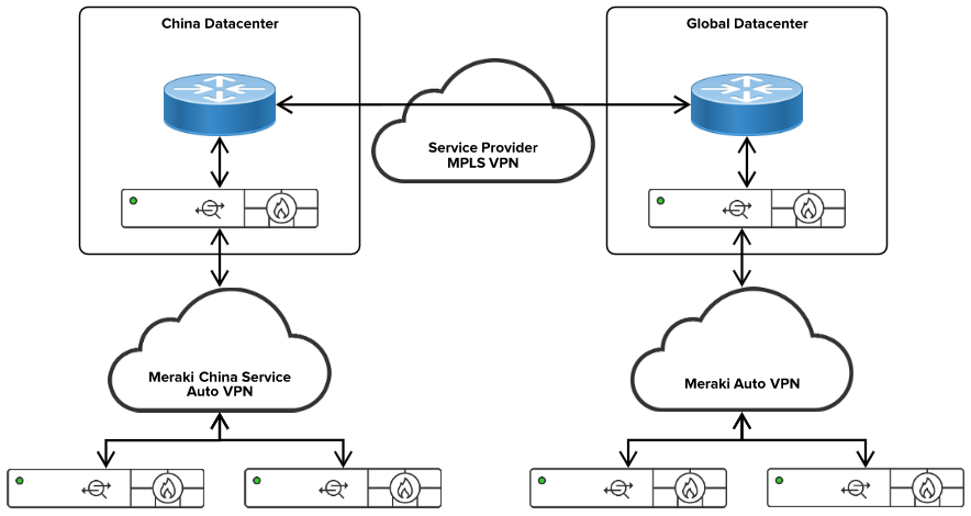
In the above diagram, we are utilizing Meraki Auto VPN to connect the enterprise sites inside China. The above diagram also demonstrates the Chinese government-approved dedicated circuits connecting the Chinese parts of the enterprise to the rest of the global enterprise. Dynamic routing such as BGP or OSPF can be utilized to exchange routing information between the domains.