General MX Best Practices
With the increasing popularity and demand for SD-WAN architecture, planning and designing a secure and highly functional network can be a challenging task. With cloud technology on the rise, and an increase in the amount of user data in modern networks, it is no easy task to plan and accommodate, while maintaining overall security. The Cisco Meraki WAN appliances allow for high-end performance with a robust feature set to provide an easy to manage security solution for environments of any size. From small form factor teleworker gateways to powerful datacenter appliances, the Cisco Meraki WAN appliance allows for flexibility and functionality of network operations.
For branch offices that require communication to the corporate network, remote employees on the go that need to view important documents on public networks, or administrators that require increased control over client devices, Software Defined Networking is an ever-growing key component of the modern data network. Typically this requires tedious interaction and configurations to ensure full functionality for end users and client devices, as well as constant monitoring. Due to the fact that Cisco Meraki WAN appliances are managed completely with the Meraki cloud, all of this can be done with our intuitive online dashboard. The dashboard provides the in-depth visibility needed for the modern network with integrated monitoring tools.
To find more in-depth information on what model of the Cisco Meraki WAN appliance best suits your needs, please refer to the MX sizing guide.
Deployment Options
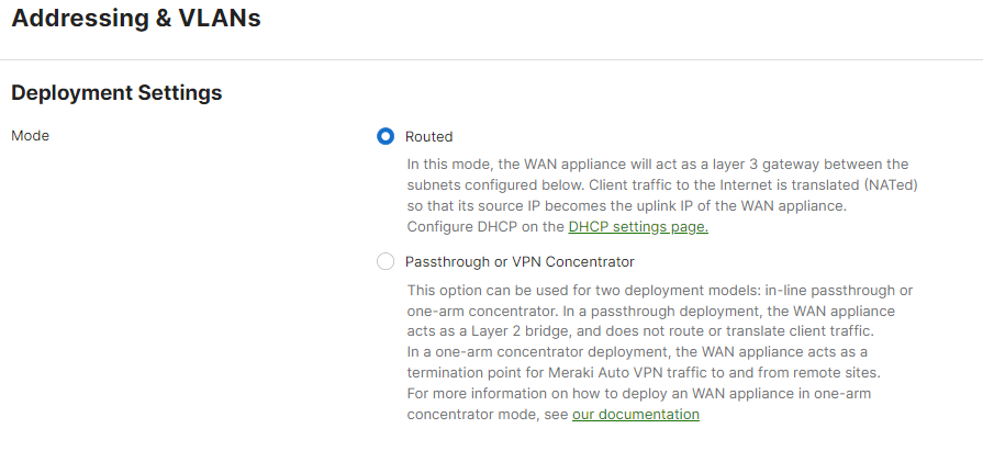
The Cisco Meraki WAN appliance has a number of deployment options to meet the needs of your network and infrastructure. Whether as the main edge firewall for your network, or as a concentrator device in your data center, the WAN appliance can be easily integrated. The operational modes of the WAN appliance can be found on the Cisco Meraki dashboard under Security & SD-WAN > Configure > Addressing and VLANs.
Routed (NAT) Mode
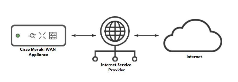
Routed mode on a Cisco Meraki WAN appliance is best used when the WAN appliance will be connecting directly to your internet demarcation point. When this is the case, the WAN appliance will have a public IP address that is issued by the internet service provider. The WAN appliance will also be the device handling the routing for clients to the internet, and any other networks configured for the device to communicate to. This mode is optimal for networking environments that require a WAN appliance with Layer 3 networking capabilities.
NAT Mode Features
|
|
NAT Mode Considerations
- A Cisco Meraki WAN appliance operating in NAT mode is best deployed when its WAN connection is directly connected to the ISP handoff.
- When in NAT mode, The Cisco Meraki WAN appliance can provide Layer 3 (L3) functions such as NAT or routing since it has Internal LAN subnets and VLAN Interfaces. Check section "Addressing and VLANs" for more information about Internal LAN subnets and VLAN Interfaces.
- A WAN appliance can operate in NAT mode if it is behind another Layer 3 device that is also performing NAT, but you may run into complications with Meraki cloud connectivity, as well as some features such as Meraki Auto VPN.
Passthrough or VPN Concentrator Mode
Passthrough mode on a Cisco Meraki WAN appliance configures the appliance as a Layer 2 bridge for the network. The WAN appliance in this mode will not perform any routing or any network translations for clients on the network. Passthrough or VPN Concentrator Mode is best used when there is an existing Layer 3 device upstream handling network routing functions. The WAN appliance in this instance would still act as a WAN appliance, but with less functionality for Layer 3 networking.
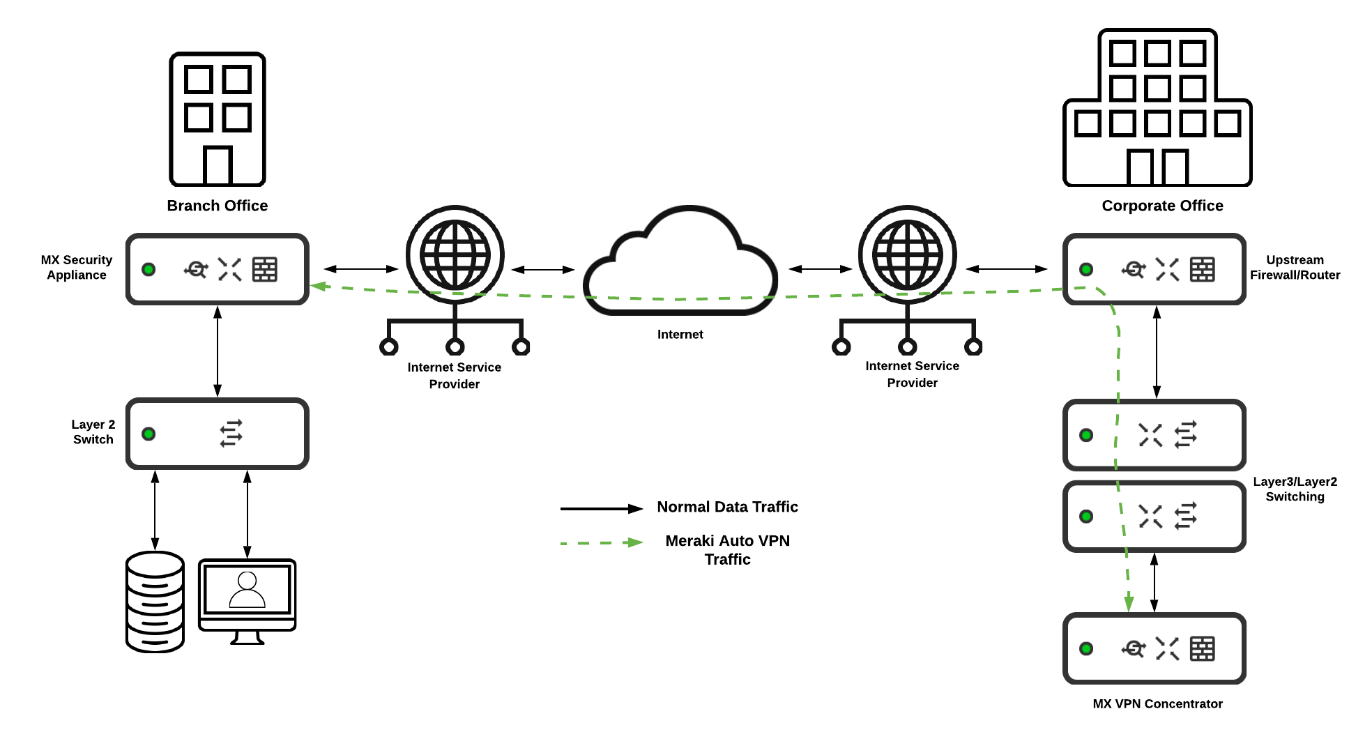
The recommended use case for the WAN appliance in passthrough mode is when it is acting as a VPN Concentrator for the Cisco Meraki Auto VPN feature. Passthrough or VPN Concentrator mode ensures easy integration into an existing network that may already have layer 3 functionality and edge security in place. With this mode, a Cisco Meraki WAN appliance can be integrated into the existing topology and allow for seamless site to site communication with minimal configuration needed.
Passthrough or VPN Concentrator Mode Features
* Advanced Security License or SD-WAN+ License required
** It is not recommended to use this feature while configured in Passthrough/Concentrator mode
Passthrough or VPN Concentrator Considerations
- When in Passthrough or VPN Concentrator mode, The Cisco Meraki WAN appliance will not provide Internal LAN subnets and VLAN Interfaces performing Layer 3 (L3) functions such as NAT or routing.
- A WAN appliance in passthrough or VPN concentrator mode will act as a layer 2 firewall that will integrate into the existing LAN with a layer 3 routing appliance upstream.
- VPN destined traffic will need to be directed to the WAN appliance for effective routing to the VPN endpoint. As such, static routes on other Layer 3 capable devices may be needed for full VPN functionality.
- WAN appliances in passthrough are able to allow IPv6 traffic to pass across the existing LAN if the traffic flows through the WAN appliance.
Redundancy and High Availability
With the network being a vital tool and resource for today's business operations, it is essential that network functionality and connectivity remain as consistent as possible. Planning for high availability in your network infrastructure is critical. Cisco Meraki WAN appliances allow for easy and seamless configuration and design of a highly available network. To ensure the maximum amount of uptime for your network, WAN appliances include a number of capabilities for a redundant design. These capabilities include the ability to form a High Availability (HA) pair, as well as multiple internet uplink ports with automatic failover functionality.
High Availability and Redundant WAN Connections
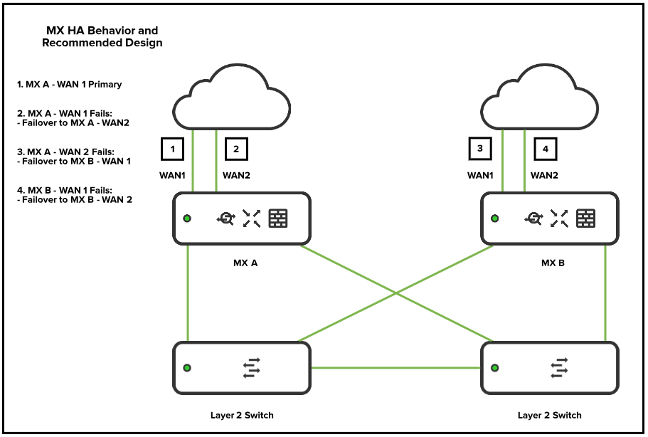
The recommended deployment to ensure the most possible uptime is an environment that combines two high availability paired WAN Appliances with multiple Internet Service Provider connections. In this architecture, there is full redundancy to minimize the possible downtime in the event of a failure in either an appliance or a service provider.
High Availability (HA) Pair
When deploying two WAN appliances in high availability (HA), it is recommended to have the management traffic for HA traverse via a downstream connection to a layer 2 switch, and to not have a dedicated HA cable connected between the two appliances. The reason for this is because there is an increased potential for a spanning-tree loop if the WAN appliances are also connected to the same layer 2 switch. The best topology is to have the WAN appliances connected to the same downstream Layer 2 switch.
.png?revision=1&size=bestfit&width=758&height=487)
NOTE: The WAN appliance generates and sends VRRP heartbeats across all configured VLANs. For best high availability behavior, it is recommended to have all VLANs allowed on the downstream connections to the switches that are connecting the WAN appliance HA pair. It is also recommended that any downstream switches that may be passing the VRRP traffic are configured to be aware of all the VLANs configured on the WAN appliance.
For more information on HA configuration with VRRP on the Meraki WAN appliance, see the knowledge base document MX Warm Spare - HA Pair.
For more information on WAN appliance layer 2 connectivity, see the knowledge base document MX Layer 2 Functionality.
Cisco Meraki WAN Appliance Networking
When planning and designing a network, an important consideration is whether the client and end-user devices should be on the same network or subnet. In most cases, having multiple subnets in your deployment is recommended, as it adds a layer of security against potentially malicious devices or users. This is especially recommended if you are planning on having a guest network set up. The Meraki WAN appliance is capable of supporting multiple subnets or VLANs so the user networks can be separated out.
Addressing and VLANs
The best practice for planning and configuring a network is to have multiple VLANs for different traffic uses cases. This is especially recommended for separation of networks that will be hosting employee data and networks providing guest access. This is a critical consideration to ensure the maximum possible security for your networking environment. Using multiple VLANs for different use cases will also decrease the amount of broadcast traffic within the same subnet. When designing and configuring multiple VLANs, it is generally recommended to create the subnet to be sized for the necessary amount of devices intended to be in that particular network. Generally, networks with /24 subnet masks are large enough for common deployments, while also providing room for expansion and simple subnetting scalability if more VLANs are to be added. However, it is always best to consider the needs of your deployment when planning your subnets, as some deployments may require larger addressing spaces.
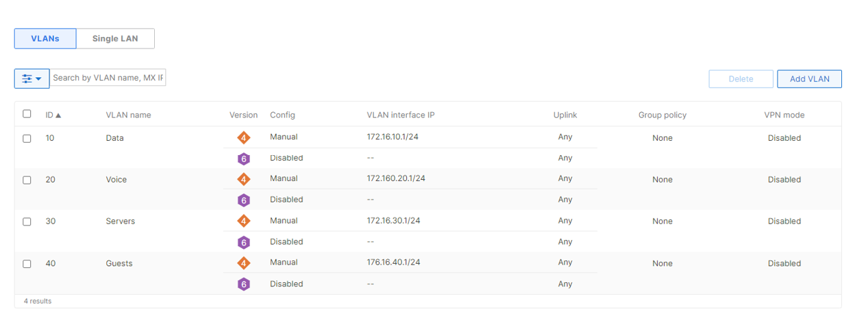
For more information on enabling and configuring VLANs please see our knowledge base document Configuring VLANs on the MX Security Appliance.
Routing and Layer 3 Connectivity
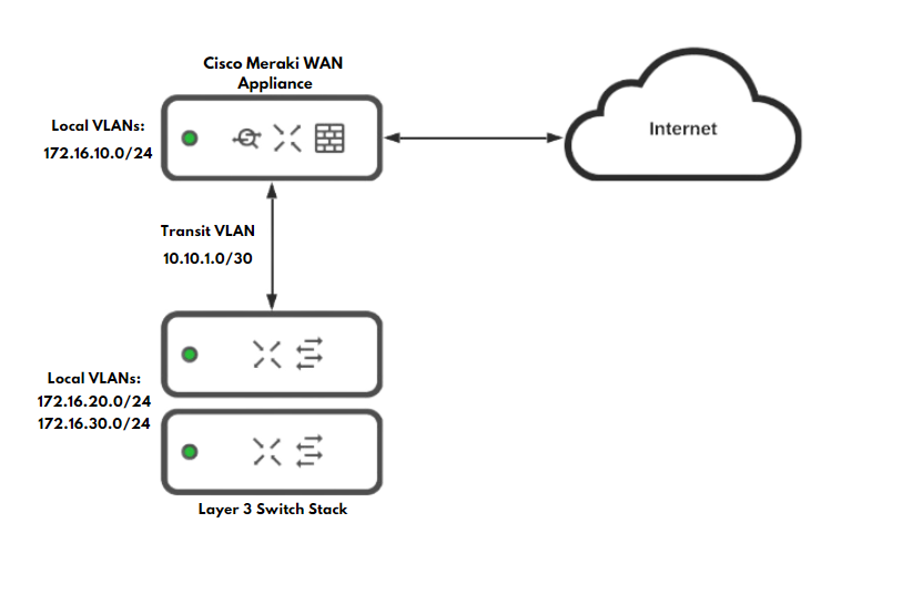
In certain deployments, the Meraki WAN appliance may not be the only device performing layer 3 functions for the entirety of the data network. Examples of this can be a deployment where the WAN appliance acts as the internet edge gateway while layer 3 routing is performed on downstream devices, or where another layer 3 capable device is added into the existing routing topology. If this is the case, then the WAN appliance must have static routes configured to allow for effective communication to the other layer 3 destinations in the network. The other layer 3 devices must also have static routes in place to the WAN appliance.
In the example below, an WAN appliance is set up as an Internet edge firewall, with the rest of the layer 3 routing taking place on a downstream switch stack. With this configuration, it is best to have a single subnet configured between the WAN appliance and the other layer 3 device, to minimize the amount of traffic and routing that will be taking place as well as to keep routing consistency. This single subnet will act as a transit VLAN for all routing that is to take place between the two layer 3 endpoints in the topology.
For more information on WAN appliance routing and layer 3 connectivity, please refer to the documents MX and MS Basic Layer 3 Topology and MX Routing Behavior
WAN Appliance Security Functionality
The Meraki WAN appliance allows for simple yet effective security for your networks and deployments with the numerous security functions it has to offer. Configuring advanced security policies and features ensures a protected environment for your deployment. The WAN appliance has the following services and configuration options for security functionality:
- Layer 3 Stateful Firewall
- Layer 7 Firewall functionality
- Port Forwarding and NAT
- Advanced Malware Protection (Advanced Security License)
- Intrusion Detection and Prevention Services (Advanced Security License)
- IP Source Address Spoofing Protection
Layer 3 Firewall Rules
The Meraki WAN appliance allows for custom outbound firewall rules to be configured to ensure precise and granular control over which networks are able to communicate with one another. The WAN appliance is a stateful firewall, meaning that all inbound connections are blocked unless they have either originated from within the WAN Appliance or a forwarding rule is configured.
By default, all VLANs configured on the WAN appliance will be able to communicate with one another. If there are VLANs you wish to not be able to pass traffic between, firewall rules will need to be configured. It is best practice to restrict the amount of traffic that can travel between subnets that are not closely related. For example, it is recommended to create firewall rules to block all traffic from a VLAN that may be used for guest access from being able to contact other VLANs used for business operations.

Additionally, if there are internal users that need internet access, but should be blocked from accessing a certain site or IP address, the firewall rules can be configured with IPs or URLs as the destinations. The use case for this is if you know of a website the users in that VLAN should not access.

NOTE: The layer 3 firewall rules configured will be processed in top-down order. If traffic matches a rule in the list, the WAN appliance will no longer process any further rules for that traffic.
Layer 7 Firewall Rules
Best practice design for Layer 7 rules is to ensure that the category you have selected to block does not fall under the traffic flow for applications you may use. For example, if you choose to block the category for "File Sharing," and you block all options, you may cause a disruption in service for an application such as Microsoft OneDrive. It is best to try and configure Layer 7 rules as granular as possible, to avoid such scenarios.
Using Layer 7 firewall rules for blocking traffic based on countries also has its caveats as well. While it may seem more secure to block all countries other than the one the WAN appliance is located in, this can cause issues with traffic flows to certain resources that may actually be necessary for daily operations. Certain webpages and web applications can be hosted in a country not being blocked, but they may pull supplementary data or resources from a server located in a country that is being blocked by the WAN appliance. As a result, certain aspects may not function as intended or may fail to function altogether. It is essential to only block countries with a Layer 7 rule if you know traffic from this country is malicious in nature.
For more information on WAN appliance layer 7 rules please refer to the knowledge base documents for the MX Firewall Settings and Creating a Layer 7 Firewall Rule
Port Forwarding and NAT Rules
Due to the nature of the Cisco Meraki WAN appliance, all inbound traffic that did not originate from within the networks configured on the appliance will be dropped by default. This is because the Meraki WAN appliance is a stateful firewall, so the WAN appliance must be aware of or expecting incoming traffic. For connections that originate from outside of the WAN appliance and need to be allowed in, either a port forwarding rule or a NAT rule can be configured to permit this traffic.
Port Forwarding Rules
It is important to plan out your port forwarding rules accordingly with the traffic you are planning to let in behind the firewall. The best configuration for port forwarding rules is to plan for as narrow of a scope as possible. Only create port forwarding rules for subsequent connections on ports that are necessary. It is also not recommended to create port forwarding rules with "Any" for the allowed remote IP ranges. The appropriate use-case for having the parameter "Any" in the allowed remote IP field is if you have a web server behind the WAN appliance. If a web server is in use for the port forwarding rule, it is best to use an obscure port range for the public ports configured, as common web ports can lead to potential vulnerabilities.

1:1 and 1:Many NAT Rules
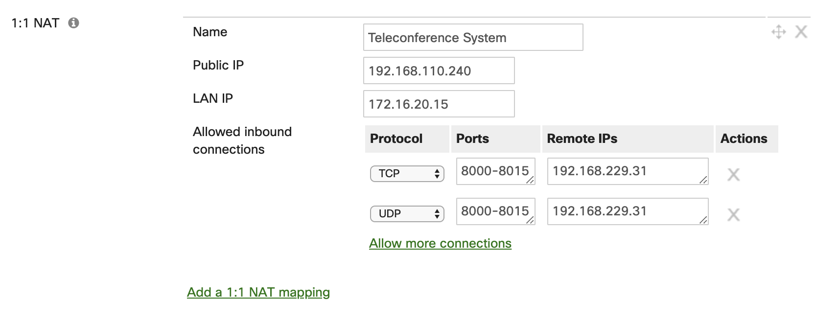
A 1:1 rule enables traffic destined for a particular public IP address to be forwarded to a particular internal host or hosts. This is similar in nature to a port forward, but in this case the traffic is being sent to another public IP address that is not the IP of the WAN appliance WAN interface. This is best used when there are multiple public IP addresses available, and you do not wish to have internet-based traffic for a web server destined to the public IP of the WAN interface on the WAN appliance. If a 1:1 NAT rule is configured for other services that are not for a web facing server, then it is best practices to limit the range of ports being used, as well as the range of remote IPs for the connection.

1:Many NAT Rules
In some instances, particularly if the number of public IPs available to you are limited, a 1:Many NAT rule can be put in place. This is also very similar to a port forwarding rule, but again the public IP address that traffic is destined to determines how the Cisco Meraki WAN appliance handles the traffic. If traffic destined for that specific IP address comes in on a particular public port, then the WAN appliance will forward the traffic to an internal host based on said port. This enables the ability to use a single public IP address for multiple services. This also allows for a concise deployment so there are not multiple public IPs required.

Advanced Malware Protection (AMP)
Advanced Malware Protection (AMP) is an adaptive and powerful tool that is incorporated on the Cisco Meraki WAN appliance with the Advanced Security license. AMP scans and inspects HTTP downloads that are moving through the WAN appliance. The WAN appliance then takes action based on the threat intelligence it receives from the AMP cloud. If a download matches a known signature from the AMP cloud, then the WAN appliance will block the download. With a WAN appliance, it is highly recommended to have AMP enabled and functioning so your networking environment is secure and safe from attacks.
For more information about AMP, please refer to the knowledge base documents Advanced Malware Protection (AMP) and Threat Protection
Intrusion Detection and Prevention (IDS/IPS)
With the Advanced Security license, Intrusion Detection and Prevention (IDS/IPS) enables the Meraki WAN appliance to inspect all incoming and outgoing traffic that is being routed internally and externally in the networking environment. IDS/IPS searches for various signature-based attacks as traffic flows through the WAN appliance. This is achieved with the various rules and signatures that are in the SNORT® intrusion detection engine. This enables the WAN appliance to detect malicious traffic and not only provides alerts that a known signature was detected, but also take action against that threat and prevent it from doing harm on the network. To ensure a secure and stable networking environment, it is recommended to have Intrusion Detection and Prevention services enabled and operating on the WAN appliance.
For more information on IDS/IPS, please refer to the knowledge base document Threat Protection
IP Source Address Spoofing Protection
IP Source Address Spoofing Protection is a security mechanism on the Cisco Meraki WAN appliance that enables protection from malicious users on the network from impersonating other hosts and attempting to bypass security restrictions. The WAN appliance uses several methods of traffic verification to ensure client data is authentic and not spoofed by a malicious attacker. It is recommended to have this feature set to the mode "Block" so malicious IP spoofing events are mitigated on the network by the WAN appliance as soon as they are identified. There is the option to have the mode set to "Log" but this will not provide protection against these types of attacks, but rather just alert that malicious traffic of this nature has been detected.

If you would like more information about this feature on the Meraki WAN appliance, please see the knowledge document IP Source Address Spoofing Protection
Site to Site VPN
When connectivity and intercommunication is needed between different networks that are separated geographically, a site to site VPN tunnel is the best solution. The Meraki WAN appliance is equipped with all the necessary functionality for VPN tunnel communication between sites and networks. The SD-WAN capabilities of the WAN appliance allow for other WAN appliances in the same Cisco Meraki organization to easily establish VPN tunnels to one another with a quick and simple configuration. This is achieved with the Cisco Meraki Auto VPN.
Meraki Auto VPN
The Meraki WAN appliance allows for simple and seamless integration and configuration of VPN tunnels among sites. This is achieved with Meraki's proprietary Auto VPN functionality that allows for simple and fast configuration of site to site VPN tunnels. Additionally, Auto VPN enables maximum uptime of the site-to-site tunnels with congruent VPN tunnels on all available WAN interfaces. VPN tunnels are built actively on all WAN interfaces on the WAN appliance that can reach the Meraki cloud. This allows for dynamic failover and built-in redundancy with no extra configuration needed. It is recommended to use Meraki Auto VPN between WAN appliances for essential inter-site communication. Note that Auto VPN can only be used for Meraki to Meraki communications, for Meraki devices in the same Meraki dashboard organization. Separate Meraki dashboard organizations generally represent separate SD-WAN environments.

Auto VPN Hub and Spoke Operation
The Auto VPN feature allows an appliance to operate as either a hub or a spoke in the VPN topology. A WAN appliance configured as a hub will build a VPN tunnel to every WAN appliance that is operating as a hub and each spoke that the hub is configured as the hub appliance. Spoke devices will build tunnels only to WAN appliances they have configured as hubs, and not to other spoke sites. It is important to take this behavior into consideration, as configuring each WAN appliance as a spoke can cause a degradation of service in large deployments.
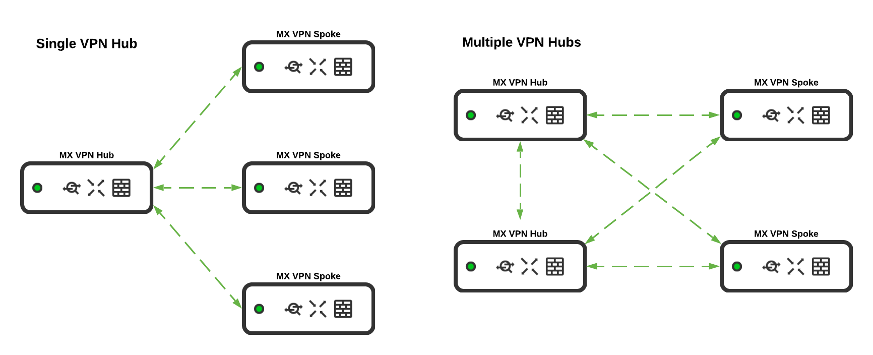
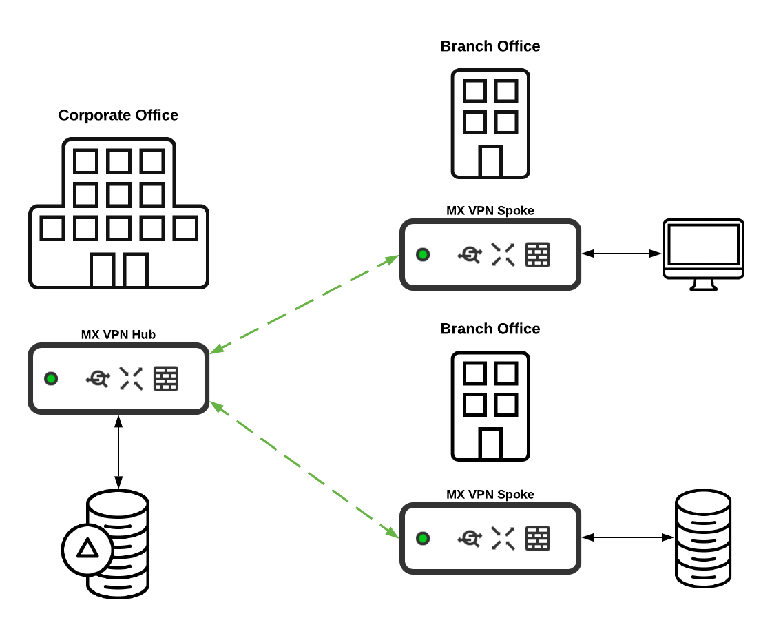
It is recommended to have a Cisco Meraki WAN appliance configured as a hub if it is essential for all other WAN appliances configured in the VPN topology to have communication to networks on the hub appliance. Typically this is effective for WAN appliances at locations where there are a large number of resources for business operations, such as at the corporate office or a datacenter.
Client VPN
The Meraki WAN appliance includes the option to configure client VPN functionality for remote users that require access to resources hosted in your data network. The client VPN feature allows those users to establish a secure connection to the WAN appliance from their device as long as they have a valid internet connection. Though it is not required for full client VPN functionality, the client VPN feature has increased functionality and ease of use when it is deployed with a policy encompassed with Cisco Meraki Systems Manager installed on the user's remote device. Meraki Systems Manager allows for a dynamic policy to be remotely pushed to the client device so the client VPN functionality is seamlessly integrated on the end device without end-user configuration.
It is highly recommended to deploy and use the client VPN feature with the use of a Systems Manager policy, as this allows for a better experience for end-users as they will not have to do any sort of configuration on their end. This is exceedingly useful in the event that the end-user's client VPN service is having issues connecting to the WAN appliance. This allows administrators the ability to effectively troubleshoot the issue without needing the end-user to engage in the technical troubleshooting process; creating a more simple end customer experience.

For more information about the Client VPN feature, please see the following knowledge base documents:
SD-WAN & Traffic Shaping
The Cisco Meraki WAN appliance includes a multitude of built-in SD-WAN functions that are easy to deploy and configure. This allows you to have built-in monitoring and simple configuration with an easy and intuitive interface.
Uplink Configuration
Under the SD-WAN settings, the uplink connections for the WAN appliance can be configured to best fit the needs of your networking environment. The uplink bandwidth limit can be configured and changed to best fit the requirements of the connection with your internet service provider. It is best practice to set the throughput bandwidth to the highest possible amount based on your bandwidth set by your provider as to avoid potentially saturating the connection.
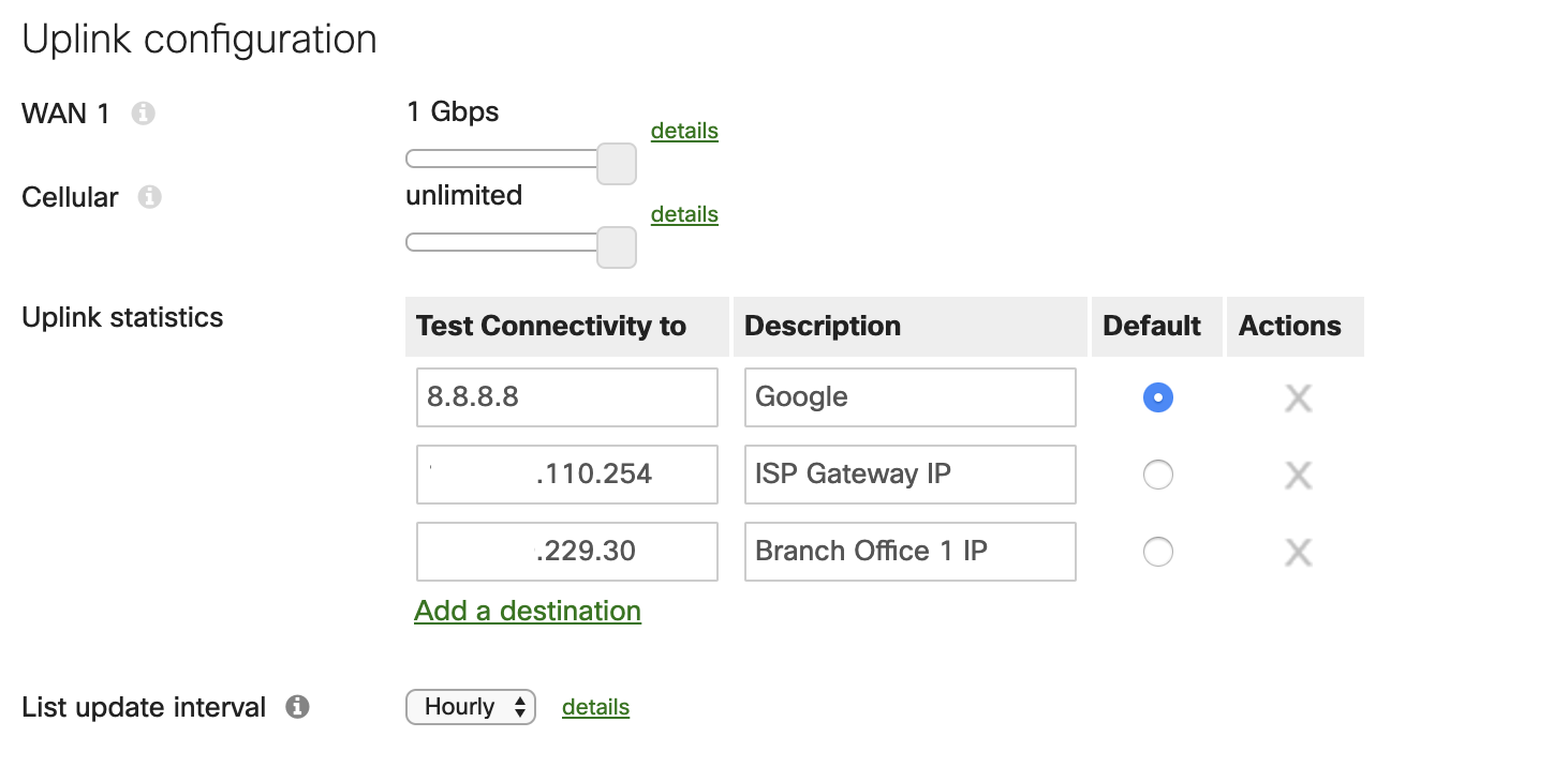
For uplink monitoring, it is recommended to configure multiple uplink statistic test IPs on the Meraki dashboard. This is exceptionally useful for troubleshooting purposes, as it allows the dashboard to collect and monitor data on certain connections specified. A few examples of connections to monitor would be a general connection to the internet (Google's 8.8.8.8 is configured by default), the connection to your service provider gateway, and the connection to any remote sites that may be participating in site to site VPN tunneling.
Another feature of the functionality that the WAN appliance includes is automatic security list updates for features such as AMP, IDS/IPS, and content URL filtering. These lists can be configured to check for changes in security rules on an hourly, daily, or weekly basis. The best practice to ensure your environment stays secure is to have this interval set to check the security lists hourly. The frequency of updates can be changed per each WAN uplink, including the cellular uplink as well.
Uplink Selection
Included with the SD-WAN options is the ability to have the WAN appliance route traffic to different uplinks depending on certain scenarios. Uplink selection enables the ability of policy-based routing on the WAN appliance, which uses flow preferences for specific traffic as it heads out the WAN connection. With this tool, it is recommended to have the uplink connections be set to load balance the traffic if applicable. This is best used if there are redundant internet connections that have similar bandwidth capabilities.
With flow preferences based on the source traffic, it is easy to shape traffic to best fit the nature of the network traffic as it transverses to the WAN connection. An example of what a flow preference may be used for is guest traffic. To allow for a consistent and stable connection the more cost-effective secondary WAN connection can be configured to handle guest related traffic.

SD-WAN Policies
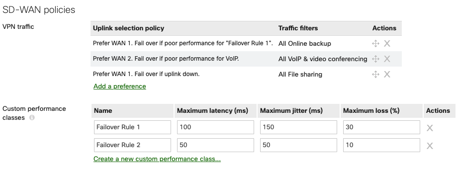
SD-WAN policies can be configured to control and modify the flows for specific VPN traffic. With multiple WAN uplinks, the WAN appliance will proactively build multiple tunnels with each available WAN interface. In the case where there are redundant WAN connections on the WAN appliance, traffic flows based on the type of traffic traversing the VPN connections can also be configured to allow for best performance. Custom policies set to desired preferences can be set to ensure traffic flows take the appropriate path based on your environment. If a WAN connection that normally handles traffic such as file transfers begins to have performance issues, the Cisco Meraki WAN appliance can dynamically change the VPN connection to an alternative WAN uplink. This is done with custom policies or predetermined policies on the dashboard. It is encouraged to configure said policies in your deployment to best fit the needs based on the nature of the traffic and the capabilities of the WAN connections available on the WAN appliance.
This option appears after Multi-Uplink Auto VPN is enabled.
Once configured, these custom VPN policies are enforced on all VPN traffic that matches the specifications you select. Example configurations can be found in the Meraki SD-WAN configuration guide.
If you do have questions about what policies are best for your deployment, you can always reach out to either a Meraki Sales Engineer or your Meraki partner for a consultation on what best fits your needs.
On MX18.2 firmware while using MultiWAN MXs SD-WAN policies and load balancing policies do not apply to WAN3. You can reference MultiWAN_Backup_Uplink
Global Bandwidth Limits
In larger deployments, bandwidth limits for end-user devices can to be put in place to ensure the uplinks do not become saturated. This largely depends on the type of traffic that is seen from users, how many users are on the network, as well as the throughput capabilities of the WAN appliance and the uplinks. With more substantial deployments where there are a large number of clients, it is recommended to set a bandwidth limit on all traffic. The amount of bandwidth required per client can vary depending on the type of traffic seen in the networking environment.
Speedburst is an option to allow clients a short window of time to exceed the bandwidth limit configured to allow, for example, a large file to transfer faster. This is a useful feature if there are users that will be handling and uploading large files frequently on the network. Speedburst is a recommended feature to enable, with the caveat that it should only be used if there are not a large number of clients that will need high amounts of bandwidth at the same time. If there are a select few users or devices that require moments of higher bandwidth then Speedburst is recommended.

Traffic Shaping Rules
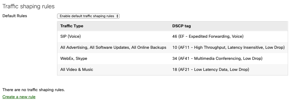
Different types of traffic require different priorities on the network. The WAN appliance is able to prioritize and shape traffic on the local network based on the traffic type. The Meraki dashboard offers default traffic shaping rules that best fit the needs for most deployments. These default rules ensure best performance for local voice traffic, software updates for end client devices, and collaboration applications. It is recommended to enable these default traffic shaping rules on the WAN appliance as it allows for simple and fast configuration for the best performance of network traffic.
