
MT15 Installation Guide - Indoor Air Quality w/CO2
Overview
The Cisco Meraki MT15 is a cloud managed Indoor Air Quality with CO2 Sensor that is exceptionally simple to deploy and configure due to its integration into the Meraki dashboard and the use of BLE technology. The MT family eliminates the complex and costly setups required by traditional solutions which removes the limitations of placement of these sensors.
About this Guide
This guide provides instructions on how to install and configure your MT15 Environmental Sensors.
Product Overview
Physical Specifications
|
Power |
|
|
Operating Environment |
|
|
Hardware |
|
General Purpose Button
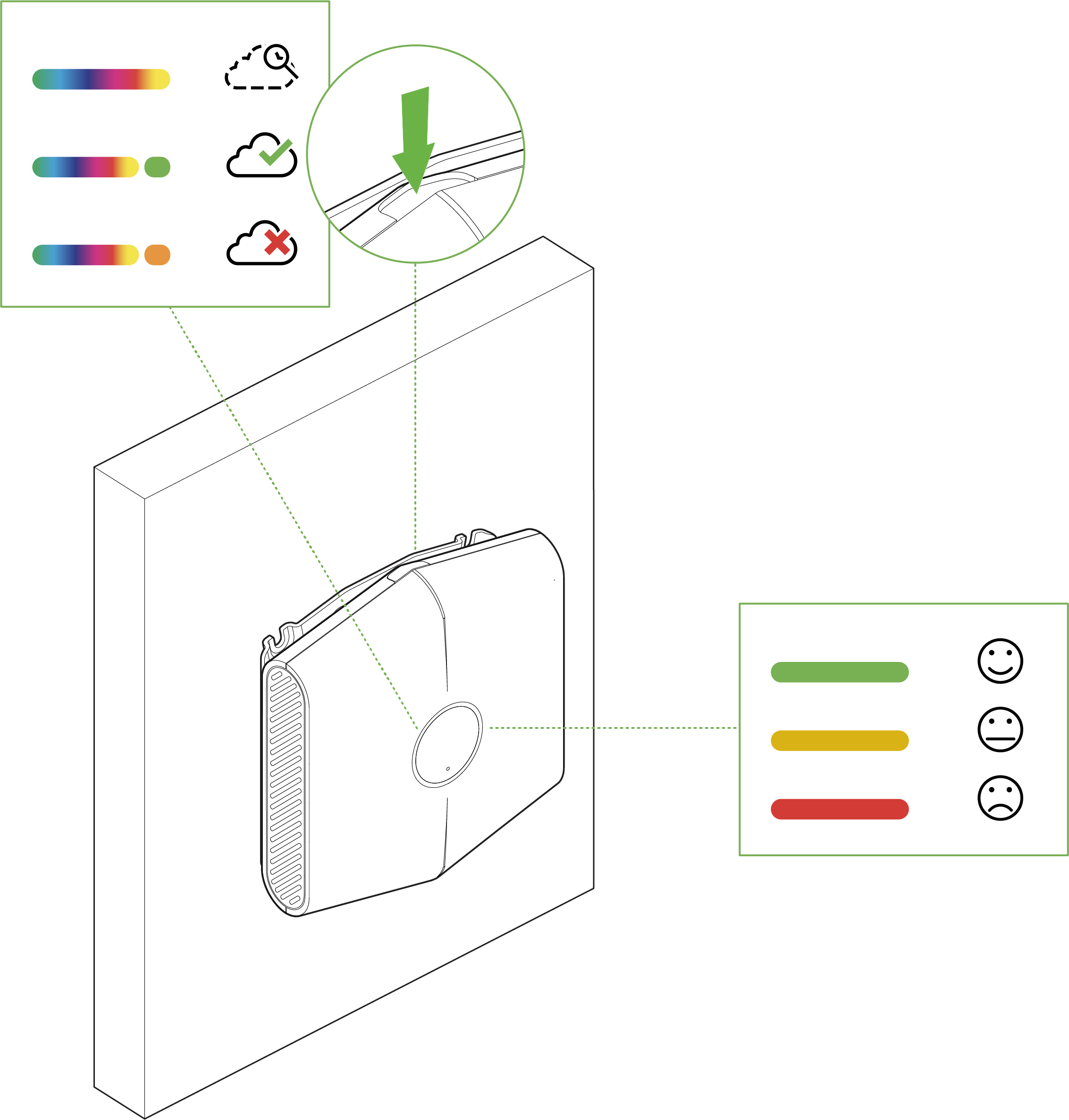
The MT15 has a general purpose button on the top which allows you to wake up the sensor and test if it is able to connect to a gateway.
Multicolor, multifunction LED Ring
MT15 is the first MT Sensor which can visually indicate the conditions of the environment without the use of the Meraki Dashboard. This is done via the LED Ring on the front of the device, which can represent any of the measured metrics and is configurable via the dashboard.
Factory Reset Button
On the back of the sensor, there is a pinhole button to factory reset the sensor. If the button is pressed and held for at least five seconds and then released, the sensor will reboot and it will be restored to its original factory settings by deleting all configuration information stored on the unit.
USB-C Port
The MT15 sensors have a USB-C Port on the back that can be used to provide an alternate source of power using a compatible accessory.
RJ45 Port
The MT15 sensor also has a RJ45 port for PoE on the bottom that can be used to provide an persistent source of power using a PoE switch.
RJ45 and USB-C are ONLY used for Powering the Device. An ethernet link between MT15 and the upstream switch port will NOT be established. An MV or MR Gateway is still required.
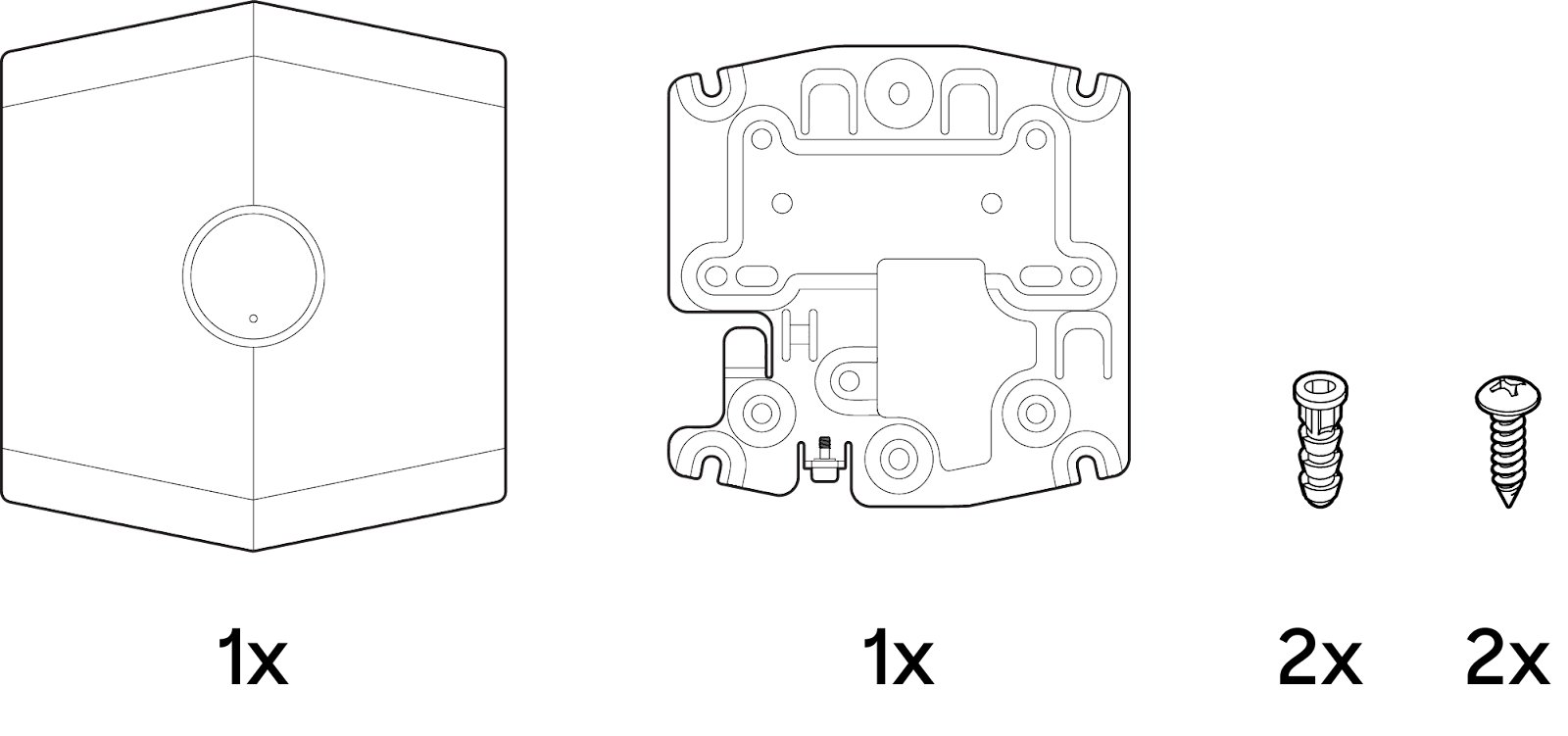
Package Contents
|
Unit |
MT15-HW |
|
Guides |
Quick Install Guide |
|
Mounting equipment |
2x Mounting Screws 2x Drywall Anchors 1x Self-retaining security screw |
Pre-Installation Preparation
You should complete the following steps before going on-site to perform an installation.
Configure Your Network in Dashboard
The following is a brief overview only of the steps required to add an MT15 to your network. For detailed instructions about creating, configuring and managing Meraki Sensor networks, refer to the online documentation (https://documentation.meraki.com/MT).
-
Login to http://dashboard.meraki.com. If this is your first time, create a new account.
-
Find the network to which you plan to add your sensor or create a new network.
-
Add the sensors to your network. You will need your Meraki order number (found on your invoice) or the serial number of each sensor, which looks like Qxxx-xxxx-xxxx, and is found on the back of the unit or included in the box.
-
Add the gateway(MV or MR) to the same network as the sensor.
NOTE: Make sure the gateway is in the same network and is online and operational.
Installation Instructions
General Guidelines
As the MT15 helps monitor the ambient air quality metrics, The following tips and guidelines should be considered when positioning your MT15:
-
Mount the sensor about 6-8 feet from the ground. This will help the sensor monitor the air quality at the average height of human breath.
-
One MT15 has approximately 100 sqft of coverage, meaning at least one MT15 should be installed in every 10x10ft room
-
Make sure the MT15 is away from an inlet or an air vent. Higher air flow near the sensor can result in inaccurate readings.
-
Ensure that the MT15 sensor is oriented in an upright position or flat with the LED ring facing down with a clear path for airflow through the vents (right and left sides).
MT15 should only be mounted on a wall in an upright position or ceiling. Any other orientation will cause inconsistencies in readings.
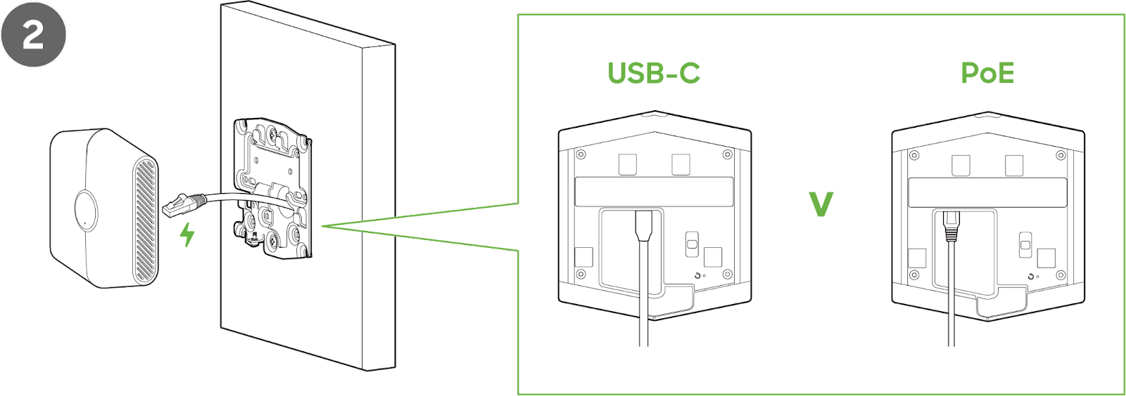
Operating Modes
The MT15 sensors have 2 operating modes:
-
USB-C Powered - Requires a 5V; 0.2A USB-C power adapter to power the sensor.
-
PoE - 802.3af
NOTE: When powered by PoE, a Gateway is still required for MT15, this is for Power Only.
Mounting Instructions
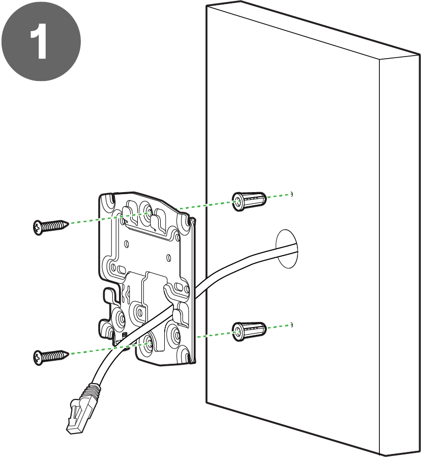
For most mounting scenarios, the MT15 has flexible options to provide quick and simple mounting. The instructions are as follows:
NOTE - It is important to ensure that the sensor is oriented in the correct position for the data collected to be accurate.
-
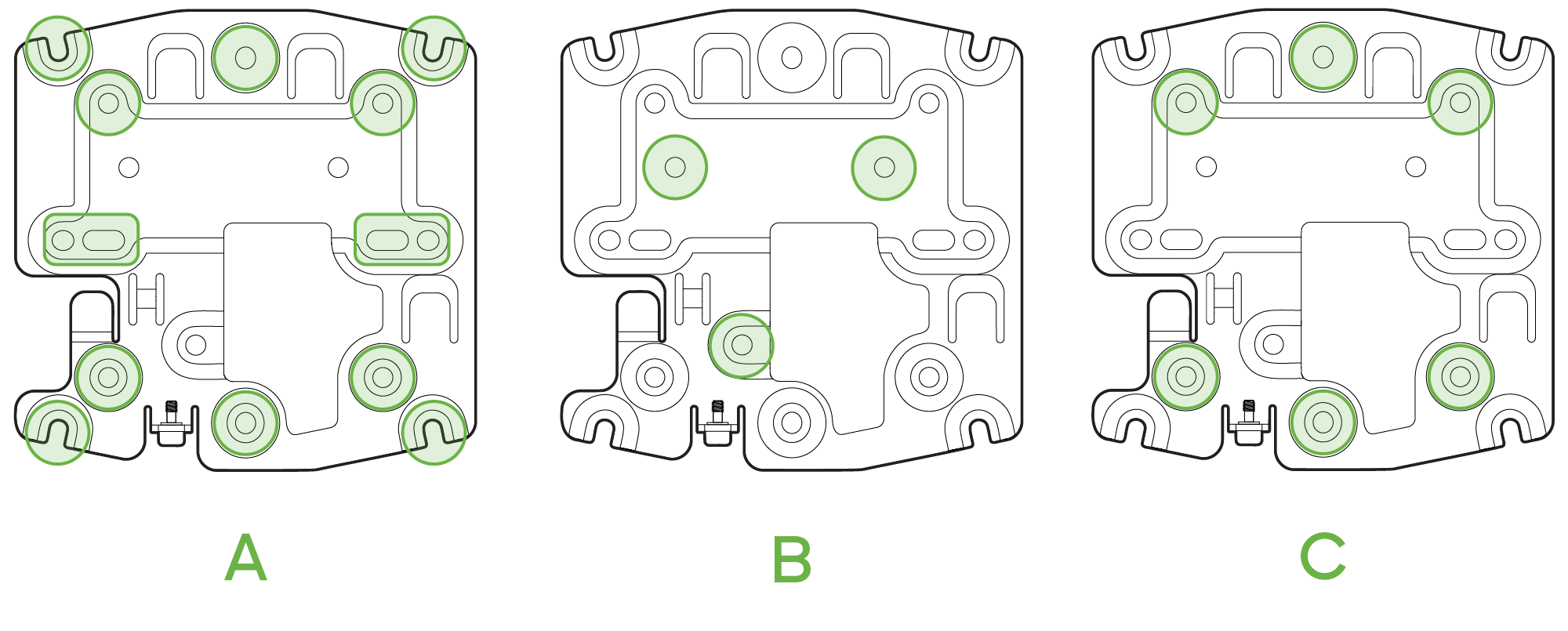
In order to mount the sensor on different locations, there are 2 supported orientations
-
Wall - The mounting plate can be directly screwed onto the wall (Option B) or on a Junction Box.
-
Ceiling - The device can be mounted on a ceiling using the included screws, or by using a T Rail mount (Not included) (Option C), or on a Junction Box (Option A).
-
-
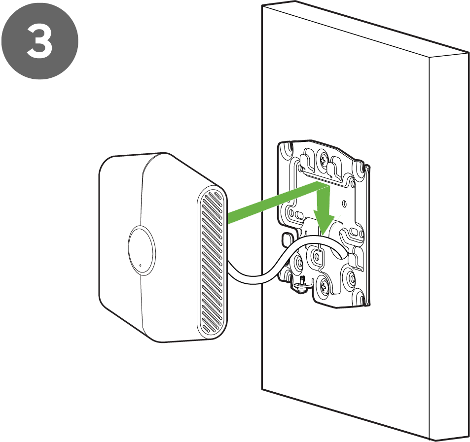
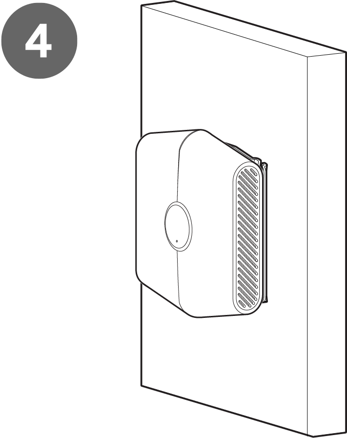
Once the mounting plate is on the desired surface, slide the MT15 sensor onto the plate.
-
Screw the Security Screw into the MT15.
Support and Additional Information
If issues are encountered with device installation or additional help is required, contact Meraki Support by logging in to dashboard.meraki.com and opening a case by visiting the Get Help section.
For additional information on Meraki hardware and for other installation guides, please refer to documentation.meraki.com.