

Multi-Network Deployment Guide
Deployment Overview
It is highly recommended to go through the following Campus Gateway documentation to get familiar with many of the Campus Gateway concept described in this document:
- For instructions of initial setup for Campus Gateway: Campus Gateway Installation Guide
- For deployment of Campus Gateway: Campus Gateway Deployment Guide
- For design considerations, architecture, and best practices for Campus Gateway: Campus Gateway Design and Best Practices
Multi-Network is a feature in Meraki dashboard that leverages the Network Groups and SSID Profiles features as well as the Cisco Campus Gateway to allow customers to easily manage configuration, monitor clients, and, most importantly, achieve seamless and fast roams across APs residing in different Meraki Networks.
Previously, Meraki Networks defined the fast roaming domain and configuration domains for the clients and devices within.
- Fast Roaming: Within a Meraki Network, the client pairwise master keys (PMK) required for client to AP communication is cached and shared only between APs within that Network. This allows the clients to fast roam between these APs without the need to reauthenticate each time. The PMKs are not shared between APs in different Networks. Thus, even if an SSID and its settings are identical, the client will do a hard roam and re-authenticate when roaming between APs in different Networks.
- Configuration: The configurations for the devices and WLANs within a Network are unique to that Network. These are not shared and synced between different Networks outside of using a configuration template. Additionally, for centralized wireless architecture with the Cisco Campus Gateway (CG), the Access Points (APs) could only tunnel to CGs that are in the same Meraki Network.
- Monitoring: The monitoring information for clients and devices are only stored and seen in the context for the current Network.
Multi-Network lifts these restrictions by leveraging the Network Groups and SSID Profiles features as well as the Cisco Campus Gateway. Now, with Multi-Network, APs placed in different Meraki Networks can tunnel to common CG clusters that are placed in a dedicated Campus Gateway Network while clients can have a fast and seamless roam across these APs regardless of the Network. Campus Gateway and APs can still be in the same network as in pre–Network Groups deployments. To allow for higher AP scale and throughput, additional CG clusters can be added to this network.
Network Groups is a new management construct within dashboard that allows network admins to logically group multiple Meraki Networks within the same Organization. This accomplishes two main goals:
- Manage configuration easily across multiple Networks via the new Configuration Profiles
- Provide Monitoring capabilities across multiple networks
Network Groups provides the management framework for configuration and monitoring of a campus wireless network when paired with the Cisco Campus Gateway (CG). However, Network Groups do not need to include networks that have Campus Gateway.
Note: Campus Gateway and APs which are in a Network Group should be part of the same geo location (RTT < 20 ms). This is the max amount of time allowed for the PMK distribution between the Campus Gateways and the APs.
Additionally, APs can tunnel traffic to different clusters for different SSIDs and use-cases. For example, the Corporate SSID can tunnel to the Corporate Cluster and Guest SSID goes to Guest Cluster.

Campus Gateway and AP Networks do not always need to be part of the same Network Group. This is the case when large-scale roaming domains (greater than 200-300 APs) are not required (for more information on roaming domains, please refer to the Roaming Domains section). In that case, AP networks would be considered Remote Sites (refer to the Remote Sites section).
Deployment Goal
- Deploy a Network Group containing Campus Gateway Networks and Access Point Networks
- Allow clients to have fast and seamless roams between APs in different Networks
- Define a Organization-wide SSID for easier configuration management between Networks
Pre-Deployment Requirements
Hardware Requirements
- One or two Campus Gateway appliances per cluster
- Campus Gateway hardware within the same CG network must be of the same hardware type to ensure consistent scale. For example, if a cluster of CW9800H1-MCG devices already exists in Campus Gateway Network 1, a cluster of CW9800L-MCG devices cannot be added because their scale is much lower.
- Cisco cloud-managed Access Points (MR and CW series) – Wi-Fi 6 or later
- Upstream switch with sufficient MAC and ARP table scale (refer to the Recommended Upstream Switches section in the product documentation)
- At least two physical uplink ports connected from each Campus Gateway to the upstream switch for link redundancy
- Redundancy Port (RP) cabling for high availability clusters:
- 1x 1G RJ45 copper port, or
- 1x 1G/10G SFP/SFP+ fiber port
- Use only ports of the same speed and type for uplink connections (either all 10GE or all 25GE) is suggested
- Appropriate SFP/SFP+ modules for fiber connections (refer to the Supported SFP Modules section in the product documentation)
Scale and Throughput
Scale
Standalone or cluster scale
| Campus Gateway | Access Points | Clients |
| CW9800H1-MCG | 12,000 | 64,000 |
| CW9800L-MCG | 1,000 | 10,000 |
Roaming domain (Campus Gateway Network) scale
| Campus Gateway | Access Points | Clients |
| CW9800H1-MCG | 12,000 | 64,000 |
| CW9800L-MCG | 1,000 | 10,000 |
Throughput
Throughput per cluster
| Deployment Mode | ||
| Campus Gateway | Standalone | Cluster of Two |
| CW9800H1-MCG | Up to 100 Gbps | Up to 200 Gbps |
| CW9800L-MCG | Up to 10 Gbps | Up to 20 Gbps |
Roaming domain (Campus Gateway Network) throughtput - Cluster of Two
The table below shows the aggregate throughput based on the number of clusters per network, assuming clusters of two.
| Number of clusters per Network | ||||
| Campus Gateway | 1 cluster | 2 clusters | 3 clusters | 4 clusters |
| CW9800H1-MCG | Up to 200 Gbps | Up to 400 Gbps | Up to 600 Gbps | Up to 800 Gbps |
| CW9800L-MCG | Up to 20 Gbps | Up to 40 Gbps | Up to 60 Gbps | Up to 80 Gbps |
Software Requirements
The first software release version that supports Network Groups is:
- Campus Gateway: MCG 32.2.X
- Access Points: MR 32.2.X.
Network Groups will not appear on the dashboard until a Campus Gateway is added to the network and upgraded to at least MCG 32.2.X.
Licensing Requirements
Campus Gateway will not require a dedicated license, but it is required for the APs to have at least Enterprise/Essentials or Advanced/Advantage tier license.
Note: Organizations are required to be using either Co-Term, Meraki subscription, or Cisco Networking subscription licensing.
Network Requirements
- IP Addressing: IPv4 address (either DHCP or static IP assignment) for the Campus Gateway Management Interface; static IPv4 assignment for the AP Tunnel Interface
- IPv6 for Campus Gateway interfaces is not currently supported
- VLANs:
- Management VLAN, AP Tunnel VLAN (if using dual L3 interface deployment), and client VLANs (any valid ID in range of 1-4094, excluding 1002-1005)
- Firewall Rules:
- Allow outgoing connections on ports and IP addresses listed under Help > Firewall info in the Meraki dashboard
- Refer to Upstream Firewall Rules for Cloud Connectivity for the full list
- If a firewall exists between Campus Gateway and APs, open:
- UDP port 16674 for QUIC
- UDP port 16675 for VXLAN
- DHCP: Active on at least one VLAN on the uplink switch, with a default gateway and DNS server, so the Campus Gateway can reach the Meraki dashboard
- DNS: DNS servers must be provided via DHCP or static configuration so the Campus Gateway can reach the Meraki dashboard
- Trunk Configuration: 802.1Q trunk on the upstream switch ports connected to Campus Gateway, with at least one active VLAN
- RP Link Requirements (for HA clusters):
- Latency < 80 ms
- Bandwidth > 60 Mbps
- MTU >= 1500 bytes
- Inter-DC Requirements (if deploying across data centers): Layer 2 connectivity is required so that Management VLANs, client VLANs, and RP VLAN can be shared (refer to the Recommended cluster deployment topologies section in the Campus Gateway Design and Best Practice Guide)
Skillset Requirements
- Understanding of when to use a centralized vs distributed wireless design
- Understanding of how to install and deploy a Cisco Campus Gateway and Cloud-managed access points
Network Design
In a Network Group, a Network with at least one Campus Gateway cluster is a Campus Gateway Network. A seamless roaming domain is defined as the set of APs in one or more AP Networks tunneling to CG cluster(s) in a single Meraki Network (also called a CG Network).
Tunneling to a CG Network allows for a seamless roam since the client will maintain the same IP address and policy across Layer 3 boundaries.

When APs are configured to tunnel to a CG Network, each AP forms QUIC tunnels to all the clusters within that network.
In a CG Network, clients' PMKs are shared between all cluster members for fast roaming across different AP Networks.
Note: All Campus Gateway clusters that APs tunnel to must reside within the same Campus Gateway Network. Splitting SSID tunneling across different Campus Gateway Networks is not supported.
A Network Group can support multiple roaming domains by having multiple CG Networks. Different sets of APs tunnel to their respective CG Networks. Roaming across CG Networks is a slow roam with full client reauthentication—no client handoff occurs for inter-CG Network roaming.
Roaming Domains
A Roaming Domain is defined as the set of APs in one or more AP Networks tunneling to CG Cluster(s) in a single Network (a.k.a. Campus Gateway Network). Each AP tunneling to a CG Network containing multiple clusters, forms QUIC tunnels with all the CG clusters in the Network. Tunneling to a CG Network allows for the same client IP and policy to be maintained across L3 boundaries. In the CG Network the clients’ PMKs are shared between all the cluster members for fast roaming across different AP Networks. Tunneling different SSIDs to different CG networks is not supported. A Network Group can support multiple roaming domains, however roaming across these domains will result in a slow roam with full client re-authentication.
Layer 2 vs Layer 3 roaming
For Campus Gateway clusters within the same roaming domain (Campus Gateway Network), the type of roaming (Layer 2 vs Layer 3) depends on the availability of the client VLANs in each cluster.
| Type of Roam | VLAN Availability across Clusters |
| Layer 2 | Same set of client VLANs for an SSID |
| Layer 3 | Different set of client VLANs for an SSID |
Layer 2 roaming

In an inter-cluster Layer 2 roam, client traffic is terminated by the primary Campus Gateway for the AP that the client is connected to.
For example:
-
Cluster 1 (C1) and Cluster 2 (C2) are in the CG Network.
-
AP1 in Network 1 has Cluster 1 (C1) as its primary.
-
AP2 in Network 2 has Cluster 2 (C2) as its primary.
-
Both clusters, C1 and C2, are configured with the same client VLANs (VLAN 10 in this example) for the SSID.
When a wireless client connects to AP1, the client's traffic is terminated by C1 and sent out on VLAN 10. Once the client roams from AP1 to AP2, the traffic goes out from C2 on VLAN 10. Because C2 has the same VLAN 10, a client handoff occurs between CG Clusters.
Layer 3 roaming

In an inter-cluster Layer 3 roam, client traffic is anchored to the primary Campus Gateway for the AP that the client initially connected to.
For example:
-
AP1 has Cluster 1 (C1) as its primary.
-
AP2 has Cluster 2 (C2) as its primary.
-
C1 is configured with VLAN 10 for the SSID.
-
C2 is configured with VLAN 20.
When a wireless client connects to AP1, the client's traffic is terminated by C1 and sent out on VLAN 10. Because C2 does not have VLAN 10 configured, when the client roams from AP1 to AP2, AP2 anchors the client traffic back to C1. This allows the client traffic to continue on VLAN 10 without requiring a new IP address.
Suggested campus topologies
Shared corporate and guest clusters

In this topology, all SSIDs—Corporate and Guest—are available on all AP networks and on each cluster in the Campus Gateway Network. The APs tunnel to all clusters in the Campus Gateway Network.
Because the Guest SSID traffic is terminated on the same CG clusters as corporate traffic, segmentation is supported only via VLAN segmentation. The Guest SSID must map to a guest VLAN that is terminated to a VRF interface on the firewall. If the firewall is not Layer 2 adjacent to the CG cluster, transport the Guest VLAN using a wired network mechanism such as VRF light or BGP EVPN.
Additional clusters can be added to the CG Network for horizontal scaling. The maximum is four total clusters per Network.
Dedicated corporate and guest clusters

In this topology, all SSIDs—Corporate and Guest—are available on all AP networks. The APs form tunnels to all clusters in the Campus Gateway Network. The Corporate SSID is terminated onto the Corporate cluster(s) and the Guest SSID is terminated onto the Guest cluster(s). Corporate and Guest traffic can be separated via a firewall. For example, the Guest cluster could be placed in the DMZ. If the APs can reach both clusters, the tunnels will come up.
Additional clusters can be added for either the Corporate or Guest traffic. Any combination of Corporate and Guest clusters is supported as long as the total number of clusters within the CG Network does not exceed four.
Supported combinations:
-
3 Corporate clusters and 1 Guest cluster
-
2 Corporate clusters and 2 Guest clusters
-
1 Corporate cluster and 3 Guest clusters
Remote sites deployments

Campus Gateway and APs do not always need to be part of the same Network Group. This applies when some traffic needs to be centralized, such as accessing corporate resources in the data center, but large-scale roaming (fewer than 200–300 APs) or roaming across Layer 3 boundaries is not required.
If an AP Network is not part of a Network Group, but the APs in that AP Network tunnel traffic to a CG cluster in the Network Group, those AP Networks are considered remote sites. A Campus Gateway Network can support up to 500 different remote site AP networks.
In a remote site, the control plane, including client PMK distribution, is distributed among the APs and not centralized at the CG cluster. Because of this, the latency between CG and AP can exceed 20 ms RTT, allowing traffic to traverse WAN networks. The below table gives the max latency for AP to CG communication.
| Deployment Type | Max RTT Latency |
|---|---|
| Data Only | 300 ms |
| Data + Voice | 100 ms |
The traffic from remote sites to the CG Networks is secured when going over WAN networks:
-
Control plane: QUIC tunnels are always encrypted.
-
Data plane: VXLAN tunnel management traffic is always encrypted. Client data traffic can be encrypted if desired. Refer to the VXLAN Tunnel Encryption guide.
Disaster recovery
Disaster Recovery (DR) allows a CG cluster to act as a backup cluster for APs tunneling to their primary CG cluster. This is similar to the N+1 High Availability solution for the WLC.
If both Campus Gateways in the APs' primary CG cluster fail (that is, the cluster fails), the APs connect to the DR CG cluster. Upon failover to the DR cluster, APs are load balanced between the tertiary CG and quaternary CG—in the same way they were load balanced between primary and secondary in the primary cluster.
Failover between the primary cluster and DR cluster is stateless. The client state is not plumbed to the data plane of the DR cluster. Clients remain connected to the AP because the client state machine is maintained on the AP.
Because failover is stateless, AP failover to the DR cluster takes 9–11 seconds. Once the remaining CG in the primary cluster fails, the only detection mechanisms the APs can rely on are the VXLAN and QUIC tunnel keepalives.
-
The VXLAN tunnel failure is detected first. The BFD protocol detects the tunnel as down in 9 seconds.
-
The BFD echo is sent every 5 seconds, with an echo sent every 1 second if one echo is missed.
-
Once the VXLAN tunnel is detected as down, the QUIC tunnel is also taken down. APs then fail over to the DR cluster in 1–2 seconds.
If any CG from the primary cluster comes back online, an automatic fallback to the primary cluster occurs within 3 minutes of the first CG returning.
The DR cluster is defined and configured for each cluster, not at the SSID level. All SSIDs tunneling to a Campus Gateway cluster use the same DR cluster.
A single DR cluster can back up multiple primary clusters. However, only one cluster failure is supported at any time per DR cluster. A Cluster that is actively tunneling SSID traffic can backup another cluster that is also actively tunneling AP traffic.
Design considerations for the DR cluster:
-
Both the primary and DR cluster must belong to the same CG network.
-
Failover can only happen to a cluster that supports all VLANs of the failing cluster.
-
The DR cluster must have the capacity to take on the AP and client load from the most loaded primary cluster.
Deployment preparation
Before deploying Network Groups, complete the following prerequisite:
-
Firmware management: Upgrade the Campus Gateway and APs to MCG/MR 32.2.3
Deployment procedure steps
Creating the Network Group
-
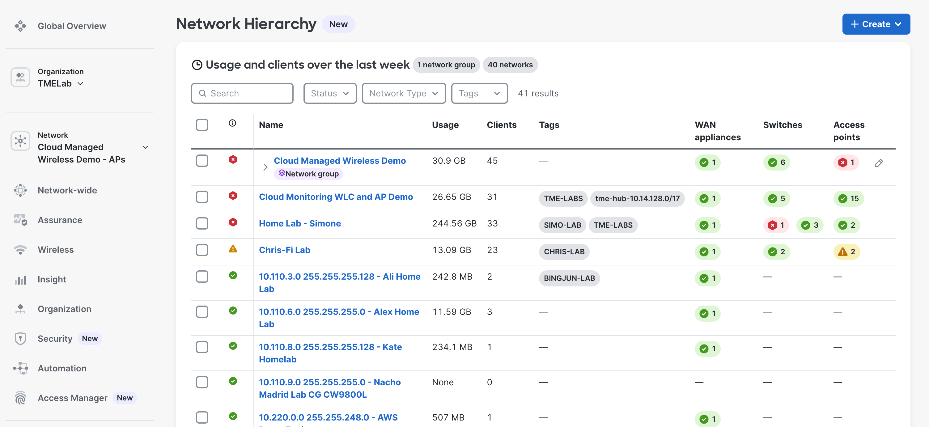
Navigate to Organization > Configure > Network Hierarchy.
-
In the Network Hierarchy page, choose Create and select Network group.

-
In the dialogue box, enter a name for the Network Group and choose Create.

Adding a Network to a Network Group
-
Navigate to Organization > Configure > Network Hierarchy.
-
Select the checkbox for each Network to add to the Network Group.

-
Choose Group network.

-
In the Group network dialogue box, the selected networks can be added to an existing Network Group or a new Network Group.
SSID tunnel configurations will be preserved when moving a combined AP and Campus Gateway network into a network group. If moving AP only networks that have tunnel configurations for Campus Gateways that are not part of the network group, the SSID IP and VLAN section will be reset to NAT and will need to be reconfigured after the move.
-

a. If adding to a new Network Group, enter the name for the Network Group.

-
Choose Save to add the networks to the selected Network Group.
Removing a Network from the Network Group
-
Navigate to Organization > Configure > Network Hierarchy.
-
Select the checkbox for the Network Group from which networks will be removed.

-
Choose Manage group > Remove networks.

-
In the dialogue box, select the networks to remove and choose Next.

-
An alert warns that the following SSIDs will be reset and connectivity will be disrupted. Select the checkbox to acknowledge the disruptive action and choose Remove and reset SSIDs.

SSID Profiles
Note: In order to roam across APs in different Networks with Campus Gateway, SSIDs must be provisioned via an SSID Profile. SImply, matching the SSID settings for each Network is not sufficient as the necessary configurations needed for PMKs to be distributed to APs across different Networks is only generated when SSID Profiles are applied.
For clients to have seamless roaming across APs in different Meraki Networks, some elements of an SSID configuration must be identical across networks. Specifically, the 802.11 and authentication elements of the SSID configuration must match to allow fast, seamless roaming. Previously, SSIDs could only be configured at the Network level, which required a network administrator to manually duplicate SSID configurations across AP Networks. This process was both tedious and error-prone.
Configuration Profiles allow users to define settings at an Organization level and apply them to various networks. For wireless, the Configuration Profile is called the SSID Profile. SSID configurations can be defined at the Organization level, allowing administrators to define the base settings of an SSID and apply it to all required AP Networks. This provides a single source of truth for roaming configurations across networks. The available configurations match those on the Access Control page for Network SSIDs.
To avoid configuration drift between networks, most settings in the SSID Profile cannot be overridden. For flexibility, some settings are defined within each Network:
-
Client VLAN assignment
-
Campus Gateway Cluster
-
RADIUS server (if network-specific configuration is enabled in the SSID Profile)
Configure an SSID Profile
-
Navigate to Organization > Configure > Configuration profiles.
-
In the SSID profiles tab, choose Create SSID profile to open the SSID profile wizard.
.png?revision=1)
-
Basic info tab: Enter the profile name and SSID name.
Note: The profile name and SSID name can differ from each other.
.png?revision=1)
-
Security tab: Configure the required security settings for the SSID. Refer to the Security section of the Access Control article for more information on configuring SSID security.
.png?revision=1)
-
RADIUS servers can be configured in two ways for deployment flexibility:
-
Within the SSID Profile: Select an Organization-wide defined RADIUS server or add a new RADIUS server manually. Refer to the RADIUS server section in the Organization settings article.
.png?revision=1)
-
Within each individual network: Set the toggle to enable Configure per Network SSID.
With this option, every time the SSID Profile is applied to a Network, the RADIUS server will need to be configured.
.png?revision=1)
-
-
Splash tab (if applicable): Configure the splash page settings for the SSID. Refer to the Advanced splash settings section of the Access Control article.
-
Client IP and VLAN tab: Configure settings for how the client receives a VLAN and IP address. While locally bridged SSIDs are supported within the SSID Profile, this guide configures the SSID Profile with a centralized SSID to Campus Gateway by choosing Tunnel mode with Campus Gateway (CG).
Note: For flexibility, the Campus Gateway Network and Cluster are selected within each individual Network.
For a Campus Gateway-tunneled SSID that requires mDNS, configure the mDNS gateway with the required mDNS services. Refer to the mDNS Gateway section of the Campus Gateway deployment guide.
.png?revision=1)
-
Choose Save.
Applying an SSID profile to a Network
-
In the Configuration Profile > SSID Profile tab, find the SSID profile to apply.
-
Under the Applied to tab, choose 0 networks to open the SSID profile assignment window.
Note: The number displayed changes based on how many networks the profile is assigned to.
.png?revision=1)
-
Find the network to apply the SSID profile to and choose the SSID that the profile will map to. This can be an active or disabled SSID.
Note: Search for specific networks by name, or filter the network list by Network Group.

After choosing the network and SSID, choose Continue to network SSID details. A new tab opens to the respective network SSID's Access Control page.

-
In the Access Control page, configure the network-specific SSID settings. These include Campus Gateway Network, CG Cluster, client VLAN, RADIUS server (if not in the SSID Profile), and so on. Choose Save when done.
Warning: If applying to an active SSID, the SSID profile settings overwrite the existing SSID configurations. Record the previous configurations before applying if needed.

Applying the SSID Profile to another Network
-
In the Configuration Profile > SSID Profile tab, find the SSID profile to apply.
-
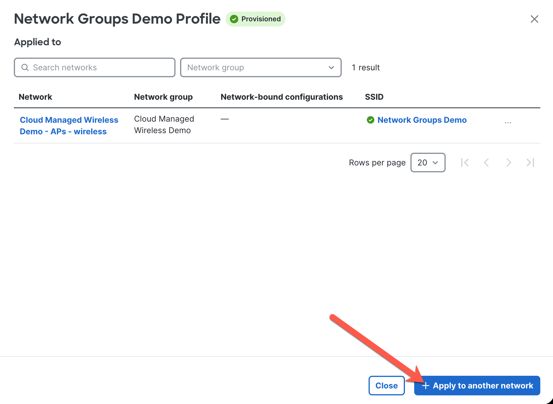
Under the Applied to tab, choose X networks to open the SSID profile assignment window.
Note: X represents the number of networks, which changes based on how many networks the profile is assigned to.
-
Choose + Apply to another network.
-
Follow steps 3–4 in the "Applying an SSID profile to a Network" section.
Warning: If applying to an active SSID, the SSID profile settings overwrite the existing SSID configurations. Record the previous configurations before applying if needed.
Applying the SSID Profile via the Network SSID Access Control page
-
Navigate to the required network SSID's Access Control page.
-
Select the Apply SSID profile checkbox and choose the required SSID profile.

-
Configure the network-specific SSID settings. These include Campus Gateway Network, CG Cluster, client VLAN, RADIUS server (if not in the SSID Profile), and so on. Choose Save when done.
Warning: If applying to an active SSID, the SSID profile settings overwrite the existing SSID configurations. Record the previous configurations before applying if needed.
Disaster Recovery Cluster
- Navigate to Wireless > Campus Gateway (MCG) > Campus Gateways.
- Go to the Campus Gateway cluster that needs to be configured and click Edit.

- In the Disaster recover cluster option, select which cluster should be the DR cluster for all the SSIDs tunneling to the cluster. Click Save.
Note: Disaster Recovery clusters are on a per-cluster basis.

Remote site configuration
- Add the Campus Gateway Network is place within a Network Group. Please refer to the Adding a Network to a Network Group section.
- Ensure the AP Networks that will be configured as remote sites are not part of a Network Group where the CG is located.
- Configure the Campus Gateway tunneled SSID for each AP Network. This can be done either using an SSID Profile (refer to the Applying an SSID profile to a Network section) or within the Access Control page of the network's SSID (refer to the Applying the SSID Profile via the Network SSID Access Control page section).
Firmware upgrades
Both the Minimize upgrade time and Minimize client downtime upgrade mechanisms are available for Network Groups deployments. This is the same as for pre–Network Groups deployments for Campus Gateway and APs.
Firmware version constraints
Campus Gateway and AP firmware versions use the format X.Y.Z (for example, MCG 32.2.3 and MR 32.2.3):
-
X is the major firmware version—32
-
Y is the minor firmware version—2
-
Z is the patch firmware version—3
When part of a Network Group, the following firmware version constraints apply to both the Campus Gateway and access points:
-
All Campus Gateways and APs must run MCG 32.2 / MR 32.2 or newer.
-
Campus Gateway MCG 32.2.Z is incompatible with MR 31.2.Z or 32.1.Z.

-
-
Campus Gateway firmware can be at most one major version ahead of the access point firmware (for example, MCG 34.1.1 and MR 33.1.1).

-
Access point firmware can only be ahead of Campus Gateway firmware by patch version (for example, MCG 32.2.3 and MR 32.2.4).

Minimize upgrade time
Note: This is the only option when selecting every network in the Network Group to upgrade.
When selecting the Minimize upgrade time option for firmware upgrades, the dashboard performs the following steps:
-
Upgrades each CG in each cluster of the Campus Gateway Networks in the Network Group together.
-
Then upgrades each AP in each AP Network in the Network Group together.
For example: A network contains Clusters 1–4 running MCG 32.2, and networks containing the APs are running MR 32.2. The network admin schedules all networks to upgrade to MCG 33.1 and MR 33.1 using Minimize upgrade time.
-
First, upgrades Clusters 1–4 from 32.2 to 33.1. Status: Cluster 1 (33.1) + Cluster 2 (33.1) + Cluster 3 (33.1) + Cluster 4 (33.1) + MR (32.2).
-
Then upgrades all APs from 32.2 to 33.1. Final status: Cluster 1 (33.1) + Cluster 2 (33.1) + Cluster 3 (33.1) + Cluster 4 (33.1) + MR (33.1).
Minimize client downtime
Note: This option is available only when upgrading CG networks and AP networks independently. Select either a CG network or an AP network (or a specific set of AP networks) to upgrade. Upgrading both types of networks simultaneously in the same action is not allowed.
Note: If there is a combined CG and AP network, the Minimize client downtime option is available as long as the firmware upgrade follows the version constraints in the Firmware version constraints section. Otherwise, only Minimize upgrade time is available.
When selecting Minimize client downtime for the Campus Gateway Network, the dashboard upgrades one CG from each cluster at a time.
For example, a network contains Clusters 1–4. Each cluster has a pair of Campus Gateways in Active-Active mode (for example, Cluster 1 has CG 1A and 1B). Each cluster runs MCG 32.2 and networks containing the APs run MR 32.2. The network admin schedules only the Campus Gateway Network to upgrade to MCG 33.1 using Minimize client downtime.
-
Upgrades CG 1A/2A/3A/4A from MCG 32.2 to 33.1 first. Status: CG 1A/2A/3A/4A (33.1) + CG 1B/2B/3B/4B (32.2).
-
Then upgrades CG 1B/2B/3B/4B from 32.2 to 33.1. Final status: CG 1A/2A/3A/4A (33.1) + CG 1B/2B/3B/4B (33.1).
When selecting AP Networks to upgrade with Minimize client downtime, the upgrade process follows the process in the Access Point Upgrade Strategy documentation. The dashboard upgrades APs one group at a time on a rolling basis to maintain adequate RF coverage for wireless clients during the upgrade process.
Post-Deployment Verification
Connectivity tests
-
Connect wireless clients to APs in a different network from the CG network.
-
Connect using various security types (for example, passphrase, 802.1X, OWE, or captive portal).
Feature validation
Cross-network roaming
-
Place two different APs in two different Meraki Networks and configure an SSID to tunnel to a CG in another network.
-
Connect a client to the tunneled SSID.
-
Move the client between the APs to trigger a roam.
-
Verify that 802.11r is occurring.
SSID Profile application
-
Verify the settings configured in the SSID Profile have been correctly applied to the network SSID.