
Meraki Wireless for Enterprise Best Practices - Architecture
Introduction
Cisco® Meraki is the best-in-class cloud-managed network offering from Cisco. It combines RF excellence gained in 25 years of leading the wireless industry with Cisco IOS® XE and AireOS software and combines it with the simplicity and scalability of the cloud.
Compared to the traditional need for a wireless LAN controller (WLC) to manage access points, such as the AireOS WLC or Cisco Catalyst 9800, Meraki Access Points (MR) are directly managed from the cloud via Meraki Dashboard. This allows customers to manage their wireless networks anywhere, across multiple sites, without the need to VPN into the network, as they now have a single cloud application to manage their networks.
This document covers the best practices recommended for configuring and deploying Meraki Wireless networks for large-scale enterprises. The objective here is to provide common settings that can apply to most wireless network implementations. However, not all networks are the same, so some recommendations may not apply to your network. Always verify them before performing changes on a live network.
Large Campus Design for Meraki Wireless
Distributed Data Plane Approach
In a Large Campus deployment, Meraki Wireless is recommended to be deployed with at most 800 APs and 10K clients per Meraki Network today with seamless and fast roaming. Meraki Wireless deployments leverage a distributed data plane approach, meaning that all the MR access points locally switch all the wireless traffic to the rest of the network. This is like a FlexConnect deployment using a Cisco AireOS or Catalyst 9800 WLCs.
One of the main benefits of the distributed data plane approach is that it addresses the throughput demands of newer Wi-Fi standards, like Wi-Fi 6E and beyond, since each AP will switch all its wireless traffic locally to the rest of the network. Unlike centrally switched WLC-based deployments where throughput is limited by the WLC, the total throughput of a distributed wireless network scales based on the number of access points and is only limited by the underlying switching architecture.
Additionally, since Meraki leverages the distributed data plane and a cloud-based device manager, it reduces the amount of equipment that needs to be deployed since, for most cases, a WLC is not required as the Meraki Dashboard manages and monitors all devices in the network. Only MR Access Points are needed to deploy.
However, using a distributed data plane approach requires more planning on the roaming domains and switching architecture.
Switching Architecture
When designing the underlying switching architecture, the ports on the access switches that are connected to the APs follow these recommendations:
- The ports should be configured as trunk ports to allow the APs to pass multiple VLANs when they switch the wireless traffic to the wired network.
- Ensure the VLANs for management traffic for the APs and each broadcasted SSID are allowed on the port.
- For zero-touch provisioning of the MR, set the native VLAN on the trunk port to be the management VLAN for the APs.
- Configure the ports with Spanning Tree Portfast Trunk, BPDU guard, and Root guard.
For more information, please see the article on VLAN Tagging on MR Access Points: https://documentation.meraki.com/MR/Client_Addressing_and_Bridging/VLAN_Tagging_on_MR_Access_Points
If wired clients are connected to the same switch, the VLANs associated with the wired clients should be confined to that specific access switch (see the example below). VLANs associated with the wireless clients should span across all the access switches that are within the roaming domain. This will be discussed in the next section.
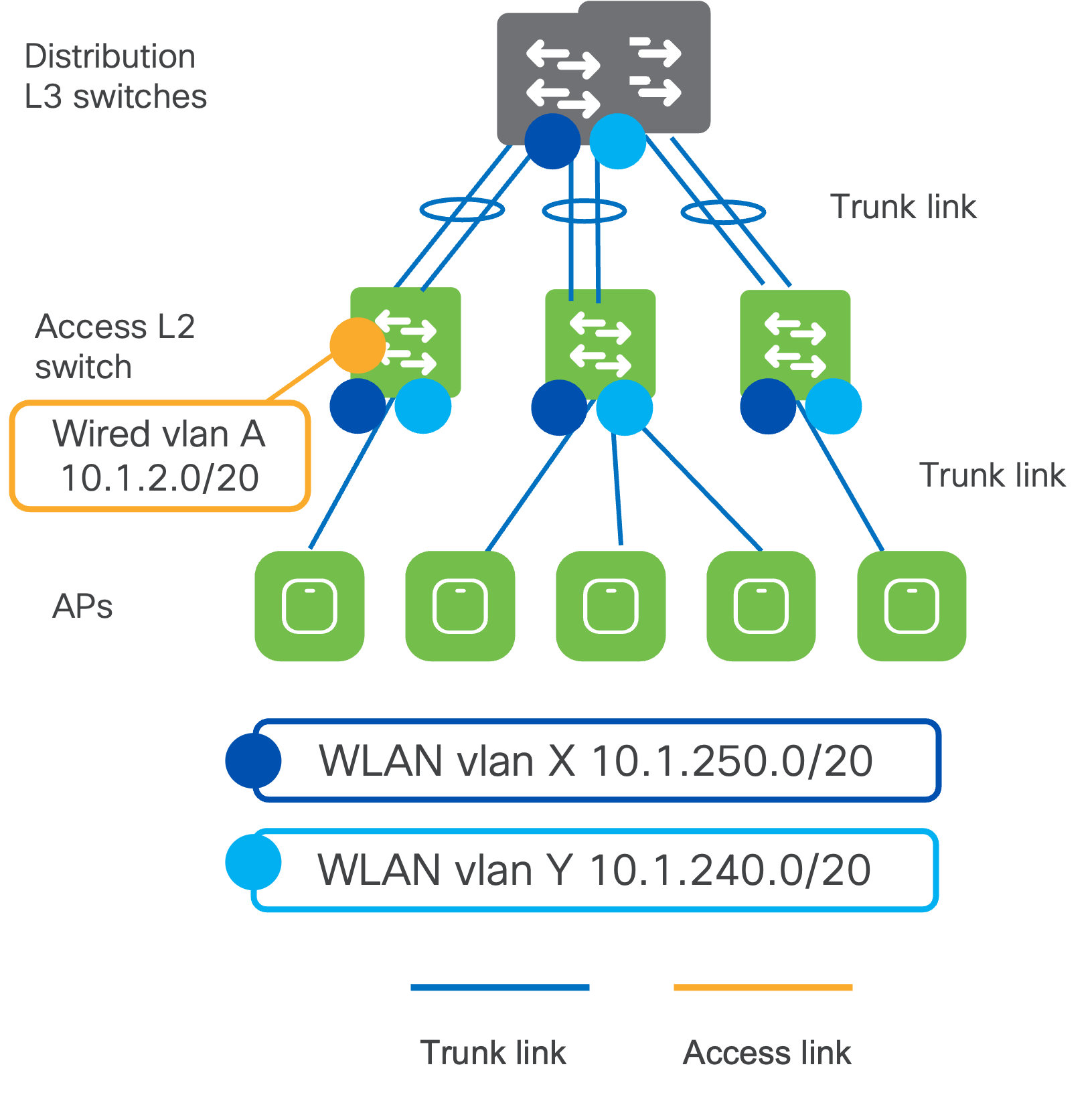
Moving up to the distribution layer switches, it is recommended to configure the distribution switches in either:
- StackWise Virtual / Virtual Stacking
- Provides redundancy at the distribution layer with no deliberate layer 2 (L2) loops.
- Uplinks from the access switches to the distribution switch must be configured as trunk ports and in EtherChannel.
- Prune the allowed VLANs on the trunk ports to only the required VLAN.
- HSRP / VRRP
- Provides first-hop redundancy.
- STP Root and HSRP primary should be configured on the same switch.
- Uplinks will be configured as trunks and EtherChannel.
- BPDU and Root Guard on downlinks and Loop Guard on uplinks
- Only the required VLANs should be allowed on trunks to the distribution layer.
The VLANs the wireless clients are placed in when connecting to the WLANs must be allowed on the trunks between the distribution and all the access switches that are part of the roaming domain.
Dual PoE for MR57 (PoE Redundancy and LACP)
MR57 has two Ethernet ports and can support 802.3af/802.3at/802.3bt/UPoE.
There are three PoE operation modes:
- Single PoE: Only one Ethernet port receives PoE.
- Dual PoE (power sharing mode): Both Ethernet ports receive PoE. The power is split on both ports, not necessarily even.
- Dual PoE (dual-uplink mode): Both Ethernet ports receive PoE. If PoE on one of the Ethernet ports fails, MR57 will seamlessly switch to the remaining Ethernet port without adversely affecting wireless clients' connectivity.
In power-sharing mode, the power draw is not split equally among the two PoEs. MR57 tends to draw more power from the PoE with higher voltage. For example, if MR57 is connected to two 802.3af PSE ports and draws 23W in total, MR57 could draw more than 802.3af power from one PoE port (18W) while little from the other (5W). Some switch ports might shut down the port if the PD draws more power than the switch support, and MR57 will reboot. To solve this problem, MR57 needs to set the maximum power draw from the PSE depending on the classified PD type or LLDP/CDP negotiation results.
In the High-Availability mode, MR57 will not reboot or drop any wireless clients if one of the ports loses power.
For both cases, the switch will allocate the maximum power capable to both switch ports connected to the MR57. When planning the power budget, this behavior needs to be considered as the power allocated per AP will now be doubled.
For more information, please see here: https://documentation.meraki.com/MR/MR_Overview_and_Specifications/MR57_Dual_Uplink_High_Availability
Roaming Domains
Meraki is committed to providing an inclusive experience for our customers. The following section contains language that does not adhere to our standards for inclusivity. We are working with our partners to replace it.
A roaming domain is an RF continuity domain with the same SSID where client devices can stay connected no matter where they move within the domain. These can be multiple physical or virtual domains where users would logically move and require fast and seamless roaming to maintain connectivity for their applications.
What does fast and seamless roaming mean?
- Seamless: You have a seamless roam when the client keeps its IP address and policy as it roams across different APs. A seamless roam requires keeping stateful client information of both the policy and IP address, no matter which AP the client connects to within a roaming domain. Meraki Dashboard ensures this information is kept consistent among all APs within the network.
- Fast: You have a fast roam when a client does not have to re-authenticate every time It roams to a new AP. A fast and secure roam requires keeping the Pairwise Master Key (PMK), derived during the initial authentication, consistent and shared with the roaming domain. This guarantees small delays in roaming, usually less than 50ms. To achieve this, key caching protocols, like 802.11r or OKC, need to be enabled and supported by clients. To further optimize this, networks can take advantage of 802.11k/v.
Roaming domains include groups of floors, a single building, multiple buildings, etc. Whichever physical or virtual groupings are chosen for the roaming domain will affect how the APs are added to Meraki Dashboard. Within Meraki Dashboard, there are two main management design constructs:
- Organization: A collection of networks that are part of a single organizational entity
- Recommended number of nodes: 25,000
- Network: Set of Meraki devices, their configurations, statistics, and info. This is usually mapped to a geographical location (ex. Sites, groups of buildings, buildings, floors, etc.)
- Recommended number of nodes: 800
Note: A node is any Meraki device (MR, MS, MX, MV, MT, etc.)
A Meraki Network is the fast-roaming domain, as the client PMK information is shared between MRs that are part of the same network. Also, the APs must be in the same management VLAN and be able to communicate with each other using source port 23541 and destination port 35213. This will allow the APs to share the PMK for the clients amongst each other. Thus, client devices roam between APs in the same Meraki Network, they will do a fast roam between the APs. However, when roaming between APs in different Meraki Networks, the IP address, policy, and PMK for each client is not shared, resulting in a hard roam where the client devices must fully reauthenticate.
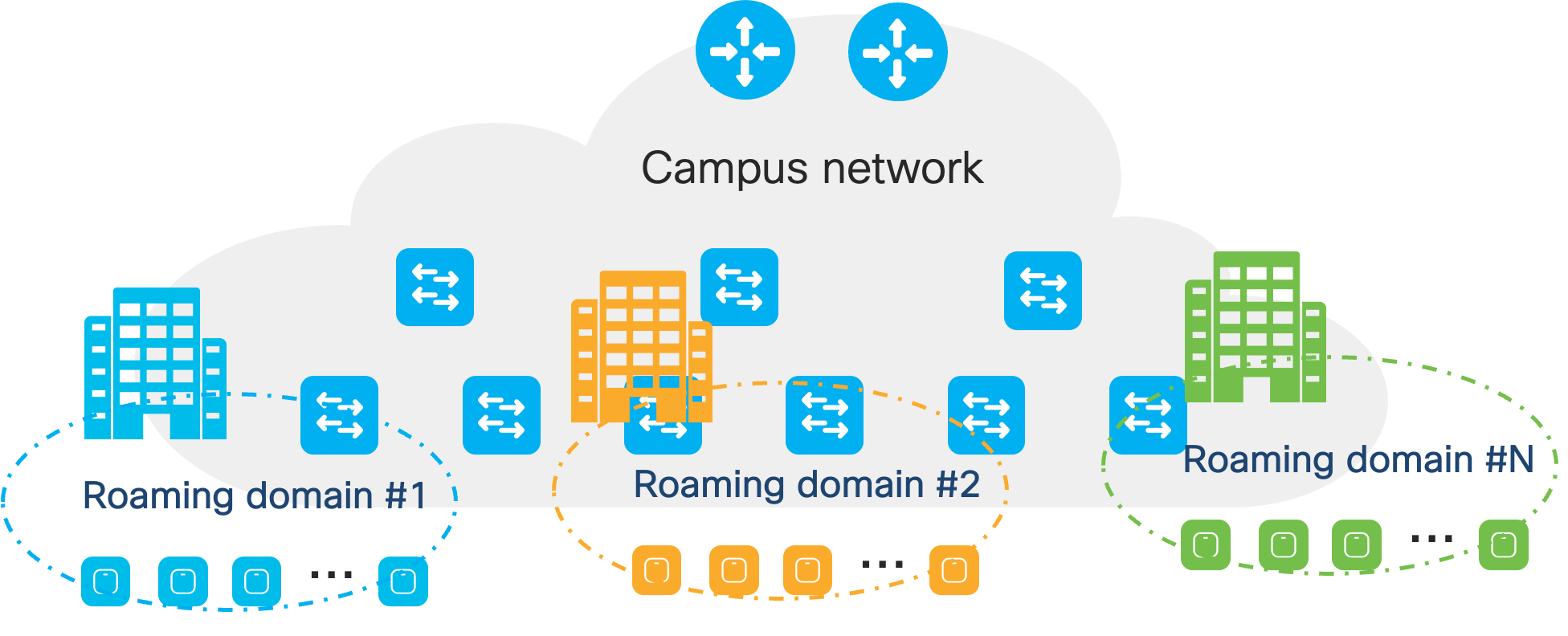
Because of this, it is essential to design the roaming domains to divide the campus's physical locations with clear RF boundaries, ensuring that clients will roam to APs within the same roaming domains. Examples of finding these divisions can be:
- Geographical Areas: Look for sections of a campus that can be logically carved out. For example, the North, South, East, and West parts of a campus are named as such for a reason.
- Outdoor Wireless: Group outdoor wireless areas within the buildings they’re attached to.
- Stadiums/Sports Venues: These areas have large amounts of clients, so it would be best to make them their own individual roaming domain and a dedicated Network for them.
It is recommended to segment the campus by building as the smallest roaming domain. This is due to RF leakage between floors, leading to client devices possibly connecting to APs on different floors. Otherwise, clients might have hard roams within the same building.
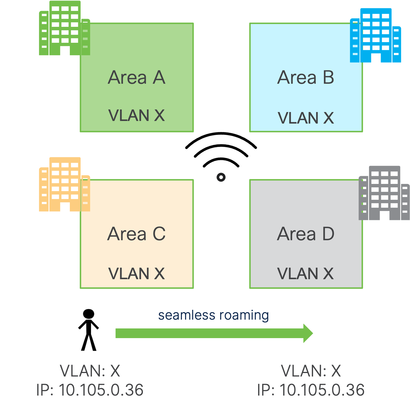
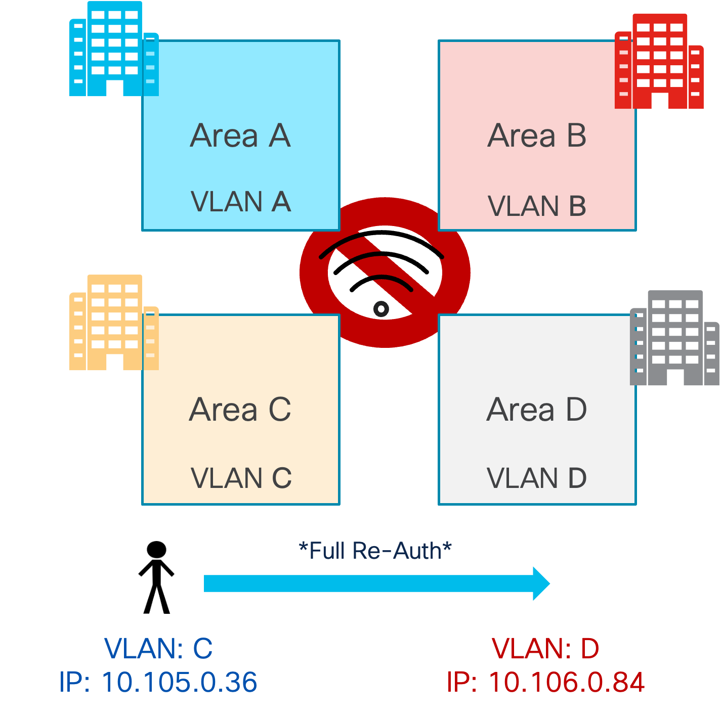
Additionally, within a Meraki Network, it is essential to understand and decide whether there will be Layer 2 (L2) or Layer 3 (L3) roaming for clients when sizing the roaming domain as this will directly be impacted by the underlying switching architecture.
- Layer 2 Roaming: This is when a client roams to another AP where the WLAN is associated with the same VLAN, maintaining its session. This is due to the SSID being the same and on the same VLAN, leading to a seamless roam (same IP address) as well as a fast roam. If clients roam to an AP where the same WLAN is associated with a different VLAN, the session breaks, and the client must eventually re-DHCP, which may take a few seconds.
- Layer 3 Roaming: If clients roam to an AP where the same WLAN is associated with a different VLAN, but there is a mechanism in place (tunneling, re-anchoring to original AP) that allows the client to keep its IP address and hence the roaming will be seamless.
|
L2 Roaming (same VLAN) |
L2 Roaming (different VLAN) |
Distributed L3 Roaming (different VLAN) ** |
|
|
Same SSID |
Client re-auth Seamless (same IP) |
Client re-auth Session breaks |
Client re-auth Seamless (same IP) |
|
802.11r (or OKC) |
Fast roaming Seamless (same IP) |
Fast roaming Session breaks |
Fast roaming Seamless (same IP) |
Distributed L3 Roaming (DL3R) is Meraki’s solution to provide seamless L3 roaming. As of today, this solution doesn’t support fast roaming at scale; hence, it is not recommended for a large enterprise campus. For this reason, it’s recommended to go with an L2 roaming solution, and it becomes essential to design the network in such a way that when seamless and fast roaming is required, the same VLAN is associated with all the MRs in the Meraki Network. If large-scale Layer 3 roaming is required, please reach out to the Cisco Wireless Business Unit.
How bad is it if there is a VLAN change and the session breaks because the client's IP address is no longer valid? It depends on the client operating system (OS):
- Even with a full re-auth on roaming (no fast roaming enabled or crossing a Meraki Network boundary), some client OSes may consider the same SSID equal to the same network and subnet, and hence, they might not check if DHCP is still valid.
- Windows OS does a DHCP inform and GW detection upon roaming, but no OS will go through the whole DHCP discovery process.
- Other client OSes will not do anything, and DHCP will time out (30-second session break)
- If roaming fails and the client receives a de-auth, then the client will do a full DHCP discovery after a new reauthentication (still 4-5 seconds)
In addition to client behavior, it is important to consider the impact on the applications and services on the network if the session breaks. Will the application recover seamlessly? Some applications like VPN will not work and need to re-establish the connection. Additionally, services like DHCP and AAA will be under extreme pressure in the case of a mass roam where client sessions must be re-established. To get around these issues, a seamless and fast roam is essential, and the same VLAN for the clients is required, which will require an L2 Roam.
However, having an L2 roam with the same VLAN for the WLAN requires the VLAN to be spanned across all the access switches within the roaming domain, possibly spanning multiple wiring closets or even multiple buildings. Depending on the number of devices in the roaming domain, there may be a requirement for a large subnet for the VLAN, which leads to a large broadcast domain.
 |
 |
The size of this VLAN will be affected by the types of Layer 2 and Layer 3 switches deployed at the site. Their MAC address and ARP table scale, the impact of spanning tree on the CPU, the client scale, the DHCP scope design, and many more will directly impact how large a VLAN can be deployed. The best practices of access network design should be followed.
It's recommended to keep separate VLANs/subnets for each roaming domain in addition to RF boundaries. This will limit the size of the broadcast domain to that of the roaming domain, limiting the impact of traffic like broadcast, unknown unicast, and multicast (BUM). Also, this will reduce fault and security issues (TCAM/ARP attacks, broadcast storms, etc.). It has the added benefit of simplifying management since the VLAN/subnet can easily locate clients.
So how big is too big for a VLAN in a roaming domain?
When you have a common RF domain and want seamless and fast roaming, you will need to span the same VLAN across the domain (as shown in the left picture above). In this case, we must consider how big we can go with a single roaming domain and VLAN.
If considering a single, dual-stack environment with both IPv4 and IPv6, each host will have 1x IPv4 address and at least 3x IPv6 addresses:
- IPv4 unicast
- IPv6 Link Local
- IPv6 Unique Local
- IPv6 Global Unicast
Note: Some Windows 11 clients can scale up to 16 IPv6 IP addresses. For the purposes of the guide, only the four total IP addresses will be considered.
With this in mind, let’s consider first the layer 2 switching architecture. If taking the Cisco Catalyst 9200L (or Meraki MS equivalent):
- The MAC address table scale is 16,000 total entries.
- Each wireless device will take a MAC address entry.
- This number might be higher if considering Randomized and Changing MAC (RCM), but let’s not consider it for now and have a best-case scenario.
- Assuming 40 clients per AP, there can be a max of 400 APs per VLAN.
Now, for the layer 3 switching architecture, if taking the Cisco Catalyst 9300 (or Meraki MS equivalent), we need to consider the following:
- The ARP Entry scale is 32,000 total entries.
- For dual-stack clients, there will be a minimum of 4 entries per client since each client will have four total IP addresses.
- This leads to a max of 8,000 total entries.
- Assuming 40 clients per AP, there can be a max of 200 APs per VLAN.
Network Services Guidelines
RADIUS
Adding Meraki MR as Network Access Server (NAS)
For AAA RADIUS server authentication for 802.1X, MAB, and others, each MR acts as its own Network Access Server (NAS). This means that as a NAS, each MR will communicate with the AAA server for all the AAA communication. This may lead to significant IT operational costs as each MR’s IP address will need to be configured in the AAA server and allowed to communicate with the server.
To avoid this and allow for easier management, it is recommended to design the APs’ management subnets to be summarized into a larger one. For example, place all the MRs in the deployment into a /16 subnet that can be divided based on the roaming domain. This would allow you to configure all the MR as NAS as a single subnet entry in the AAA server.
RADIUS Server Scale
Meraki Dashboard has a max of three AAA servers per SSID that can be configured. These are configured in order of priority that they will be used.
- The AAA server configured first will always be used first.
- If Server 1 fails, then Server 2 will be used.
- If Server 2 fails, the Server 3 will be used.
The MRs can be configured with the fallback option enabled. Once the higher-priority server recovers, the AP will fall back to using that preferred (higher-priority) server.
Typically, having three AAA servers per SSID is not a constraint. Still, for large, high-density deployments, it is recommended to consider placing a load balancer in front of the AAA servers to scale to a larger number. If using a load balancer, configure a sourced-based sticky load balance for each client session to always talk to the same AAA server, given that it’s alive.
For more information, please see here: https://documentation.meraki.com/MR/Access_Control/MR_Meraki_RADIUS_2.0
Adaptive Policy
Cisco Group Based Policy and, specifically, micro-segmentation with SGT is supported on Meraki. Note: Only inline tagging is supported (no SXP). This means that to apply an end-to-end policy, all the switches in the path need to support SGT and inline tagging. Only MS390 supports Adaptive Policy, so using other Cisco Catalyst switches is recommended.
For more information, please see here: https://documentation.meraki.com/General_Administration/Cross-Platform_Content/Adaptive_Policy/Adaptive_Policy_Configuration_Guide
DHCP
Note: This section will assume Bridge Mode SSIDs are being used, allowing wireless clients to obtain their IP addresses from an upstream DHCP server. For more information, please see: https://documentation.meraki.com/MR/Client_Addressing_and_Bridging/SSID_Modes_for_Client_IP_Assignment
When configuring the DHCP for the campus, size the DHCP scope first by considering all the possible devices that could join the area/building. These devices can range from stationary devices, such as network devices, printers, TVs, etc., to roaming devices, like phones and laptops. If it connects to the network, it must be taken into account. The last thing we want to happen is to run out of DHCP addresses. Larger scopes are needed for high-density areas, think stadiums and public events (/16 or /18). The recommendation for the pool size should be around three times the number of expected clients.
The DHCP Lease time is critical to the DHCP design as it could prevent DHCP scope starvation and security issues. To choose the lease time for a DHCP scope, align this to the average dwell time in the environment it will be deployed in.
Some examples are:
- Universities: 8 hours
- Retailers: 1 hour
- Offices: 12 hours
For higher security, the lease time can be set very low (ex. 30 min), but this is the cost of increased load on the DHCP server and APs. Clients will check their DHCP at the half-life, so decreasing the lease time will increase the frequency of these checks. The DHCP lease should also be lowered for RCM environments to prevent starvation, as the same device could be assigned different IP addresses whenever its MAC address changes.
If Static IP assignment is required, consider using DHCP reservation on the DHCP server. Doing this will keep the added security from enabling DHCP Mandatory while giving the flexibility to use a Static IP address.
With these in mind, the DHCP scope will most likely be limited by the subnet size allowed for each size. For example, each building may have its own subnet that can be max /24. Some reasons for this are:
- Subnet design and summarization at the distribution level
- The use of Public IPs whose subnets can’t easily be increased or changed.
If the subnet design limits the DHCP scope, consider configuring VLAN pooling. This allows multiple VLANs to be assigned to a single SSID.
For more information, please see here: https://documentation.meraki.com/General_Administration/Cross-Platform_Content/VLAN_Profiles
Note: Support for VLAN pooling requires MR30 release or later.
DNS
Using a bridge mode SSID is recommended so wireless clients can receive the DNS server information from the organization's DHCP server.
However, if deploying the SSID in NAT mode, please refer to config guide:
Configuring_Custom_DNS_for_an_SSID_in_NAT_Mode
Note: It is not recommended to run NAT functions on the MR for large deployments. These should be configured on dedicated devices for better performance and scale.
Firewall
For detailed instructions to configure, please refer to the configuration guide: https://documentation.meraki.com/MR/Firewall_and_Traffic_Shaping/MR_Firewall_Rules
Note: It is not recommended to run firewall functions on the MR for large deployments. These should be configured on dedicated devices for better performance and scale.
Multicast / Broadcast Design
Meraki Wireless is designed to optimize the performance of broadcast and multicast traffic while minimizing their effect on the entire network. MRs have built-in mechanisms to suppress or reduce the impact of client broadcast and multicast (like ARP proxy, rate limiting, multicast to unicast conversion, etc.).
For more info, please refer to this documentation article: https://documentation.meraki.com/MR/Wi-Fi_Basics_and_Best_Practices/Broadcast_Suppression_and_Control_Technologies_for_MR_Access_Points
Let’s analyze some of these mechanisms. Each MR access point has ARP Proxy enabled by default and cannot be disabled. The MR replies to ARP requests on behalf of the client, preventing broadcast traffic in the air.
Note: To disable the ARP proxy, for example, to support passive clients, please contact Meraki Support to disable it per SSID.
Multicast to Unicast
MR maintains the list of clients that joined a multicast stream. This is learned through IGMP snooping. MR only sends unicast (converted) packets to those clients that requested the multicast stream.
For more information, please see here: https://documentation.meraki.com/MR/Other_Topics/Multicast-Unicast_Conversion
Multicast and AAA VLAN Override
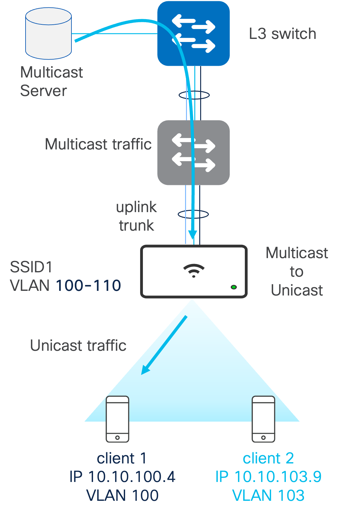
When a single SSID is used and mapped to multiple client VLANs via AAA policies, IP multicast separation may be required across the client VLANs.
In the example below, clients belong to the same SSID and IP multicast separation is not configured. This results in the following behavior.
- Client 1 requests IP multicast
- IGMP query goes on VLAN 100
- Multicast traffic is received in VLAN 100
- In the air, since #1 SSID <> #1 GTK, AP sends it as broadcast and traffic is received by client 2 (on VLAN 103) as well.
- There is no multicast or broadcast segmentation in air. This applies to IPv4 and IPv6.
In order to configure IP multicast separation, ensure the multicast to unicast feature is enabled. This configures the MRs to “de-multicast” traffic over the air to preserve the VLAN segmentation.
Note: Currently mDNS traffic is not converted from multicast to unicast.
mDNS
mDNS is supported and allows Bonjour services to work across multiple VLANs. You can also choose specific services to enable Bonjour forwarding for a limited subset of services (e.g., only for AirPlay). Please note that location-specific filters are not supported.
For more information, please see here: https://documentation.meraki.com/MR/Client_Addressing_and_Bridging/Bonjour_Forwarding
IPv6 Infrastructure
For IPv6, MR only supports Static IP and SLAAC. There is no support for DHCPv6.
Client IPv6 addressing is supported with caveats:
- Support for 802.11r/OKC over IPV6 infrastructure.
- Distributed Layer 3 Roaming is supported only if an IPv4 infrastructure is used.
- WPN support is supported with the MR 30 release.
For more information, please see here: https://documentation.meraki.com/MR/Other_Topics/IPv6_Support_on_MR_Access_Points
SSID Configuration
Meraki Wireless SSIDs can be configured in three different modes to meet customer needs. The three modes are:
- Tunneled SSID: All the traffic for the SSID is tunneled back to a central Meraki MX, and the MX will make all the switching decisions for the traffic. This is similar to the central switching deployments with a WLC. The deployment is typically used in a central switching environment to simplify wireless client deployment or, if compliance mandates, the use of a central tunnel.
- The MX model used is based on the size of the wireless deployment. There are a variety of cloud-based and hardware-based models that meet different scales. The VPN tunnel scale needs to be considered to determine the correct size. For each AP, there will be one tunnel per tunneled SSID.
- If there are 100 APs that each broadcast two tunneled SSIDs, the MX will need to support 200 tunnels just for the wireless infrastructure. If the Meraki SD-WAN Auto-VPN solution is also deployed, the number of Auto-VPN and tunneled SSID tunnels must be considered.
- The MX must be configured in a passthrough mode, and the SSID can be either in split tunnel (only relevant traffic is tunneled back to the MX) or in full tunnel (all traffic is tunneled back). A VLAN ID will also need to be configured for the SSID.
- When using the MX, the HA requirements will need to be defined. If zero downtime must be achieved, the MX must be designed with HA in mind. Otherwise, if the MX goes down, then the APs will stop broadcasting the tunneled SSID.
Note: Given this mode's scale and performance limitations, Tunnel mode is not recommended for an Enterprise deployment.
- Distributed SSID: All the traffic for the SSID will be switched locally by the MR APs. This is similar to the FlexConnect Local Switching deployments. The segmentation rules will be done at the SSID and applied by the AP. There will typically be central policy-based routing rules that will determine the next hop designation.
- Remote Worker Deployment: This is a mix of both the tunneled SSID and distributed SSID. The corporate traffic will be tunneled back to an MX placed in the data center so employees can access corporate resources easily and securely from home. The MR will also be able to broadcast a distributed SSID for the employee’s personal network that will be switched locally by the MR and sent through the employee’s home router.
It is recommended to configure no more than 3 SSIDs per AP, and there is a maximum of 15 SSIDs that can be configured per Meraki Network.
If more than 3 SSIDs are configured in a Meraki network, AP tags can be configured to specify which APs should broadcast specific SSIDs. This is like the Policy Tag on Cisco Catalyst 9800 WLCs or the AP Group on Cisco AireOS WLCs.
For more information, please see here: https://documentation.meraki.com/MR/Other_Topics/Using_Tags_to_Broadcast_SSIDs_from_Specific_APs
Note: One SSID will always be reserved for the Mesh SSID, so regardless if wireless meshing is enabled or disabled, users will only be able to configure 15 total SSIDs.
Bridge Mode SSIDs
Configuring the SSID in bridge mode is recommended for large-scale centralized or distributed deployments. The APs will work transparently, performing neither DHCP nor NAT. This provides L2 connectivity to the LAN and allows the organization’s DHCP server and NAT router to handle all the client traffic. When put in bridge mode, the client traffic must be tagged with the correct VLAN so the appropriate actions can be applied to the traffic.
Please be aware that bridge mode SSIDs only allow communication on the same VLAN, so Distributed L3 Roaming or L3 with a concentrator will be necessary to roam between subnets. However, there will be additional overhead involved with these configurations, so they are not ideal for a completely seamless roaming experience.
For more information on Bridge mode SSIDs, please see here: https://documentation.meraki.com/MR/Client_Addressing_and_Bridging/SSID_Modes_for_Client_IP_Assignment
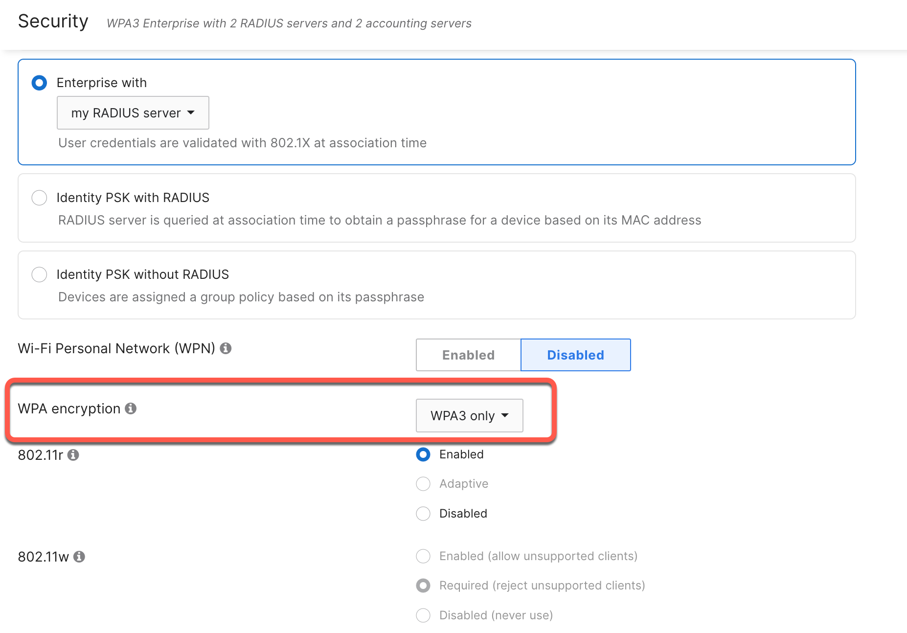
6 GHz WPA3 design
With the release of Wi-Fi 6E and the 6 GHz band, stricter WLAN security measures are now required. For an SSID to be broadcast in 6 GHz, it is mandated to configure the following:
- WPA3 for the layer 2 security. This can be either:
- OWE
- SAE
- 802.1X SHA256
- Protected Management Frame (PMF) enabled.
- No non-WPA3 L2 security method is allowed (i.e., no mixed mode is possible)
Because of the above requirements, most current WLAN deployments may not support broadcasting in 6GHz. To solve this, there are three recommended migration paths:
- “All-In” Option: Reconfigure the existing WLANs to use WPA3 (one SSID for all three radios 2.4/5/6 GHz)
- “Multiple SSIDs” Option: Redesign the WLANs to have specific WLANs/SSIDs with specific security settings
- “One SSID” Option: Coming in the MR31 release, a single SSID can be configured with transition mode (WPA2 + WPA3) on 2.4GHz/5GHz and WPA3 only on 6GHz. More information to come when the feature is released.
"All-In" Option
For customers with complete control over all the end-user devices that connect to the network, this path is highly recommended as it will provide the maximum level of security with WPA3. However, if the device types cannot be controlled (Bring Your Own Device (BYOD) environments like universities), it is not recommended to use this option because devices that do not support WPA3 will no longer be able to connect.
Going with the All-In option will also be the cleanest regarding broadcasting SSIDs. Limiting the number of SSIDs to only those supporting 6GHz will not only reduce the number of SSIDs that users need to remember to use, but it will also help reduce the overall channel utilization since each SSID will need to send out beacons and probes at the minimum data rates for the network.
For more information about Multi-SSID deployments, please see here: https://documentation.meraki.com/MR/Wi-Fi_Basics_and_Best_Practices/Multi-SSID_Deployment_Considerations
To configure a WPA3-only SSID, go to the Access Control page for the required WLAN and select the security method needed. For WPA3 encryption, select WPA3 only.
"Multiple SSIDs" Option
For most customers, the Multiple SSID option will be the recommended migration path for 6GHz WLAN design. This will allow customers the flexibility to design the WLANs for each specific use case. A wider range of devices will be able to connect, especially if the customer cannot control the types of devices that will connect.
Within this path, there are two options:
a) Add a separate WLAN with a different SSID name for WPA3 and broadcast it in all bands. Leave the existing WLAN/SSID untouched.
b) Redesign the WLANs, reserving each band for a specific device/use case.
Option A
In this option, the existing SSID will be left untouched for legacy clients and broadcast in 2.4/5 GHz for legacy clients. The new SSID will be configured solely with WPA3 and a new name and broadcast in all bands.
Note: While the new SSID name can be anything, it’s recommended to make the new SSID name similar to the existing SSID name for easier end-user experience. For example, if the legacy SSID name is internal, the new SSID should be named internal-WPA3. In any case, outreach and education are highly encouraged to have users move to the new SSID.
Option B
In this option, all the existing WLANs will be redesigned. Each SSID will be broadcast on a specific band for a specific device type / use case.
The 2.4 GHz band is dedicated to specific devices. These could be legacy devices or IoT devices if IoT will be mostly PSK. 5GHz band is dedicated to most existing clients, while WPA3 will be on the 6 GHz band only for the newest clients.
VLAN planning
When designing the VLANs and subnets for the clients, please follow the best practices outlined in the DHCP section above.
Some general recommendations for client VLANs are:
- VLAN broadcast domain rules apply
- /24-/20 subnet sizes
- Enable wireless multicast-to-unicast
- Consider separating VLANs
- Example: Create a Service VLAN for printing resources for visitors
- Use tag based VLAN and/or SSID assignment
- For the MR30 release or later, configure Named VLAN / VLAN pooling for larger client VLAN sizes.
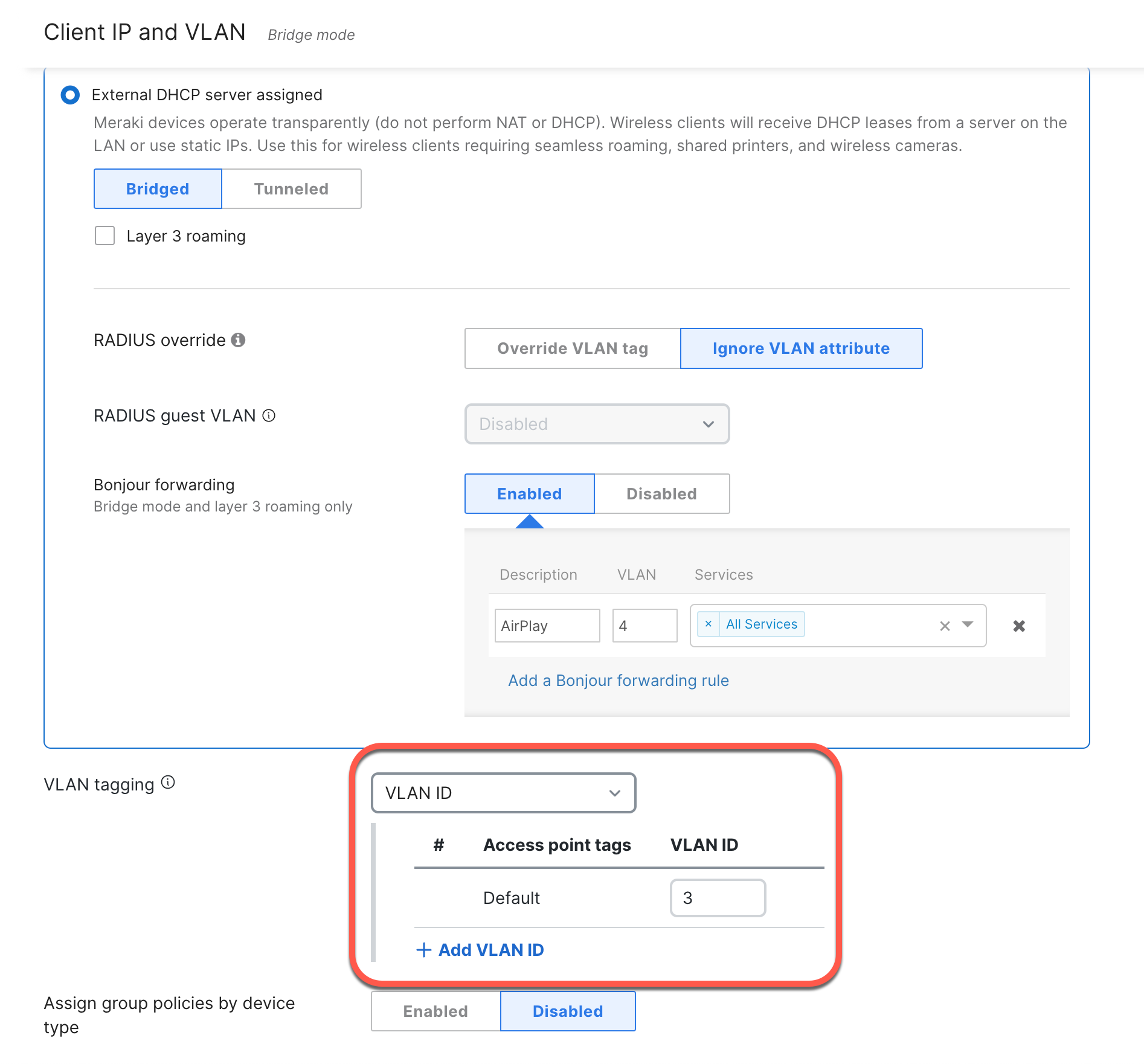
Per-SSID VLAN Tagging
To allow for VLAN tagging of wireless clients and to allow for their traffic to reach the rest of the network, the following configurations should be done on the switchports connecting the access switch to the AP:
- The switch port the Cisco Meraki AP is connected to should be configured as an 802.1Q trunk port.
- The trunk port should be set to allow all the VLANs that will be tagged on each SSID.
- Each SSID in Dashboard should be tagged with a routable VLAN and configured throughout your local switching architecture.
- VLAN tagging is only available under External DHCP server assigned, which is a feature available to Enterprise customers.
Named VLAN / VLAN Pooling
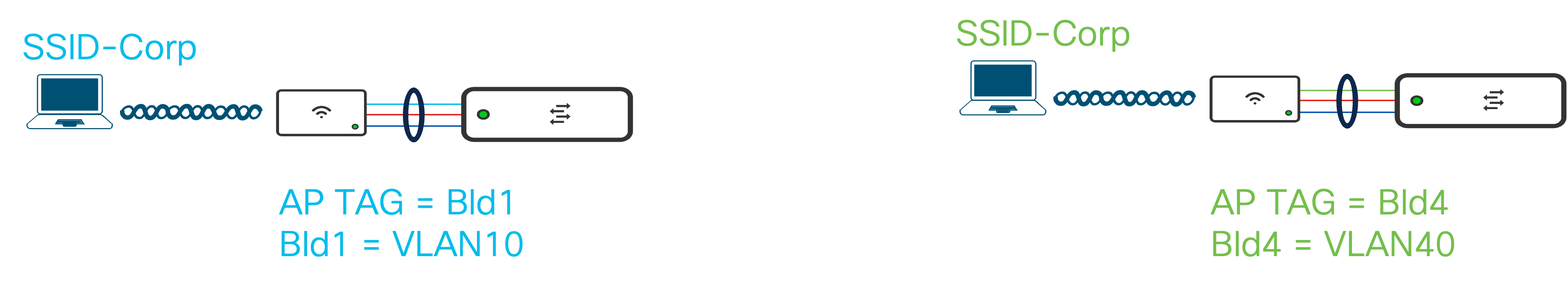
Starting with the MR30 release, Meraki Wireless supports using Named VLAN and VLAN Pooling for wireless clients. Configuring Named VLANs provides dynamic, RADIUS-based assignment of VLANs to devices/users/endpoints based on an alphanumeric name instead of an integer number. This is especially useful in large-scale deployments where users are segmented and assigned to specific VLANs from the AAA server, but the VLAN ID number changes per site.
Let’s take the example below.
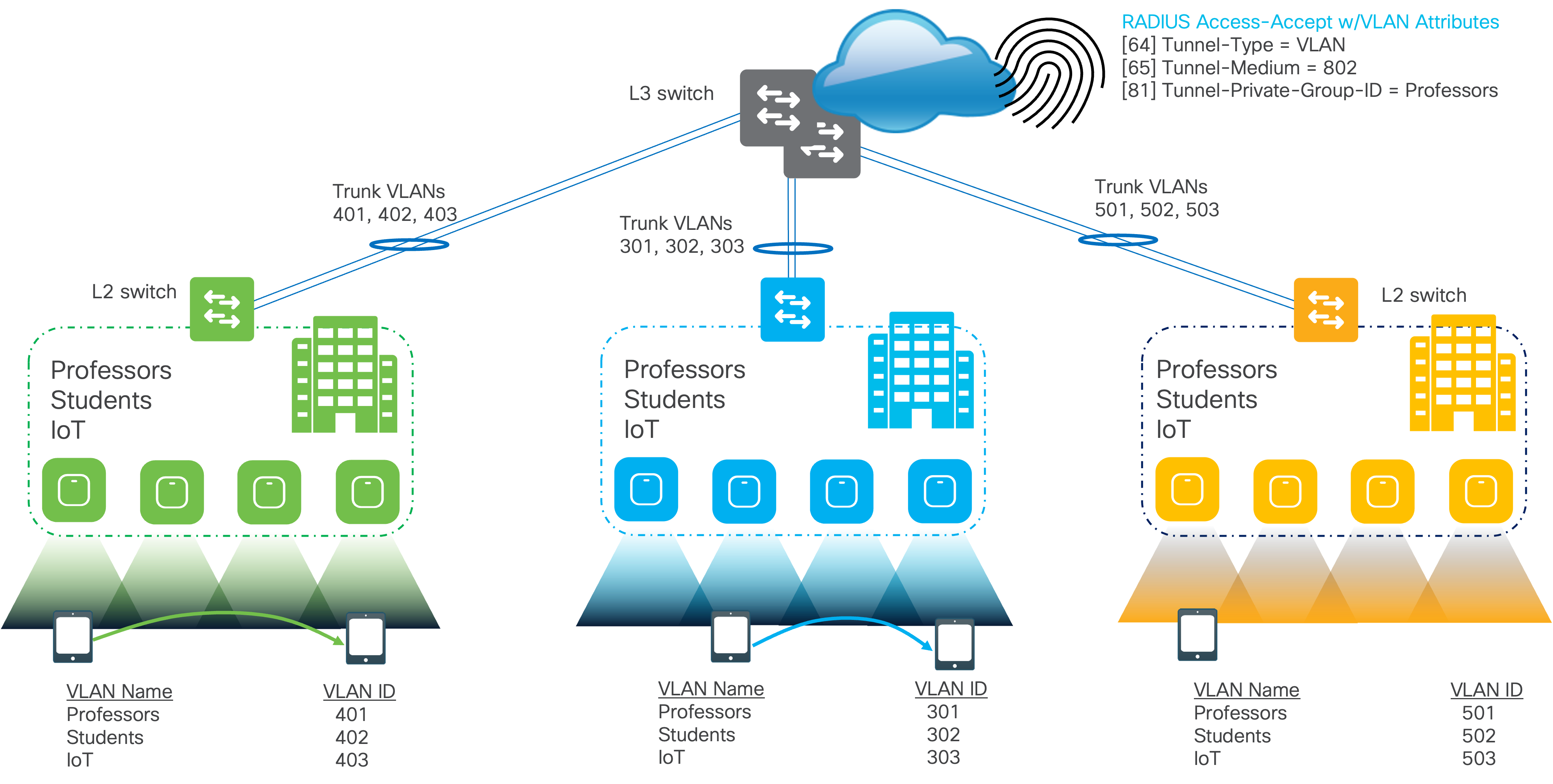
Regardless of the sites, the client segmentation stays the same. The Professors, Students, and IoT are all in their own specific VLAN, but the exact number changes based on the site. The Green site puts the Professors into VLAN 401 while the Blue site puts them in VLAN 301. If assigning the VLANs by an integer number, network admins must create specific RADIUS Access-Accept Profiles per user per site to account for each VLAN ID. While in the example above, there would only need to be nine profiles created (three profiles for each user type and three sites) for larger scale deployments, this number could get exponentially large, increasing the management overhead. Changing the properties of one user type could mean that the same change needs to be applied to all the other profiles associated with that type.
Note: For Named VLAN support with AAA Override and 802.11r, MR must be running the MR30 release or later.
To reduce the management overhead, named VLANs are used to assign user VLANs by name. Now, in the AAA server, the number of RADIUS Accept Profiles is only based on user type. Each profile, based on the user type, can then be reused for each site. Returning to the Professor VLAN example, the RADIUS Access-Accept Profile now assigns professors to the VLAN named Professors. As long as the given site has a VLAN named Professors, the professor users will be placed in the correct VLAN regardless of whether the VLAN ID number is 401 or 301.
Configuring VLAN Pooling allows customers to scale the number of wireless clients the network supports without drastically increasing the broadcast domain. Pooling different VLANs together also allows customers the flexibility to use the subnet design they choose. Rather than redesigning the subnets to account for large numbers of wireless clients, customers can easily pool multiple subnets together as they scale. VLAN Pooling is supported for all authentication types and does not require RADIUS.
For more information, please see here: https://documentation.meraki.com/General_Administration/Cross-Platform_Content/VLAN_Profiles#MR_Named_VLAN_.2F_VLAN_Pooling
AP Tags
AP Tags are a great way to segment or partition groups of MRs within the same Meraki Network based on different use cases and needs. Some examples of this can be:
- Tag-based RF Profile Assignments
- APs in a classroom vs APs in an auditorium
- Ceiling vs wall mount APs
- More easily run search, report, and analytic filters on specific groups of APs
- SSID Availability: Broadcast SSIDs based on APs for a certain length of time
- Ex. Guest SSID only broadcasted by lobby APs from 8 am to 5 pm on weekdays.
- VLAN Tagging: Different VLANs are applied for the same AP based on the AP tag
For more information on creating AP tags, please see here: https://documentation.meraki.com/MR/Monitoring_and_Reporting/Using_Tags_to_Manage_MR_Access_Points
For more information on using tags for SSID availability, please see here: https://documentation.meraki.com/MR/Other_Topics/Using_Tags_to_Broadcast_SSIDs_from_Specific_APs
Quality of Service Guidelines
QoS can play an important role in your network as it helps prioritize and reliably deliver certain types of data using the Differentiated services model. "DiffServ" implements the prioritized model by marking packets according to the type of service they desire. In response to these markings, access points, routers, and switches use various queueing strategies to tailor performance to expectations.
Some general guidelines when configuring the QoS for your wireless networks are:
- SSID
- Set the SSID to prioritize a type of traffic (e.g. VoIP and video conferencing)
- Switching Infrastructure
- Define and match the DSCP values that are used by the SSID and the rest of the network.
- WAN Infrastructure
- Keep the QoS policies between the different sites consistent
- Apply the policies for bidirectional traffic.
When shaping the traffic on the SSID for clients and applications, the types of traffic and their requirements should be considered. The traffic shaping should not be done as a top-down enforcement for the entire SSID. Instead, traffic should be shaped per client followed by per application.
In the case of guest networks, it may be necessary to apply bandwidth throttling policies. For these guest clients, you must understand their workload and the average bitrate needed before applying any shaping rules. After determining the required bandwidth limit, apply this to the per-client bandwidth rules. Enable SpeedBurst as well to allow for a graceful traffic shape, so users can go past their allotted bandwidth temporarily to access any services or download small files without a degraded experience.
Note: When applying bandwidth throttling policies, be aware there may be an inverse effect on airtime utilization as now the clients will take longer to complete their workloads.
For applications, mission-critical applications can be derestricted and prioritized, while recreational applications or bandwidth-hogging applications can be restricted. These applications can be chosen based on the deployment use case. For example, video conferencing and collaboration applications can be prioritized along with the industry-specific applications while simultaneously restricting the performance of applications like peer-to-peer and cloud backup / OS updates.
For more information, please see the configuration guide on traffic shaping here: https://documentation.meraki.com/MR/Firewall_and_Traffic_Shaping/Traffic_and_Bandwidth_Shaping
Application Visibility and Control (AVC) Policy Behavior
The Application Visibility and Control policy (DSCP marking, traffic rate limiting, etc.) exists both on the roam-from and roamed-to AP. However, the client flow state is not transferred upon roaming (as of today). The result is that the flow might get the policy applied on the AP it initially associates, but then the policy is no longer applied after roaming. In the example below, a rate-limiting policy is applied for Windows File Transfer, resulting in slower transfer speeds. Once the client roams to a new AP, the rate-limiting policy is no longer applied.
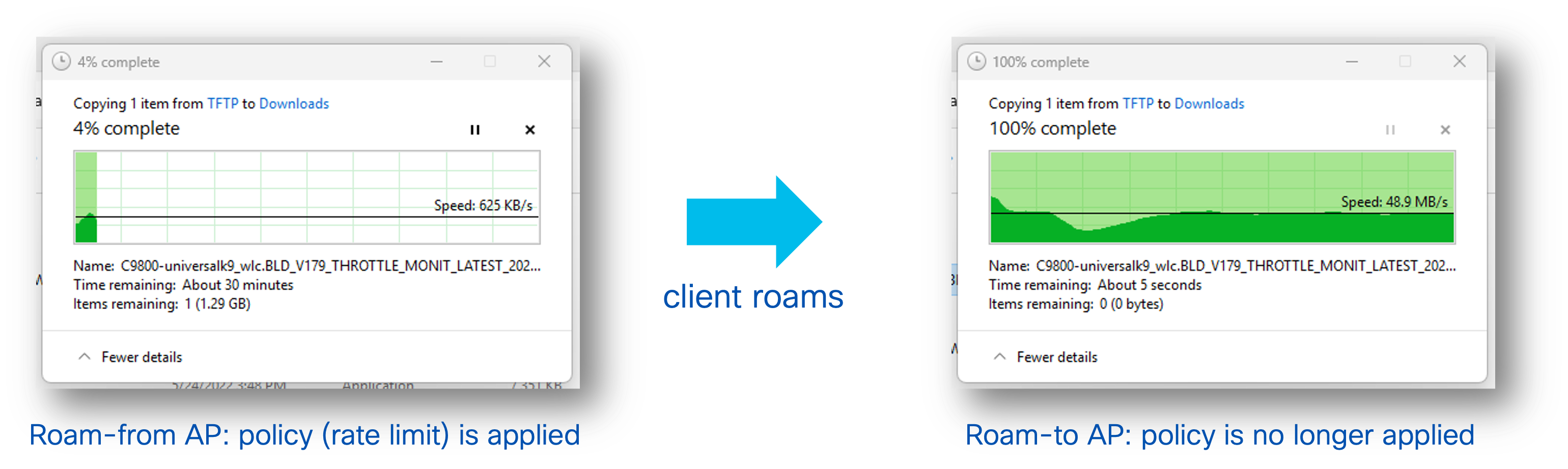
For this behavior to happen, the application cannot be recognized (e.g., encrypted), so that the roam-to AP cannot classify it and cannot apply the policy. Also, most browser pages and applications are made of multiple sessions so any new flow started on the roam-to AP will be correctly classified.
Access Point Radio Configuration
Client Load Balancing
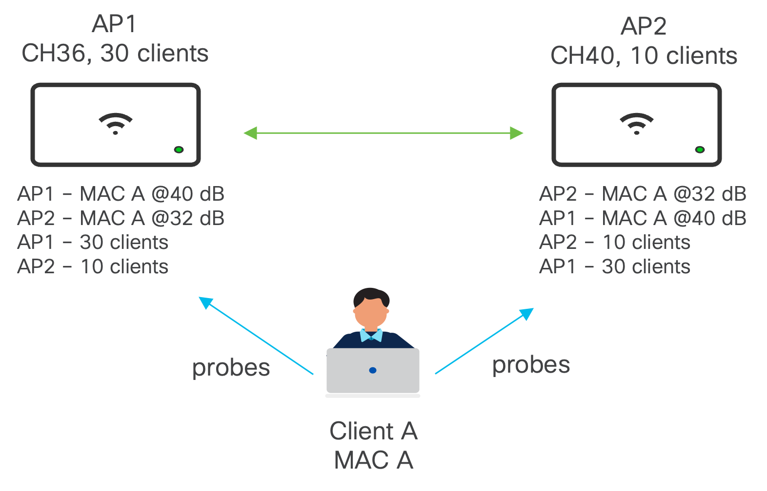
Client balancing uses information about the state of the wireless network (AP and clients) to steer the client to the best available access point. This is done via 2 methods: active and passive.
- Passive: At client association, based on probes and association rejection
- Active: At client association but also post association and only for 802.11v-capable clients using BSS-TM frames (MR 29 or higher)
The Client Balancing information is shared between APs using L2 broadcast messages on UDP port 61111.
For high-density deployments, the recommendation is to turn off Client Balancing as the amount of processing due to probes could overwhelm the network. Because of this, Client Balancing is turned off by default for newly created Meraki Networks
Wireless Mesh Networking
If wireless mesh deployments are not needed, it is recommended to set the Meshing settings to Meshing disabled. This will stop the MR from broadcasting the Mesh SSID, which will save airtime.
For more information, please see here: https://documentation.meraki.com/MR/Wi-Fi_Basics_and_Best_Practices/Wireless_Mesh_Networking
AI-Powered Auto RF
Auto RF
Auto RF is a feature on Meraki access points that are built on Auto TX Power and Auto Channel to detect non-Wi-Fi interference and monitor the Wi-Fi environment to adjust and optimize radio settings in real-time. Based on the environmental factors it detects, Auto RF can automatically tune settings such as channel assignments, per-radio transmit power, and band steering.
This works on a Meraki Network basis, so APs that are RF neighbors should be part of the same Meraki Network. This will ensure an optimized channel and power plan. The best practice is to have around 500 APs per Meraki Network with a recommended maximum of 800 APs. Howver, this is not a hard limit.
In the cases where the number of APs exceed the recommendation and cannot be placed in the same Meraki Network, split the APs based on the fast roaming domain or common RF domain.
For more information, please see here: https://documentation.meraki.com/MR/Monitoring_and_Reporting/Location_Analytics/Meraki_Auto_RF%3A__Wi-Fi_Channel_and_Power_Management
Auto Busy Hour
The busy hour feature will avoid unnecessary RF changes during the defined period and make the essential changes after the busy hour. Meraki Dashboard will automatically detect the busy hour by processing the historical utilization of the customer network. If needed, the busy hour can be manually set by the customer. This will help minimize eliminate client disconnections or roaming due to channel changes.
Each business vertical has its own characteristic of busy hours, and sometimes it is hard to dictate from the central network admin perspective. Auto Busy Hour should be Enabled, so Auto RF can automatically optimize each network individually for its unique busy hour daily.
AI Channel Planning
A well-designed channel plan will ensure we get the most out of the RF network to operate for high-performance wireless network. This can be achieved by having a wide spread of channel availability in the AutoChannel list. But these channels get affected by DFS events and Non-Wi-Fi interferers like Jammers, which reduces the number of channels that can be used for Wireless network operations effectively. AI Channel Planning should be Enabled, so Meraki Dashboard will maintain the channel avoid list for individual Access Points in the network.
AI Channel planning essentially will avoid channels that are most affected by the following reasons:
- • Too frequent DFS events
- • Too frequent Jammed channel
- • AFC low power regulation (outdoor 6 GHz AP)
Please see the configuration guide for AI-Powered Auto RF here: https://documentation.meraki.com/MR/Radio_Settings/AI-Powered_Auto_RF%3A__Use_AI_to_Bring_Meraki_Towards_RF_Excellence!
Infrastructure Management
Firmware Updates
Cisco Meraki has always prided itself on delivering powerful networking and IT solutions in a simple, easy to manage fashion. This extends to firmware management on Meraki devices. Traditionally, firmware management is a tedious, time-consuming, and risky procedure met with dread and loathing by the network administrator tasked with carrying out the upgrades, but Meraki works to limit this burden. Complexity has long plagued firmware management practices throughout the industry, spawning horror stories about experiences such as upgrades that went sideways because of a corrupted USB drive or late nights in data centers manually provisioning the new code.
Meraki tackles the complex firmware issue by leveraging the power of Meraki’s cloud-based dashboard to allow for easy deployment and firmware scheduling. The dashboard provides unique insights into new features as they become available in new firmware releases.
The simplicity provided by the cloud gives customers the ability to choose which firmware they want to run for each network and when to schedule the upgrade. With that said, there are some recommendations that should be followed for the best wireless experience.
- All MRs within the same roaming domain should run the same MR version to allow for consistent features and compatibility among the MR while roaming.
- Keep Try beta firmware set to No on production networks to avoid beta firmware from automatically being installed on the network before being validated.
- When upgrading to a new firmware version (typically a new stable release or beta release), designate a specific MR test area and move these APs into a specific test network. Here, you can validate the new firmware version without affecting the rest of the network. The test network should be a non-business critical area where there will be a diverse and large enough group of clients that will join the network.
- The firmware upgrade strategy should consider whether clients will still be connected during the scheduled upgrade time.
- Clients need to stay connected: Choose Minimize Client Downtime. The APs will download and upgrade to the new firmware in a staggered fashion to be less disruptive to clients. The staggered upgrade will be slower but allow clients to stay connected.
- Clients do not need to stay connected: Choose Minimize Total Upgrade Time. All the APs will download and upgrade to the new firmware at the same time. This will result in faster upgrade times at the expense of connectivity loss of all wireless devices.
For more information on Best Practices for Meraki Firmware, please see here: https://documentation.meraki.com/Architectures_and_Best_Practices/Cisco_Meraki_Best_Practice_Design/Best_Practices_for_Meraki_Firmware
For more information on Access Point Firmware Upgrade Strategy, please see here: https://documentation.meraki.com/MR/Other_Topics/Access_Point_Firmware_Upgrade_Strategy
Features that Need Support to Enable
Unless otherwise stated, all features can be configured from Meraki Dashboard. For some features, Meraki Support will need to enable your organization to be able to use these features. In these cases, this will be clearly marked on the feature’s configuration guide like the note below.
Note: If this section does not appear, open a case with Cisco Meraki support to have it enabled.