
Advanced MS Setup Guide
Making changes to your switched network, switches or switch ports can cause significant downtime, please schedule accordingly.
For technical assistance, please reference our documentation or contact Meraki Support.
Default configuration
MS series switches have a default (out of box) configuration. This configuration is as follows:
- All interfaces are configured as TRUNK with Native VLAN 1
- All interfaces support 802.1Q trunk encapsulation
- All interfaces will send management traffic on VLAN1 (untagged)
- All interfaces have STP/RSTP enabled
In order for Meraki switches to update their configuration and/or firmware, each switch must have a valid IP address, default gateway, and must be able to send management traffic. Each switch must also be able to contact Meraki cloud services. For further information, please see Firewall Information.
Note: If your network does not have a DHCP service running on the default management VLAN, a static IP and/or different management VLAN must be manually configured. Please see the article titled Using the Cisco Meraki Device Local Status Page for more information.
Management VLAN
By default, Meraki switches are configured to use VLAN 1 for untagged and management traffic and all switch interfaces are configured as trunk native VLAN 1. Modifying the VLAN used for management traffic can be done via the local configuration page per switch or globally via the Meraki dashboard:
Meraki Dashboard
Globally
Navigate to Configure > Switch settings and specify the desired VLAN in the "Management VLAN" section.
Per Switch
Navigate to Monitor > Switches and select the desired switch. Now, choose "Set IP address" for the LAN IP field. From here, you can specify the switch's management VLAN.
Please allow a few moments for the configuration change to propagate. This requires that your MS switch(es) are online and reporting to the Meraki cloud.
Firmware upgrade process
When adding or installing a new Meraki device, as soon as it checks in to the Meraki cloud, it will verify that the firmware version it is running matches that of it's Meraki network container. If it does not, the device will automatically download and upgrade itself to match the network version. No user intervention is needed, and the firmware upgrade process usually completes within 10 minutes with only about 60 seconds of downtime.
Meraki strives to make software upgrades as seamless and easy as possible. One of the benefits of the Meraki cloud architecture is that firmware can be delivered to one or even thousands of devices at once, automatically.
It is important to note that Meraki device firmware is maintained at the network level. This means that each network container within the dashboard has a specific firmware version, and all devices within that network container will be on that version of firmware.
Spanning Tree (STP, RSTP)
Spanning tree (IEEE 802.1D) and Rapid spanning tree (IEEE 802.1w) are both standards-based protocols. The MS series supports these protocols for maximum interoperability with other vendor switches. It is important to take note of the following deployment steps when installing an MS series switch in an existing switch infrastructure. For information on how to configure spanning tree on Meraki switches, check out our Configuring Spanning Tree on Meraki Switches article.
Root bridge
When connecting access devices including the Meraki MS series switches, it is important to first ensure that a root bridge has been properly configured. In a larger switch fabric, this is typically done on the core switch.
Spanning tree will use several values to elect the root bridge. Once elected, this information is displayed per switch in the Meraki dashboard interface under Switch > Monitor > Switches.
Automatic edge port
MS switches will automatically place all access interfaces into EDGE mode. This will cause the interface to immediately transition the port into STP forwarding mode upon linkup. The port still participates in STP. So if the port is to be a part of the loop, the port eventually transitions into STP blocking mode.
Note: MS390/C9300-M running <=12.28 firmware does not support edge-port (portfast). To utilize portfast please upgrade to 12.28.1 or any later releases.
Protocol interoperability
Several other protocols have been developed including pre-standard and non-standard protocols to either improve upon or facilitate the same functionality of spanning tree. It may be necessary to connect a Meraki MS series switch to an existing infrastructure running one of these protocols.
MSTP (802.1s)
MSTP is an expansion of RSTP and adds a per-VLAN spanning tree instance to make use of better paths on each VLAN. MSTP is fully compatible with RSTP bridges, in that an MSTP BPDU can be interpreted by an RSTP bridge as an RSTP BPDU. Meraki switches do not support MSTP but are compatible and will see all MSTP instances as a single RSTP region.
Note: The MS390/C9300-M runs single MSTP instance by default (instance 0) and is not configurable for more than 1 instance. This aligns the platform to maintain compatibility with all other MS switches running Rapid Spanning-tree.
PVST/PVST+
This is a Cisco proprietary protocol on Catalyst/Nexus switches that is compatible with spanning tree (802.1D). It is important to note however that because PVST/PVST+ is a multi-VLAN spanning tree protocol, in order for the MS series switches to participate in spanning tree a spanning tree instance must be running on VLAN 1 of all switches and VLAN 1 is allowed on all trunk ports running PVST+ so that BPDUs are seen by the Meraki switches in the topology. Connecting an MS series to an existing switch fabric running PVST+ will force the MS series switch(es) to run in legacy mode (STP) which can increase convergence time. In this configuration, the MS series switches should never be the STP Root Bridge.
Note: When connecting a PVST+ bridge to an MS series switch, make sure both ports are configured as an 802.1Q trunk. Otherwise, the PVST+ bridge will go into a blocking state due to port inconsistency. To avoid any issues with STP, it is recommended to convert the Cisco Catalyst environment to single instance MSTP. This will ensure maximum compatibility in the STP environment.
Rapid-PVST
This is a Cisco proprietary protocol on Catalyst/Nexus switches that is compatible with spanning tree (802.1D) and RSTP (802.1w). It is important to note however that as Rapid-PVST is a multi-VLAN spanning tree protocol, MS series switches can participate in spanning tree only when a spanning tree instance is running on VLAN 1 of all switches. In addition, VLAN 1 must be allowed on all trunk ports running Rapid-PVST, so that BPDUs are seen by the Meraki switches in the topology. In this configuration, the MS series switches should never be the STP Root Bridge.
Note: To avoid unexpected issues where an MS is between two R-PVST switches (such as a Cisco Catalyst Root Bridge < MS > Catalyst switch). It is recommended to convert the topology to a MSTP on the Catalyst switches. This will avoid potential port inconsistency errors and other issues that may cause instability in the STP topology.
Port configuration
Meraki switches support 802.1Q encapsulation and up to 4094 VLANs. This means that you have an option for how to configure each switch port and this is typically dependent on what is connecting to each interface. For configuration information, please reference our documentation.
Note: The MS390/C9300-M supports up to 1000 active VLANs in the environment. To support VLANs outside of 1-1000, ALL switchports on the switch must be configured with a new restricted allowed VLAN configuration on trunk ports.
Example to support VLANs 1-900, 2001-2100:
Default Trunk Configuration: Allowed VLANs 1-1000
New Trunk Configuration: Allowed VLANs 1-900, 2001-2100
Note: Cloud managed Cisco Catalyst 9200 and Cisco Catalyst 9200L Series Switches can support up to 512 active VLANs.
Trunk (interconnect) port
Interfaces between switches or gateway devices are typically configured as TRUNK to support multiple VLANs. It may or may not be necessary to specify a Native VLAN.
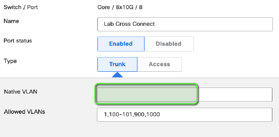
Native VLAN
Depending on how your network is configured, it may be necessary to specify a Native VLAN on a TRUNK interface. This specified VLAN will be used for all untagged traffic that enters and exits the interface. If a Native VLAN is specified, ensure that it is also added to the Allowed VLANs configuration.
NOTE: If there is a requirement to drop any untagged traffic on a trunk port, the recommended configuration is to remove the native VLAN from the trunk port e.g. leave the Native VLAN field blank. Leaving the Native VLAN field defined but not in the Allowed VLANs list may not achieve the same result.
Example of recommended configuration:
Access port
Access ports are designed for edge/access devices such as workstations and printers. Any interface configured as an access port for a particular VLAN will remove the 802.1Q header on egress and only for the configured VLAN on the interface.
Voice VLAN
This is an optional setting for all access port interfaces that will force the interface to advertise the specified voice VLAN via discovery protocols. It is designed to support multiple VLANs for deployments with VoIP phones that have a built-in switch. For more details, see Configuring a Voice VLAN
Protocol Interoperability
Several non-standard protocols have been developed to facilitate trunking or simplify VLAN change propagation. Meraki switches leverage the power of the cloud architecture to make port configuration easier than ever before and therefore do not support these non-standard protocols. However, interoperability may be required.
VTP (VLAN Trunking Protocol)
This is a Cisco Catalyst protocol that supports automatic VLAN database propagation and per-interface VLAN pruning. Meraki switches do not support VTP but will forward VTP updates, which means they operate in VTP transparent mode.
Based on network topology, there are certain key things to note about VTP interoperability. For more information, please reference our documentation.
ISL Encapsulation
This is a Cisco Catalyst protocol that is not supported on Cisco Meraki switches.
Power over Ethernet (PoE)
MS P-model switches support PoE (IEEE 802.3af) and PoE+ (IEEE 802.3at). When connecting PoE devices to an MS switch, the switch will snoop for LLDP and LLDP-MED power information. If the connected device supports LLDP, the switch will supply only the advertised power to the connected port, thus adding intelligence to per-port power budgeting. This information can be seen via Monitor > Switches by selecting the desired switch and port.
Over-budget behavior
If exceeding available PoE power, Meraki switches use a shedding algorithm based on interface number. The highest interface count (highest port number) to draw power and exceed PoE budget will no loger receive PoE power on that interface.
Pre-standard PoE
The following P-model switches can support Cisco pre-standard PoE (inline power): MS22, MS42, MS220, MS320, MS350
Switch stacking and redundancy
Enterprise deployments often require resiliency which is done through redundant physical connections and facilitated by software protocols.
Meraki switches support STP/RSTP which allow for several physical connections to coexist. In order to set up redundant connections, confirm that STP/RSTP is properly configured and enabled on your interconnect switch interfaces.
Additionally, LACP link aggregates can be easily configured to provide additional cable redundancy between switches. See Link Aggregation for more details.
For additional information on stacking Meraki switches, please view the Virtual Stacking whitepaper.
Selecting Accessories
Depending on your infrastructure needs and deployment requirements, selecting the proper accessories is key. For selecting the appropriate accessories for your SFP/SFP+ ports, it is recommended that you reference the SFP datasheet.
For interconnecting MS switches with SFP+ interfaces (MS42 / MS42P), Meraki recommends the use of Direct Attach (twinax) cables.