
MT11 Probe Sensor Installation Guide
Overview
The Cisco Meraki MT11 is a cloud managed Probe based sensor that is exceptionally simple to deploy and configure due to its integration into the Meraki dashboard and the use of BLE technology. The MT family eliminates the complex and costly setups required by traditional solutions which removes the limitations of placement of these sensors.
Product Overview
Physical Specifications
|
Dimensions |
117.1x65.7x23.3 mm (LxWxH) |
|
Power |
|
|
Operating Environment(Body Only) |
|
|
Hardware |
|
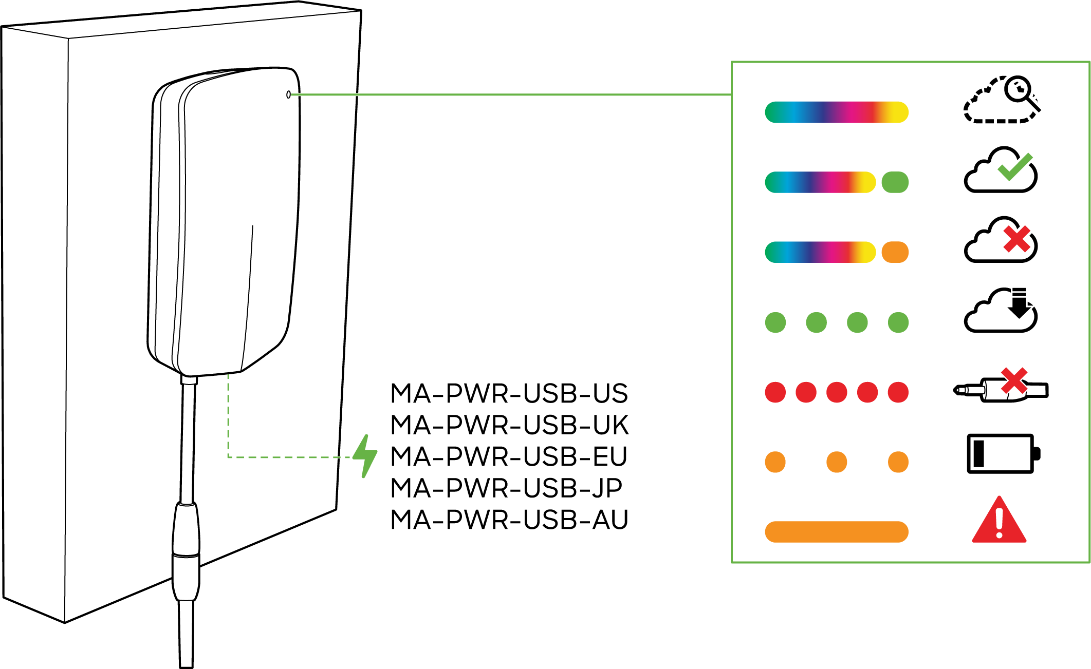
LED Indicators
-
Rainbow - MT is initializing or looking for a gateway.
-
Solid Green(for n seconds) - Connected to a gateway.
-
Solid Amber(for n seconds) - MT could not find a gateway to connect.
-
Flashing Green - MT is upgrading its firmware
-
Flashing Red - Incorrect Probe connected to MT11
-
Flashing Amber - MT is running on a low battery.
NOTE: To conserve battery life, the LEDs on the MT11 are not always on.
General Purpose Button
The MT11 has a general purpose button on the top which allows you to wake up the sensor and test if it is able to connect to a gateway.
Factory Reset Button
Next to the battery compartment, there is a pinhole button to factory reset the sensor. If the button is pressed and held for at least five seconds and then released, the sensor will reboot and it will be restored to its original factory settings by deleting all configuration information stored on the unit.
USB-C Port
The MT11 sensors have a USB-C Port on the bottom that can be used to provide an alternate source of power using a compatible accessory:
- MA-PWR-USB-XX - USB-C Power adapter
- MA-PWR-ETH - USB-C to PoE adapter
Probes
On the bottom of the MT11 sensors there’s a 3.5mm receptacle on a pig tail that can support a variety of probes. Please refer to MT11 Probes for more information on the types of probes.
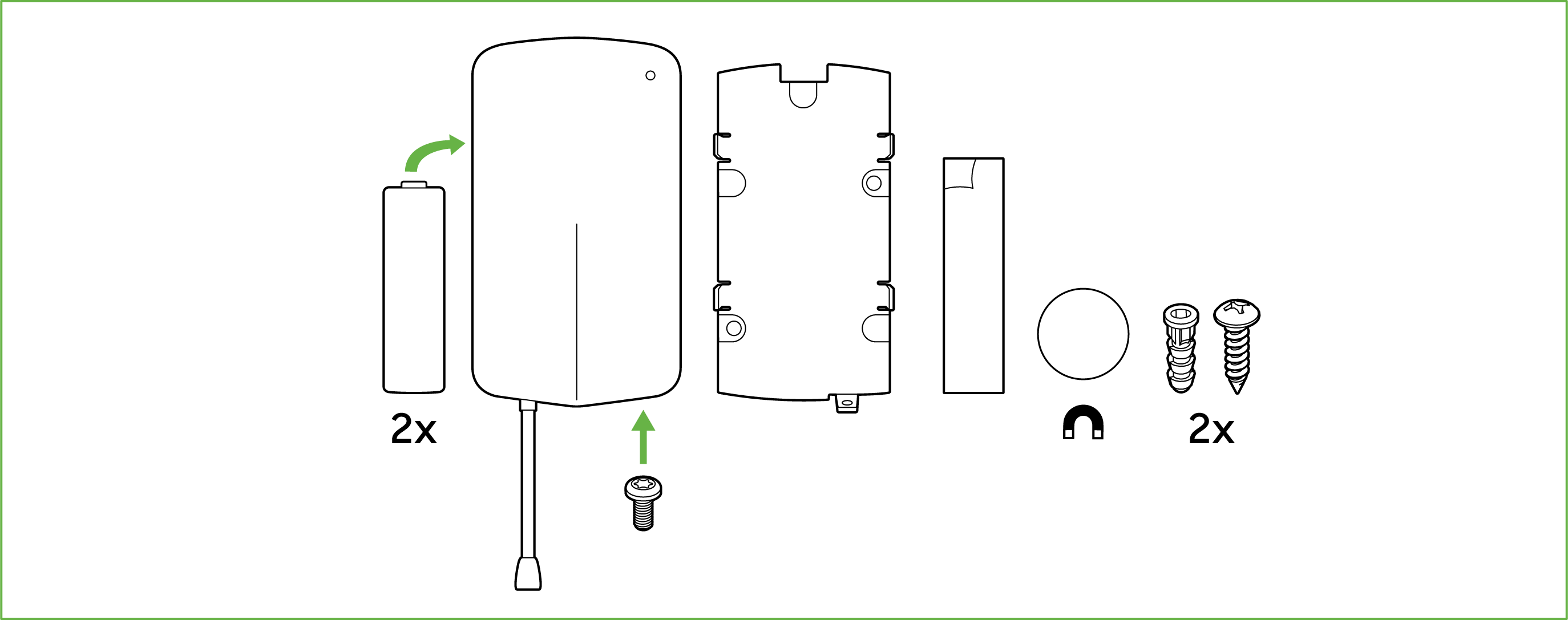
Package Contents
|
Unit |
MT11-HW |
|
Guides |
QIGs |
|
Battery |
2 AA Batteries |
|
Mounting equipment |
Screws 2xMagnet 1xVHB Tape |
Probes for MT11 are sold separately and are required for the sensor to function.
Pre-Installation Preparation
You should complete the following steps before going on-site to perform an installation
Configure Your Network in Dashboard
The following is a brief overview only of the steps required to add an MT11 to your network. For detailed instructions about creating, configuring and managing Meraki Sensor networks, refer to the online documentation (https://documentation.meraki.com/MT).
-
Login to http://dashboard.meraki.com. If this is your first time, create a new account.
-
Find the network to which you plan to add your sensor or create a new network.
-
Add the sensors to your network. You will need your Meraki order number (found on your invoice) or the serial number of each sensor, which looks like Qxxx-xxxx-xxxx, and is found on the back of the unit or included in the box.
-
Add the gateway(MV or MR) to the same network as the sensor.
WARNING:
Make sure the gateway is in the same network and is online and operational. If the sensors are powered on without a functioning gateway in the immediate vicinity, the sensors will consume power at a high rate until it finds a gateway.
Click here for MV setup instructions and MR setup instructions.
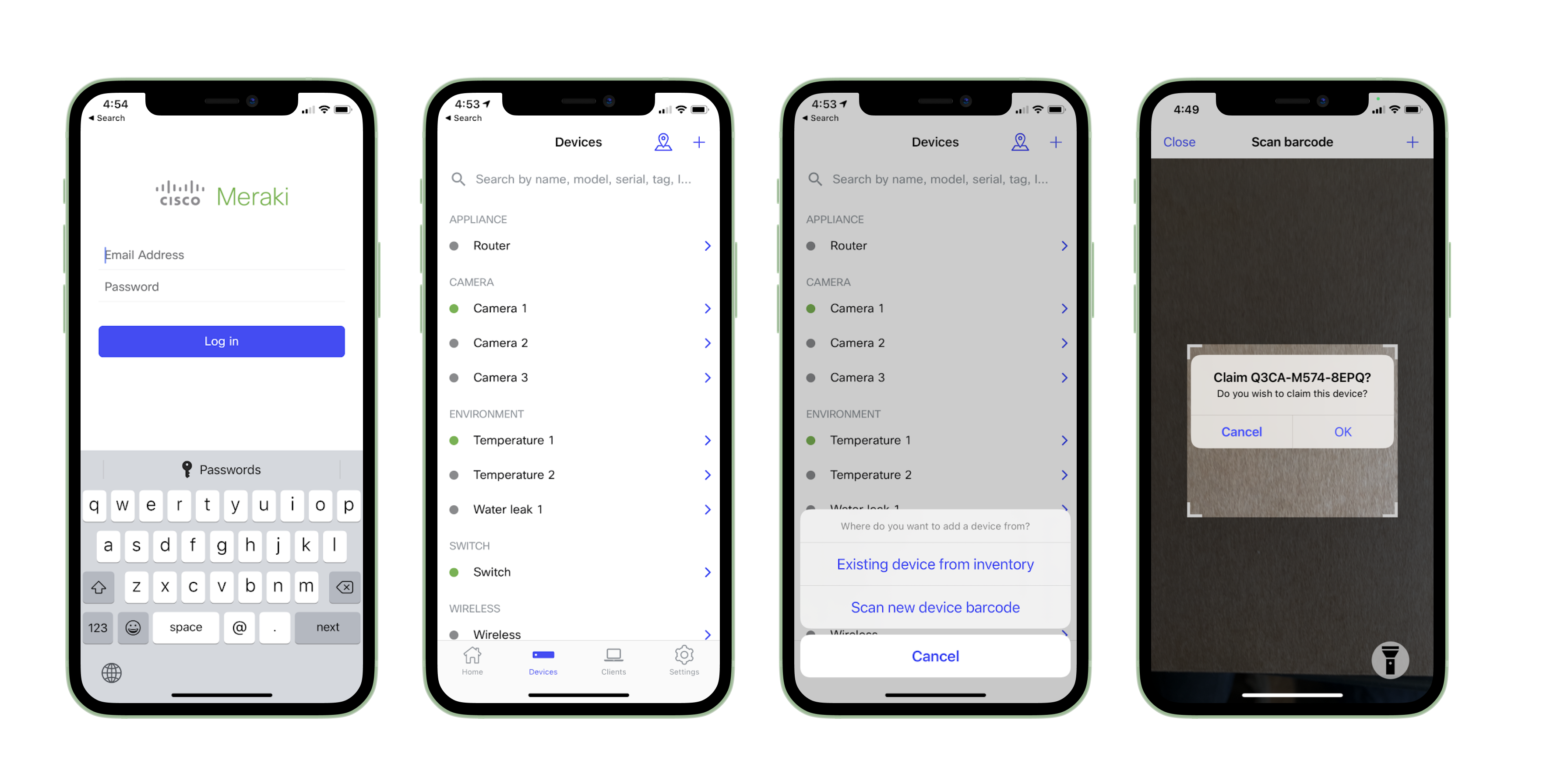
Quickly Scan and Claim Multiple Devices through the Meraki Mobile App
If you have to claim multiple devices, the quickest way is by scanning their barcode using the Meraki app.
- Log in to your Meraki iOS or Android app with your Meraki dashboard account. Create a new account if you do not have one.
- Navigate to the correct network through left-side bar.
- Go to the Devices tab from the bottom navigation bar.
- Select the + icon on the top right of the screen and pick Scan new device barcode.
- Point your phone camera toward the hardware barcode to claim the device.
- Enter device information and then select Done. Press Add another to claim a new device.
Installation Instructions
NOTE: Each MT11 comes with an instruction pamphlet within the box. This Quick Install Guide (QIG) contains detailed step by step guides and images to assist you in the physical installation of the sensors.
Choosing Your Mounting Location
The MT11 Probes are primarily targeted to monitor wider temperature ranges compared to the MT10 with the onboard temperature sensor. Keeping that in mind, the probes are intended to be installed within a colder environment while the body stays in a location where the operating temperature is maintained.
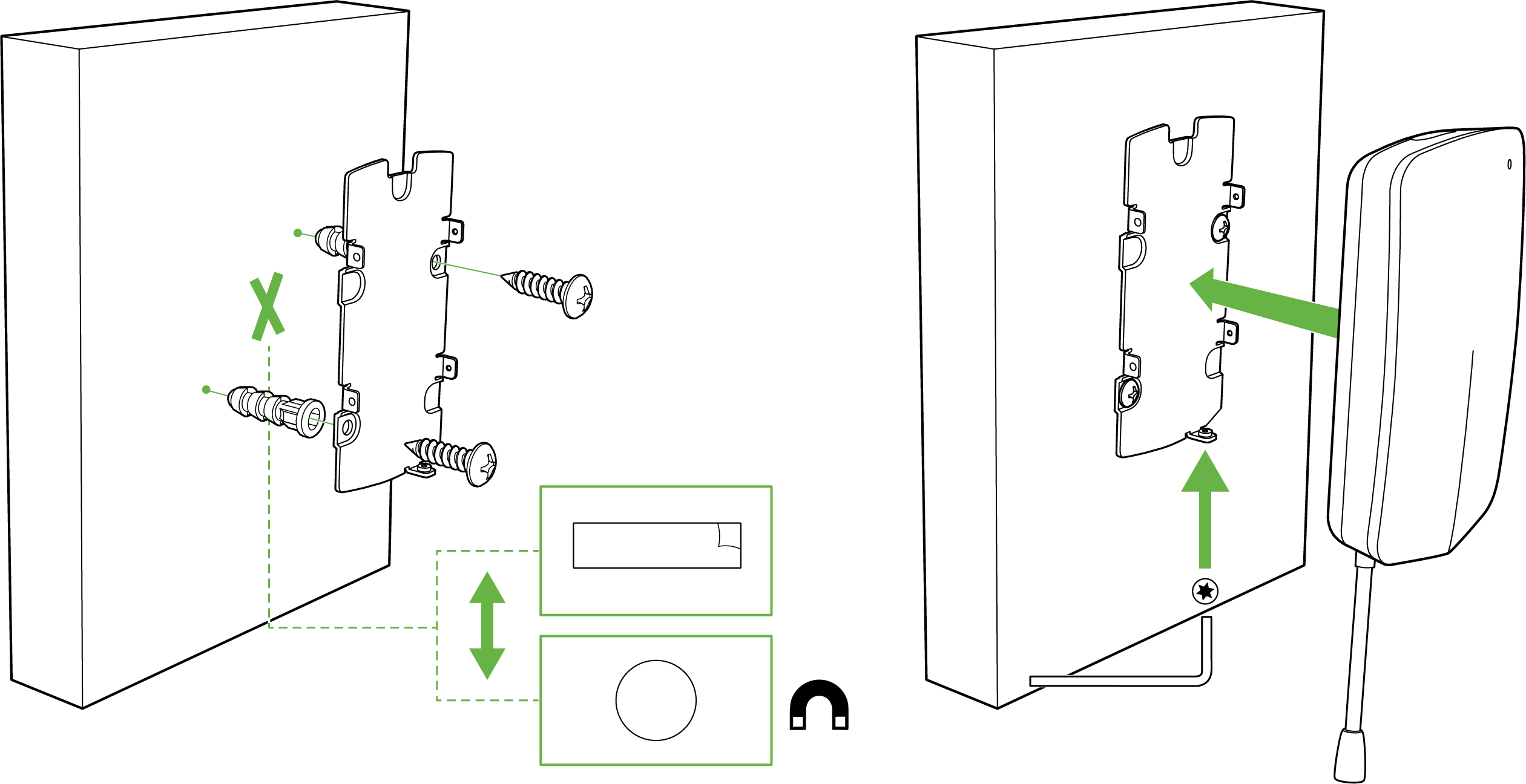
MT11 Body Installation
For most mounting scenarios, the MT11 has flexible options to provide quick and simple mounting. The instructions are as follows:
-
As the AA batteries come pre-installed, start by removing the Pull Tab to turn on the sensor.
-
In order to mount the sensor on different locations, there are 3 options
-
Screws - The mounting plate can be directly screwed onto the wall
-
VHB Tape - Double-sided VHB tape can be used to stick the mounting plate on any type of surface.
-
Magnet - Stick the magnet on any surface and the mounting plate can be stuck to the Magnet.
-
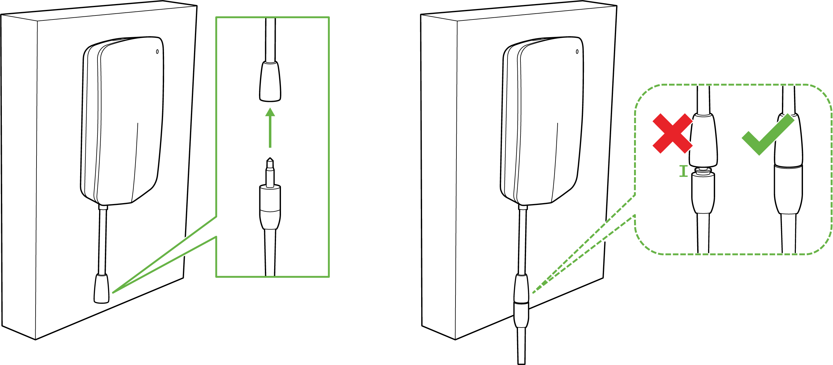
Once the mounting plate is on the desired surface, slide the MT11 sensor onto the plate and use the included Torx screw to secure the sensor.
-
Plug-in the supported probe for the MT11 to receive sensor data.
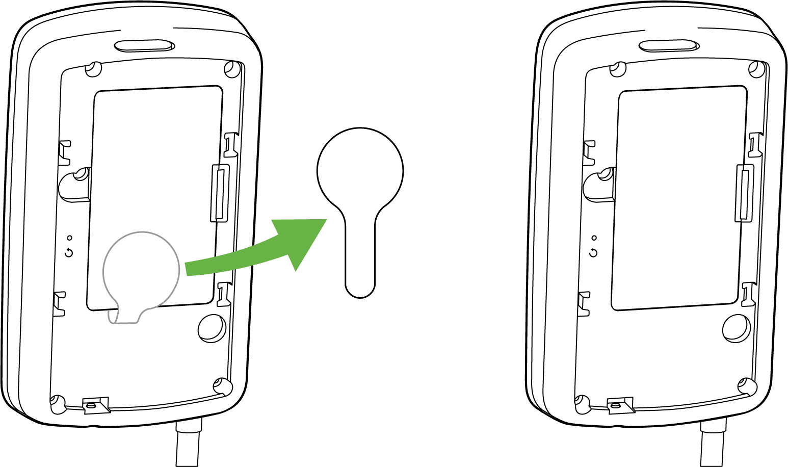
MT11 Probes Installation
Routing the probe cable through the hermetic seal
One of the easiest ways to set up monitoring in a cooler or a refrigerator is to route the probe cable through the hermetic seal. Follow the instructions below or simply refer to the video
Identify the location
Start by identifying the location of the install.
-
Make a note of the location where the sensor element will be installed and check how the cable can be routed.
-
Also make a note of any obstructions that may prevent or displace the cable.
Apply the rubber seal
-
Once the location is decided, apply the included rubber gasket on the refrigerator body where the hermetic seal is making contact with the body.
-
Route the probe cable through the center of the rubber seal and install the sensor element at the desired location.
Secure the cable
-
After the probe cable is situated at the desired location, secure the remaining length of the cable outside the refrigerator using the cable clips included in the packaging for the Probes to avoid any slack.
-
Optionally, you can use a piece of duct tape over the rubber seal to prevent displacing the cable.
Mount the MT11 body
As a final step, mount the MT11 body by referring to the instructions above. Make sure that when mounting MT11, it is within range of a qualified gateway.
The rubber seal gasket and sticky cable pads are included in the Probes packaging.
Drilling through the insulation of the refrigerator
In this method, we’ll be drilling a hole through the insulation of the refrigerator so the probe can be passed through while keeping the MT11 body outside within the operating range.
Drilling through a refrigerator may void your warranty. Please consult with your refrigerator manufacturer before making any physical modifications.
Pre-install Preparations
-
Specification - The diameter of the hole should be at least 15mm wide in order to successfully pass the probe.
-
Tools Required - This list will vary according to the type of material being used
-
Drill
-
Drill bits - pilot hole bit, boring hole bit
-
Sealant or a Caulk
-
Caulk gun
-
-
Identify the location -
-
Start by identifying the location of the install.
-
Make a note of the location where the sensor element will be installed and check how the cable can be routed.
-
Also make a note of any obstructions that may prevent or displace the cable.
-
Drilling
-
In our demonstration, we used a pilot drill bit to start the initial hole and made sure we went through the side of the refrigerator. This is an optional step if you have the appropriate drill bit for a 15mm wide hole.
-
Once the pilot hole was made, we used a wider drill bit to make the hole at least 15 mm wide for the probe to pass through.
Installing the Probe
- After the appropriate hole is drilled, clean up the debris and use some sandpaper to smoothen the surface.
- Route the probe cable through the hole.
- Secure the sensor element at the intended location to prevent it from being displaced.
Mounting the MT11 body
- Once the probe is installed, take the excess cable and secure it using the sticky cable pads on the outside of the refrigerator.
- Plug in the 3.5 mm jack on the MT11 pigtail and mount the body using the appropriate mounting method.
Support and Additional Information
If issues are encountered with device installation or additional help is required, contact Meraki Support by logging in to dashboard.meraki.com and opening a case by visiting the Get Help section.
Refer to the MT Frequently Asked Questions document for further queries on the MT sensors.
For additional information on Meraki hardware and other installation guides, please refer to documentation.meraki.com.