Meraki Auto VPN Configuration Settings
Click 日本語 for Japanese
Overview
Meraki Auto VPN is a feature on Cisco Secure Routers, MX and Z-series WAN appliances that enables site-to-site VPN connectivity between networks. It allows administrators to configure VPN settings through the Meraki dashboard, where tunnels between devices are automatically established and maintained. Auto VPN performs the work normally required for manual VPN configurations with a simple cloud based process.
When enabled through the dashboard, each participating MX and Z Series appliances automatically does the following:
- Advertises its local subnets that are participating in the VPN.
- Advertises its WAN IP addresses on Internet 1 and Internet 2 ports.
- Downloads the global VPN route table from the dashboard (automatically generated by the dashboard, based on each MXs advertised WAN IP/local subnet in the VPN network).
- Downloads the preshared key for establishing the VPN tunnel and traffic encryption.
The net result is an automatic mesh site-to-site VPN solution that is configured with a single click.
This article outlines how the Auto VPN mechanisms work and how Meraki manages the cloud processes for Auto VPN.
Definitions
-
VPN Registry: This is the main server mechanism that allows Auto VPN to happen. It is a cloud service that is used to keep track of the contact information for all the WAN Appliance participating in Auto VPN for an organization.
WAN Appliances in warm spare with Virtual IP address (VIP) will use VIP to communicate with the VPN registry.
-
Hub: Hubs are devices in a VPN topology that service connectivity from a remote peer site (such as a spoke) to the hub and the hub to the remote peer site. Hubs also act as a gateway for remote peer sites to communicate with each other via the hub.
-
Spoke: Remote sites that connect to a central hub and communicate with each other only through the hub.
-
Peer: This refers to another WAN Appliance within the same organization that a local WAN Appliance will form or has formed a VPN tunnel to.
-
Contact: This is the public IP and the UDP port that the WAN Appliance will communicate on for Auto VPN.
Auto VPN: A Component of Meraki SD-WAN
| SD-WAN Characteristics | Meraki SD-WAN Component |
|---|---|
| Support for VPNs | Meraki Auto VPN |
| Multiple connection types (MPLS, Internet, LTE, etc.) | WAN Appliance uplink options allow for multiple connection type. |
| Dynamic path selection (allows for load sharing across WAN connection) | WAN Appliances can perform uplink load balancing across WAN connections |
| Simple WAN Configurations Interface (Must support zero-touch provisioning at a branch, should be easy to set up) | Meraki dashboard & API configuration interfaces |
Auto VPN, as a component of SD-WAN, transitions the manual steps for setting the VPN tunnel into a simple automated process. It takes only a few clicks and makes it easy to deploy and manage an SD-WAN environment. It gives resilience, security and application optimization. It has automatic VPN route generation using the IKE/IPSec-like tunnels and all this is done in the Meraki cloud.
If you have two uplinks on your WAN Appliance, Auto VPN as a component of SD-WAN allows you to decide the flow preferences within the VPN tunnel under Security & SD-WAN > Configure > SD-WAN & traffic shaping page > Uplink selection > Multi-Uplink Auto VPN. Multi-Uplink Auto VPN allows you to create a VPN tunnel with flow preferences over both the uplinks.
If Multi-Uplink Auto VPN is disabled, the tunnel will be formed over the primary WAN link and will failover to the secondary if the primary fails.
Learn more with these free online training courses on the Networking Learning Hub:
Prerequisites and limitations
Licensing requirements
-
Cisco Secure Routers, MX and Z-series devices use a per-device licensing model, where each device requires a corresponding license in the Meraki dashboard
-
There are three license tiers such as Enterprise, Advanced Security, and Secure SD-WAN Plus
-
Auto VPN functionality is included as part of the MX and Z-Series feature set and does not require a separate license
-
Auto VPN can operate between MX and Z-Series Teleworker with supported license configurations, depending on the organization’s licensing model
Hardware requirements
-
All MX and Z-Series models support Auto VPN
Limitations
-
Auto VPN requires connectivity to the Meraki cloud to establish and maintain VPN tunnels
-
Upstream firewalls must allow outbound UDP ports 9350–9381 for Auto VPN registry communication
-
Network conditions such as restrictive NAT or firewall policies may prevent VPN tunnels from forming. In such situations, a manual upstream port forward to the MX may be required. Refer to NAT Traversal section down below.
Configuration steps
To enable Auto VPN between WAN appliances:
Step 1: Select the network containing the device you want to include in the VPN topology
Step 2: Setting up Auto VPN
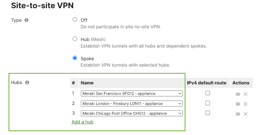
Navigate to Security & SD-WAN > Configure > Site-to-site VPN and select the Type (Hub or Spoke) to enable VPN connectivity. Auto VPN takes care of all connection settings and brokers the connections immediately.
Type
There are three options for configuring MX and Z-series devices in the Auto VPN topology:
- Off: The MX and Z-series devices does not participate in Site-to-Site VPN
- Hub (Mesh): The MX and Z-series devices establishes VPN tunnels to all remote Meraki VPN peers configured in Hub (Mesh) mode. The device also establish VPN tunnels to other MX and Z-series appliances in hub-and-spoke mode, where the other MX and Z-series device configured as a hub.
- Spoke: The MX device establishes VPN tunnels only to the specified hub devices. Other spokes are reachable through their respective hubs unless restricted by site-to-site firewall rules. If the majority of WAN Appliances in the Auto VPN domain are configured as Spoke with only a few key locations (such as data centers or headquarters) configured as hubs, then the Auto VPN environment has a hub-and-spoke topology.
Hub type
Exit hubs
This option is available only when the MX appliance is configured as a Hub.
It designates a remote MX device to receive all network traffic from the local MX. This creates a full tunnel configuration, where all traffic destined for the default route is sent to the specified MX.
Security features over full-tunnel VPN
In a full tunnel topology, all security and content filtering must be performed on the full tunnel client. The Exit hub will not apply content filtering, Intrusion Prevention System (IPS) blocking, or malware scanning to traffic coming in over the VPN. However, an Intrusion Detection System (IDS) scanning will be performed for this traffic.

Spoke type
Hubs
When an WAN appliance is configured as a spoke, multiple VPN hubs can be configured for that appliance. In this configuration, the spoke MX and Z-series device will send all site-to-site traffic to its configured VPN hubs.

Default route
When configuring hubs for a spoke, there is an option to select a hub as a Default route.
When enabled, the selected hub acts as the default route (0.0.0.0/0) for the spoke. Any traffic not destined for the following is sent to the default route:
-
Configured VPN peer networks
-
Static routes
-
Local networks
This routing applies to traffic originating from:
-
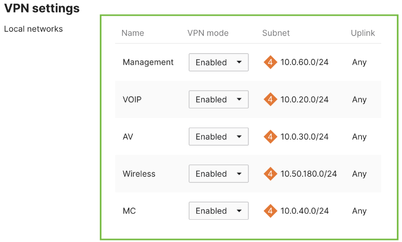
Subnets set to “In VPN”
-
Subnets with VPN mode “Enabled”
Subnets with VPN mode “Disabled” do not follow the VPN routing table.
Multiple hubs can be selected as default routes. These hubs are prioritized in descending order, with the highest priority at the top.

Configuring multiple VPN hubs
To add additional hubs, select the Add a hub button below the existing hub.
Only appliances in Mesh VPN mode can be configured as hubs. The number of Mesh VPN appliances in your dashboard organization determines the maximum number of hubs that can be configured.
The order in which hubs are configured defines the hub priority. Hub priority determines which hub is used when more than one VPN hub advertises the same subnet. The highest priority hub that meets the following criteria is used:
-
Advertises the subnet
-
Currently reachable via VPN
You can manage hubs as follows:
-
Delete a hub: Click the grey X next to the hub under the Actions column
-
Reorder hubs: Drag and drop the grey four-point arrow icon to change priority
Tunneling
There are two tunneling modes available for MX and Z devices configured as a Spoke:
-
Split tunnel (no default route): By default all WAN Appliances in the Auto VPN domain (dashboard organization) will only send traffic to an Auto VPN peer if the traffic is destined for a subnet contained within the Auto VPN domain. This is often referred to as 'split-tunnelling,' meaning that VPN-subnet-bound traffic is sent over VPN, and other traffic is routed normally via the primary WAN Appliance WAN uplink. If an organization wants to route all traffic (including traffic not contained within the Auto VPN domain) through a specific hub site, this is referred to as 'full-tunneling.' Full-tunneling only affects client data and all Meraki management traffic will egress directly via the primary WAN regardless.
To configure full-tunneling in a full mesh topology simply define an Exit hub from the WAN Appliances in the Auto VPN domain.

Send only site-to-site traffic, meaning that if a subnet is at a remote site, the traffic destined for that subnet is sent over the VPN. However, if traffic is destined for a network that is not in the VPN mesh (for example, traffic going to a public web service such as www.google.com), the traffic is not sent over the VPN. Instead, this traffic is routed using another available route, most commonly being sent directly to the Internet from the local MX and Z-series device. Split tunneling allows for the configuration of multiple hubs.
- Full tunnel (default route): To configure full-tunneling in a hub-and-spoke topology, simply associate a ‘Default route’ with one or more hub WAN Appliances.
The configured Exit hub(s) advertise a default route over Auto VPN to the spoke MX and Z series device. Traffic destined for subnets that are not reachable through other routes will be sent over VPN to the Exit hub(s). Exit hubs' default routes will be prioritized in descending order.
Full tunneling only affects client data, and Meraki management traffic will continue to use the WAN uplink directly.
Concentrator priority
The concentrator priority determines how appliances in Hub (Mesh) mode will reach subnets that are advertised from more than one Meraki VPN peer. Similarly to hub priorities, the uppermost concentrator in the list that meets the following criteria will be used for such a subnet.
A) Advertises the subnet
B) Currently reachable via VPN
It is important to note that concentrator priorities are used only by appliances in Mesh mode. An appliance in hub-and-spoke mode will ignore the concentrator priorities and will use its hub priorities instead.
NAT traversal
If the MX and Z-series device is behind a firewall or other Network Address Translation (NAT) device, there are two options for establishing the VPN tunnel:
-
Automatic: In most cases, the MX and Z-series device can automatically establish site-to-site VPN connectivity to remote Meraki VPN peers even through a firewall or NAT device using a technique known as "UDP hole punching". This is the recommended (and default) option.
-
Manual: Port forwarding: If the Automatic option does not work, you can use this option. When Manual: Port forwarding is enabled, Meraki VPN peers contact the MX and Z-series device using the specified public IP address and UDP port number. You will need to configure the upstream firewall to forward all incoming traffic on that UDP port to the IP address of the MX and Z-series device.