
Extending the LAN with a Wireless Mesh Link
Cisco Meraki MR access points (APs) can operate as mesh repeaters, which allows them to extend the wireless network range off of a limited number of gateway APs. Since repeaters also support wired clients plugged into their wired interface, a repeater can be used to bridge a remote LAN segment back to the main network.
Wireless Mesh repeaters can back-haul to access points acting as wireless gateways and:
- Utilize the same radio as used for mesh to serve wireless clients
- Utilize non-meshing radios to serve wireless clients
- Utilize wired uplink for use cases described below
This article explains how the LAN can be extended via a wireless bridge, including limitations and requirements. There are three supported designs for extending the LAN via wireless mesh.
- Extending the LAN for wired clients
- Extending the LAN for a mixture of wireless access points and wired clients
- Extending the LAN and configuring network segmentation
Note: Synchronization between a gateway MR and repeater MR takes several minutes in most scenarios. Additionally, it is recommended to upgrade the firmware and allow the devices to download their configuration prior to deployment.
Warning: As a general wireless networking rule, each wireless hop in a mesh network reduces the throughput of the link in half. As a result, wireless mesh networking may not be the most viable solution for environments that are required to support high-bandwidth or latency-intolerant applications. Meraki recommends limiting the amount of wireless hops to one (1) unless more are absolutely necessary to serve additional wireless clients.
Multicast protocols, including CDP, LLDP, VTP, etc., are not supported over a wireless mesh link.
Extending the LAN for Wired Clients
Administrators may utilize mesh repeaters to serve remote wired clients.
Configuration
In order for repeater APs to share their wireless connection over their Ethernet port, the following requirements must be met:
- At least one bridge-mode SSID must be configured in dashboard (can be an existing SSID used by clients, but must be in bridge mode).
- Both bridge APs must be configured to broadcast this SSID.
- If an SSID is in use that uses a VLAN ID, the switch port configuration connecting the gateway MR must be configured to allow this traffic. This can be done via the Allowed VLANs configuration within the switch port configuration. For additional information regarding switch port configuration, please see our MS Port Configuration Guide.
- VLANs must be pruned to only include those that are required on the remote side of the bridge.
For more information about bridge mode and how to configure a bridge SSID, please refer to our documentation regarding Wireless Client IP Assignment.
By default, a client or device plugged into the Ethernet port of a repeater will gain no network connectivity. Once a bridge SSID has been configured, navigate to Network-wide > Configure > General > Device configuration, find the option to configure Clients wired directly to Meraki APs, and set that option to have clients behave like they are connected to the bridge SSID (as shown below).

Please note the following:
- The authentication type of the SSID does not matter, wired clients will bypass authentication and gain network connectivity as though they had associated to that SSID.
- It is recommended to use a dedicated bridge-mode SSID that is configured to use device tags for per-AP availability in order to limit the SSID to only the intended APs.
- Wireless networking is highly susceptible to RF interference. Channel changes will result in a disruption of the link. If the RF environment is noisy, it may be best to disable DFS channels and limit the amount of channels available via an RF profile.
- Mesh repeaters do not support 802.11r (Fast BSS Transition).
Access points intended to form a wireless link or mesh together must be within direct line of sight of each other.
Wireless bridges running version 27.X or below only support a single VLAN. If support for multiple subnets is a requirement for the deployment, a layer 3-capable device will be required. MR repeaters will only send/receive untagged traffic on its wired interface regardless of the configuration of the SSID in use.
Starting 28.1, Multi-vlan support was added.
By extension, wired clients across the mesh link do not support the use of VLANs applied by Group Policies.
Warning: Link aggregation on dual-port APs (e.g., MR52, MR53, MR53E, MR57, MR84) must be disabled to allow wired clients connected directly to the AP to gain network connectivity and pass traffic through the wired port on the AP.
For example, if a repeater AP has a wired client connected to its Ethernet port, this AP will only be able to pass the client’s traffic if the link aggregation is disabled.
Example Topology
It is possible to extend the LAN segment off of the repeater, thus creating a larger "remote side" network. In most scenarios, a layer 2 switch will suffice. The below configuration shows the extension of the LAN using a SSID configured to use VLAN 20.
Only a single untagged VLAN is supported for the repeater side link. This will be the same VLAN the bridge-mode SSID is operating in.

Extending the LAN and Configuring Network Segmentation
It is possible to extend the LAN and support multiple subnets on the remote side of the bridge. However, this does require a layer 3 switch due to the nature of 802.11 frames preventing multiple VLAN IDs from traversing the wireless bridge link. The layer 3 switch will rewrite the frame and place it in the required (transit) VLAN when sending it to the wireless bridge (repeater MR)
Configuration
- Configure a bridge-mode SSID as noted in the topologies above.
- Configure layer 3 interfaces on the switch located on the remote side of the bridge.
- A transit VLAN (ie. VLAN 20 in diagram)
- Any additional access VLANs for APs and clients
- Configure the required static routes both upstream and on the remote side of the bridge.
- Configure the uplink/transit link for the switch. Only a single untagged VLAN is supported for this link. This will be the same VLAN the bridge-mode SSID is operating in.
- Configure the access ports for clients according to the layer 3 interfaces that have been created.
- Be sure to prune any VLANs that are not in use.
Example Topology
.png?revision=1)
Additional MRs and clients MUST be in a different broadcast domain than the transit link VLAN (ie. VLAN 20 in diagram) otherwise remote devices, including the MS, may lose uplink connectivity.
The wireless bridge and the additional MR that has been deployed at the remote side must not share any of the same channels. This can be achieved via configuring a static channel or by using RF profiles to prevent auto-channel selection of an overlapping channel.
An additional subnet can be configured in order to deploy additional MRs on the remote side of the bridge. This subnet must be unique and DHCP must be provided on the remote side of the bridge.
Multi-Hop Meshing
It is possible to form a multi-hop mesh relying on existing repeaters to relay the traffic from repeaters that cannot form a mesh to a gateway AP or send data over a wired link. The below scenario describes a multi-hop mesh where the furthest AP is two hops from a gateway.
Configuration
- Configure deployment as noted in "Extending the LAN and Configuring Network Segmentation" above.
- Configure additional SSID on MRs that will participate in multi-hop mesh.
- This SSID cannot be broadcast on the MRs forming the wireless bridge connection.
- Physically deploy the MRs.
- MRs must be in line of sight of their intended mesh neighbor.
- Repeater/mesh MRs should not be connected to the LAN that the gateway MR is connected to.
Example Topology
.png?revision=1)
Due to each hop reducing available bandwidth in half, it is recommended to use a layer 3 device in order to support at least one gateway MR on the remote side of the wireless bridge as opposed to using either of the bridge APs as the gateway for the multi-hop mesh.
Access points that are intended to form a link via mesh should not be connected to any cloud managed switches, as the switch will not be able to reach beyond the gateway MR. Access points that are participating in a multi-hop mesh do not support wired clients. IP communication outside of the proprietary mesh traffic will be blocked by the MR repeater, thus remote IP access to switches will be lost. In order to mix IP and mesh extension, a router would need to be introduced as described above.
Multiple VLANs over Mesh
Meraki APs will allow traffic from multiple VLANs over mesh links. This feature can be enabled by contacting support. There are a couple of conditions that must be met to support this functionality:
1. Clients wired directly into Meraki access points needs to be enabled and configured for a specific SSID where multiple VLANs are used. This option is found on the Network Wide > Configure > General page.

2. SSID configuration has to use Bridge mode. This option is found on the Wireless > Configure > Access Control page, Client IP assignment section.

Multi-VLAN support over Mesh is supported with MR 28.1 and higher firmware versions.
If you plan to have one or more Meraki access points behind a repeater access point, a layer 3 device needs to separate them as stated in Extending the LAN with a Wireless Mesh Link.
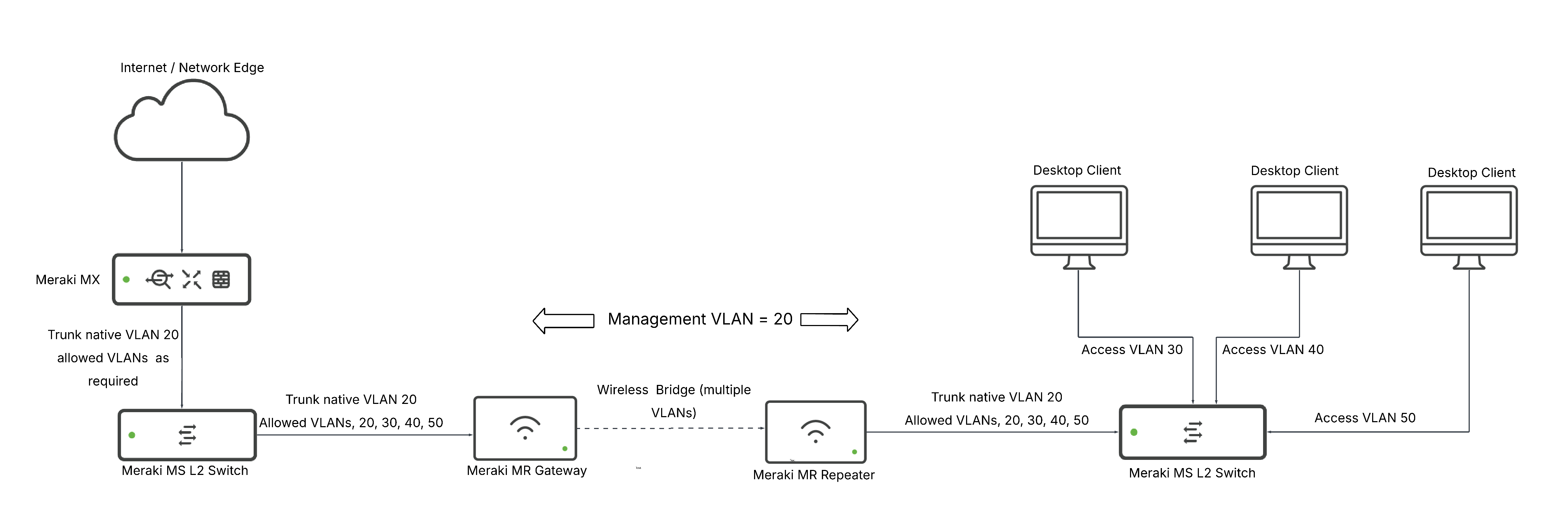
Extending the LAN with Segmentation for wired clients only
Example Topology
With the above feature enabled, it is possible to extend multiple VLANs over the wireless bridge, including DHCP traffic, so that a L2 switch will suffice to allow VLAN segmentation on the remote side for wired clients. This configuration uses a single management VLAN (20) for the switches and Gateway AP, and assumes that a bridge-mode SSID has been configured, as noted in the topologies above:
Extending the LAN with Segmentation for Wired and Wireless clients
This configuration is similar to 'Extending the LAN and Configuring Network Segmentation,' but with one key difference: we extend the management VLAN over the wireless bridge as a trunk, alongside the transit VLAN. This keeps management and internet traffic separate on the L3 switch, following best practice.
Configuration
- Configure a bridge mode SSID, as discussed here
- On the gateway L2 switch, configure a trunk link with the management VLAN as the Native VLAN (20 in this example), and prune so that the native and Transit VLAN (10 in this example) are allowed.
- On the L3 switch, the trunk link between the switch and the repeater should have the same configuration. The L3 switch should receive a management IP in VLAN 20.
- Configure layer 3 interfaces with DHCP servers on the switch located on the remote side of the bridge with:
- A transit VLAN (10 in this example).
- Any additional access VLANs for wired clients.
- A Management VLAN for APs (50 in this example).
- A VLAN for wireless client traffic (60 in this example): the SSID should be tagged with this VLAN.
5. Configure the required static routes on both sides of the bridge.
6. Configure the access ports for clients, and trunk ports for APs, according to the layer 3 interfaces created above:
- Be sure to prune any VLANs that are not in use.
Example Topology

The wireless bridge and the additional MR that has been deployed at the remote side must not share any of the same channels. This can be achieved via configuring a static channel or by using RF profiles to prevent auto-channel selection of an overlapping channel.
BPDUs over Mesh
Wireless Access points will forward BPDUs across mesh links. Mesh links can be used as redundant links between locations, as thus, BPDUs will be forwarded out as to prevent a loop in the L2 network. The following topology can help to understand a scenario in which this is beneficial:

Unsupported Topologies
Wireless bridging and mesh networking have very strict topology requirements. Below are examples of unsupported topologies.
Unsupported Topology Example: Additional MR on Remote Side
Use of a layer 2 switch and connecting additional access points to the switch will result in unpredictable behavior in most cases. As a result, it is not supported. If additional access points are required, please see the two sections above and select the scenario that best fits the environment.

Unsupported Topology Example: Clients Connected to Multi-Hop Mesh
Repeater APs that are beyond more than one wireless hop cannot serve wired clients. Multi-hop mesh should only be deployed to serve additional wireless clients.
.png?revision=1)