
Catalyst 9300/X/L-M Series Installation Guide
About this Guide
This guide provides instruction on how to install and configure your Catalyst 9300/X/L-M series switches in the Meraki-managed mode.
Product Overview
Models
|
Model number
|
Description
|
Uplink Configuration | Default AC Power Supply |
|---|---|---|---|
| C9300-24T-M |
24 port Gbe Data Only |
Modular Uplinks | 350W AC |
| C9300-24P-M |
24 port Gbe Data with 30W PoE+ |
Modular Uplinks | 715W AC |
| C9300-24U-M |
24 port Gbe Data with 60W UPOE |
Modular Uplinks | 1100W AC |
| C9300-24UX-M |
24 port mGig Data with 60W UPOE |
Modular Uplinks | 1100W AC |
| C9300-48T-M |
48 port Gbe Data Only |
Modular Uplinks | 350W AC |
| C9300-48P-M |
48 port Gbe Data with 30W PoE+ |
Modular Uplinks | 715W AC |
| C9300-48U-M |
48 port Gbe Data with 60W UPOE |
Modular Uplinks | 1100W AC |
| C9300-48UXM-M |
48 port Cisco UPOE, 36 ports 100M/1G/2.5G + 12 ports Multigigabit (10G/5G/2.5G/1G/100M) |
Modular Uplinks | 1100W AC |
| C9300-48UN-M | 48 port 5Gbps Multigigabit UPOE ports (5G/2.5G/1G/100M) | Modular Uplinks | 1100W AC |
| C9300-24S-M | 24 port 1Gbe SFP | Modular Uplinks | 715W AC |
| C9300-48S-M | 48 port 1Gbe SFP | Modular Uplinks | 715W AC |
| C9300X-12Y-M | 12 port 25G/10G/1G SFP28 | Modular Uplinks | 715W AC |
| C9300X-24Y-M | 24 port 25G/10G/1G SFP28 | Modular Uplinks | 715W AC |
| C9300X-48TX-M | 48 port Data, 48x 10G Multigigabit (10G/5G/2.5G/1G/100M) | Modular Uplinks | 715W AC |
| C9300X-24HX-M | 24 port Cisco UPOE+, 24x 10G Multigigabit (10G/5G/2.5G/1G/100M) |
Modular Uplinks | 1100W AC |
| C9300X-48HX-M | 48 port Cisco UPOE+, 48x 10G Multigigabit (10G/5G/2.5G/1G/100M) with 90W UPOE+ |
Modular Uplinks | 1100W AC |
| C9300X-48HXN-M | 48 port Cisco UPOE+, 8x 10G Multigigabit (10G/5G/2.5G/1G/100M) + 40x 5G Multigigabit (5G/2.5G/1G/100M) | Modular Uplinks | 1100W AC |
| C9300L-24T-4X-M | 24 port Data Only |
Fixed Uplinks |
350W AC |
| C9300L-48T-4X-M | 48 port Data Only | Fixed Uplinks 4x 10G/1G |
350W AC |
| C9300L-24P-4X-M | 24 port Data with 30W PoE+ | Fixed Uplinks 4x 10G/1G |
715W AC |
| C9300L-48P-4X-M | 48 port Data with 30W PoE+ | Fixed Uplinks 4x 10G/1G |
715W AC |
| C9300L-48PF-4X-M | 48 port Data with 30W PoE+ (Full Power) | Fixed Uplinks 4x 10G/1G |
1100W AC |
| C9300L-24UXG-4X-M | 24 port Cisco UPOE, 8 ports Multigigabit (10G/5G/2.5G/1G/100M) + 16 ports 1G (1G/100M/10M) | Fixed Uplinks 4x 10G/1G |
1100W AC |
| C9300L-48UXG-4X-M | 48 port Cisco UPOE, 12 ports Multigigabit (10G/5G/2.5G/1G/100M) + 36 port 1G (1G/100M/10) |
Fixed Uplinks 4x 10G/1G |
1100W AC |
Note: For Japan, the recommendation is to deploy the switch with 200V+ outlets. The 1100/1900W power supplies will not operate on 100V. Please reference Table 13. AC Power Cords for the appropriate 250VAC power cable.
Technical Specifications
-
Each model has 1 dedicated management interface (local status page access)
-
The 9300 model has two stack ports supporting (480G), the 9300X supports 1Tbps stacking and is backward compatible with 9300.
-
The 9300 and 9300X can stack together at 480G. The 9300L can only stack with other 9300L switches.
-
The 9300 and 9300X modular uplinks are model specific (modules are not interchangeable between the 9300 and 9300X)
-
Operating temperature for each of the model: -5°C to 45°C
-
Storage and Transportation Temperature: -20°C - 70°C
-
Humidity: 5 to 90%
| Model | Interfaces |
PoE/ UPoE Capabilities |
Power Load (idle/max) | Available PoE | Hot Swap Power Supply |
| C9300-24T-M | 24 x 1GbE RJ45 | n/a | 79.2 / 99 W | - | Yes, Dual |
| C9300-24P-M | 24 x 1GbE RJ45 | PoE | 84.1 / 554.4 W | 445W | Yes, Dual |
| C9300-24U-M | 24 x 1GbE RJ45 | UPoE/802.3bt | 85.4 / 990.3 W | 830W | Yes, Dual |
| C9300-24UX-M | 24 x mGbE RJ45 | UPoE/802.3bt | 162.7 / 809.9 W | 560W | Yes, Dual |
| C9300-48T-M | 48 x 1GbE RJ45 | n/a | 83.9 / 109.9 W | - | Yes, Dual |
| C9300-48P-M | 48 x 1GbE RJ45 | PoE | 92.6 / 555 W | 437W | Yes, Dual |
| C9300-48U-M | 48 x 1GbE RJ45 | UPoE/802.3bt | 145 / 844.9 W | 822W | Yes, Dual |
| C9300-48UXM-M |
36 x 100M/1G/2.5G + 12 x 100M/1G/2.5G/5G/10G |
UPoE/802.3bt | 218.5 / 785.5 W | 490W | Yes, Dual |
| C9300-48UN-M | 48 x 100M/1G/2.5G/5G | UPoE/802.3bt | 157.9 / 843.8 W | 645W | Yes, Dual |
| C9300-24S-M | 24 x 1GbE SFP | n/a | 84.6 / 124.3 W | - | Yes, Dual |
| C9300-48S-M | 48 x 1 GbE SFP | n/a | 88.9 / 158.3 W | - | Yes, Dual |
| C9300X-12Y-M | 12 x 1/10/25 GbE SFP28 | n/a | 97.1 / 157.3 W | - | Yes, Dual |
| C9300X-24Y-M | 24 x 1/10/25 GbE SFP28 | n/a | 139.6 / 243.7 W | - | Yes, Dual |
| C9300X-48TX-M | 48 x 100M/1G/2.5G/5G/10G | n/a | 184.3 / 269.8 W | - | Yes, Dual |
| C9300X-24HX-M | 24 x 100M/1G/2.5G/5G/10G | UPoE+/802.3bt | 127.2 / 912.6 W | 735W | Yes, Dual |
| C9300X-48HX-M | 48 x 100M/1G/2.5G/5G/10G | UPoE+/802.3bt | 178.9 / 672 W | 590W | Yes, Dual |
| C9300X-48HXN-M |
8 x 100M/1G/2.5G/5G/10G 40 x 100M/1G/2.5G/5G |
UPoE+/802.3bt | 127.2 / 912.6 W | 690W | Yes, Dual |
| C9300L-24T-4X-M |
24 x 1GbE RJ45 4 x 1G/10G SFP+ Uplink |
n/a | 56.85 / 73.54 W | - | Yes, Dual |
| C9300L-48T-4X-M |
48 x 1GbE RJ45 4 x 1G/10G SFP+ Uplink |
n/a | 60.97 / 86.77 W | - | Yes, Dual |
| C9300L-24P-4X-M |
24 x 1GbE RJ45 4 x 1G/10G SFP+ Uplink |
PoE+/802.3bt | 63.70 / 607 W | 505W | Yes, Dual |
| C9300L-48P-4X-M |
48 x 1GbE RJ45 4 x 1G/10G SFP+ Uplink |
PoE+/802.3bt | 67.40 / 598 W | 505W | Yes, Dual |
| C9300L-48PF-4X-M |
48 x 1GbE RJ45 4 x 1G/10G SFP+ Uplink |
PoE+/802.3bt | 67.38 / 1023.56 W | 890W | Yes, Dual |
| C9300L-24UXG-4X-M |
8 x 100M/1G/2.5G/5G/10G mGig 16 x 1G (1G/100M/10M) GbE RJ45 4 x 1G/10G SFP+ Uplink |
UPoE/802.3bt | 68.98 / 1049.47 W | 880W | Yes, Dual |
| C9300L-48UXG-4X-M |
12 x 100M/1G/2.5G/5G/10G mGig 36 x 1G (1G/100M/10M) GbE RJ45 4 x 1G/10G SFP+ Uplink |
UPoE/802.3bt | 104.56 / 875.3 W | 675W | Yes, Dual |
Product View and Physical Features
A Cloud ID will be located on the top or bottom panel that starts with a Q, this will be the serial number used to claim the device into the dashboard.
Front Panel Components
Inactive components: The following front panel components are used only when the device is being managed by DNAC of via CLI, and remain inactive in the Meraki-managed mode
1. STAT, Duplex, Speed, Stack, PoE, XPS and Console LEDs.
2. USB Type-A storage and the USB Type-B console ports.
The XPS and S-PWR LEDs do not exist on the C9300L-M series switches.

|
Item |
Component |
Purpose |
|---|---|---|
|
1 |
Blue Beacon LED |
Reports systems status (along with the System LED) Please refer to the LED indicators in the Meraki-managed mode table for details |
| 2 | Reset (Mode) button |
Reset switch to factory settings. Please refer to the Factory Reset Process section for details |
|
3 |
System LED | Reports status of the Switch (along with the Blue Beacon LED) |
|
4 |
Active LED |
Identifies the switch's role in the stack (solid= active; blinking= standby; off= member is neither the active nor standby switch) |
| 5 | StackPower LED | Indicates StackPower operation states. |
LED Indicators in the Meraki-managed mode
|
|
System status |
Blue Beacon LED |
System LED |
|
1 |
Switch is powered off or not receiving power. |
Off |
Off |
|
2 |
Switch is powered on and is loading the bootstrap firmware. |
Solid amber |
|
|
3 |
Switch is loading the operating system. |
Blinking green |
|
|
4 |
System error: Switch failed to load operating system or bootstrap firmware. |
Blinking amber |
|
|
5 |
Setting up local management and cloud-connectivity requirements. |
Flashing Blue |
Cycling b/w green & amber (OR blinking green) |
|
6 |
System error: Switch failed to complete local provisioning. |
Solid amber |
|
|
7 |
Switch is completely provisioned but unable to connect to Meraki cloud. |
Solid Blue |
Solid amber |
|
8 |
Firmware download / upgrade in progress. |
Blinking green |
|
|
9 |
There is a fault with the power supply, fan, or network module (not traffic-related). |
Blinking amber |
|
|
10 |
Switch is fully operational and connected to the Meraki cloud. |
Solid green |
Back Panel Components
Inactive components: When operating in the Meraki-managed mode, the C9300 will disable the RJ45 console port.
 Factory Reset Button
To perform a factory reset, keep the mode button pressed for 21 seconds or more. Release the button when you see the LED lights stop flashing. The switch will reboot and revert to its original factory settings.
Safety and Warnings
These operations are to be taken with respect to all local laws. Please take the following into consideration for safe operation:
- Power off the unit before you begin. Read the installation instructions before connecting the system to the power source.
- Before you work on any equipment, be aware of the hazards involved with electrical circuitry and be familiar with standard practices for preventing accidents.
- Read the mounting instructions carefully before beginning installation. Failure to use the correct hardware or to follow the correct procedures could result in a hazardous situation to people and damage to the system.
- This product relies on the building’s installation for short-circuit (overcurrent) protection. Ensure that the protective device is rated not greater than: 15 A, 125 Vac, or 10A, 240 Vac.
- Please only power the device with the provided power cables to ensure regulatory compliance.
Package contents
In addition to the Catalyst 9300 series switch, each shipment includes the following.
- 1 x default power supply unit for the switch model (please refer to the power supply and specifications section)
- Rack mount brackets (rack screws not included)
- 3 x Pre-installed fans.
- STACKING NOTE: The C9300L does NOT include stacking ports by default. Please order the C9300L-STAK-KIT2-M with every C9300L switch that you plan to deploy in a stack. That kit includes two stacking ports and a 50cm stacking cable.
Catalyst 9300-M Deployment Best Practices
Before powering on devices or connecting an uplink port to the LAN, ensure to follow the steps outlined below or watch this short video.
The above video will link to a MS390 but the steps and information are the same for the C9300-M.
Configure your Dashboard Network
To add devices to your Meraki dashboard network please refer to the Creating a Dashboard Account and Organization document.
Check and Set Network Firmware
Ensure that the switch network is set to the correct firmware version. As of Feb 2024 CS16(GA) is the recommended version. Recommended versions are subject to change and are available in each dashboard by navigating to Organization > Firmware Upgrades
You can refer to Managing Firmware Upgrades for steps to set network firmware to the desired version.
Check and Configure Upstream Firewall Settings
If a firewall is in place, it must allow outgoing connections on particular ports to particular IP addresses. The most current list of outbound ports and IP addresses for your particular organization can be found under Help → Firewall info. The help button is located on the top right corner of any dashboard page. For more information refer to Upstream Firewall Rules for Cloud Connectivity.
Stacking
For stacking please refer to this section Stack Cabling Installation
Assigning an IP Address
All switches must be assigned routable IP addresses. These IP addresses can be dynamically assigned via DHCP or statically assigned. C9300 switches can support a total count of 1000 VLANs per stand-alone switch or switch stack. VLAN ID 1-1000 are configured by default, however, the active VLANs can be changed via the local status page or dashboard. When installing an C9300, it is important to ensure that any DHCP services or IP address assignments used for management fall within the active VLAN range.
Note: To utilize any VLANs outside of 1-1000 on a Catalyst Meraki C9300, the switch or switch stack must have ALL of its trunk interfaces set to an allowed vlan list that contains a total that is less than or equal to 1000 VLANs, including any of the module interfaces that are not in use. For example: If a switch needs to utilize VLANs 1,100-200,300-400,2100-2200,3000-3100, EVERY trunk interface on that switch must be configured with that allowed VLAN list or a subset of it.
Additionally, VLANs above 1000 cannot be added directly in the initial trunk allowed VLAN configuration. The configuration must be completed in two steps:
- First configure and save only the VLANs below 1000.
Example:
1,100-200,300-400 - After saving the configuration, edit the trunk allowed VLAN list again to add the VLANs above 1000.
Example:
2100-2200,3000-3100
The easiest method to do this is to perform the following:
- Navigate to Switch > Switch ports
- in the search bar use the following search term depending on if it is a stack or a single switch:
- switch:"{name of switch}" is:trunk
- stack:"{name of stack}" is:trunk
- Select all trunks configured with the allowed VLANs of 1-1000
- set to new list including new range of VLANs. (example: 1,100-200,300-400,2100-2200,3000-3100)
- Click Update

Note: For the C9300X/L series, if you receive an error a "Validation failed: This switch is limited to 1000 VLANs" error when adding switches to a network, please use the VLAN Database feature to configure the active VLANs on the network.
Dynamic Assignment
When using DHCP, the DHCP server should be configured to assign a static IP address for each MAC address belonging to a Meraki switch. Other features of the network, such as 802.1X authentication, may rely on the property that the switches have static IP addresses.
Please make sure that the DHCP server used for providing a management IP address to the switch has an available address pool that falls within the active VLAN range.
Static Assignment
Static IPs can be assigned using the local status page on each switch. For more information on how to configure static IP from the local status page refer to this documentation.
Static IP via DHCP Reservations
Instead of associating each Meraki switch individually to configure static IP addresses, an administrator can assign static IP addresses on the upstream DHCP server. Through “DHCP reservations,” IP addresses are “reserved” for the MAC addresses of the Meraki switches. Please consult the documentation for the DHCP server to configure DHCP reservations.
Check upstream VLAN configuration
Ensure the upstream switch/router port is configured properly and there is no VLAN mismatch.
Check STP configuration
Meraki-managed C9300 series switches run a single instance of MST out of the box. Please read MS Best Practices prior to deployment.
NOTE: If you plan to deploy Meraki switches into an existing Catalyst network running PVST/PVST+/Rapid-PVST, please refer to this document for interoperability. To migrate your existing Catalyst switches to MSTP, please see Configuring Spanning Tree on Meraki MS Switches for more information.
Boot-up Process and Firmware Upgrades
This section provides a detailed guide on what to expect during the boot-up and firmware upgrade process. The following image illustrates the various stages the switch will undergo during a firmware upgrade, which includes a system reboot. When a switch is powered-on, or rebooted from the Dashboard, it will only go through the stages of the System boot-up process.
The status of the Dashboard-connectivity and the local status page (LSP) availability in each of these stages are also covered in the illustration and the table below.
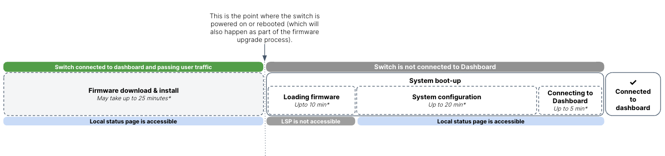
* The durations stated in the illustration above were measured using a 6-member stack of 48-port switches. The actual time required for system boot-up and configuration will also depend on the stack size, port density and any user-defined configuration.
The following table offers another view on what to expect from the Blue Beacon and System LED as the switch progresses through these stages. For an exhaustive list of system states, please refer to the section on LED Indicators in the Meraki-managed mode.
|
Stage |
System status |
Blue Beacon LED |
System |
Dashboard status |
Local Status Page (LSP) status |
|
Firmware download & installation |
Firmware download and upgrade in progress. |
Solid blue |
Blinking green |
Switch is connected to and managed by the Dashboard. |
LSP is accessible and can be used to manage the switch. |
|
System boot-up |
Switch is powered on and is loading the bootstrap firmware. |
OFF |
Solid amber |
Switch is not connected to Dashboard. |
LSP is not accessible |
|
System configuration |
Switch is loading the operating system. |
OFF |
Blinking green |
Switch is not connected to Dashboard. |
LSP is accessible and can be used to manage the switch. |
| Setting up local management IP and cloud-connectivity requirements. Note: If the switch has not been assigned a static management IP previously, it will try to obtain an IP via DHCP in this stage. |
Flashing blue | Cycling b/w green & amber (OR blinking green) | Switch is not connected to Dashboard. | LSP is accessible can be used to manage the switch. | |
|
Connecting to dashboard |
Switch is fully operational and connected to the Meraki cloud |
ON/Solid blue |
Solid green |
Switch is connected to Dashboard and operational. |
LSP page is accessible |
Device reboot/ reset precaution
Do not power down or reset the device during a firmware upgrade. Please refer to the table above or the section on LED Indicators in the Meraki-managed mode for details of the indicators for firmware upgrade.
Once the devices are upgraded to the latest version continue configuring other switch features/settings. For details refer to the MS documentation
Installation Instructions
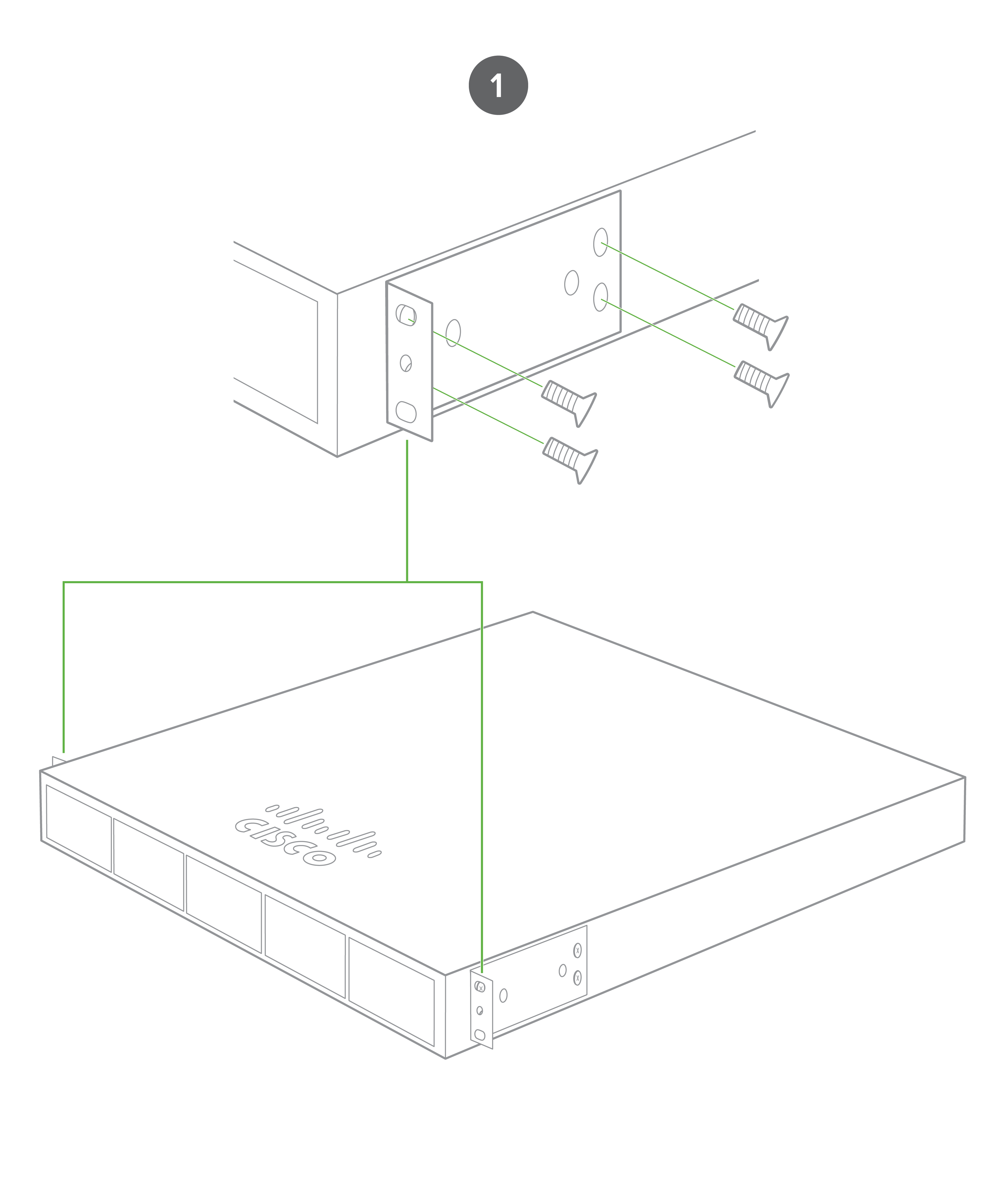
1. Attach the rack mount bracket to both sides of the switch as shown below:
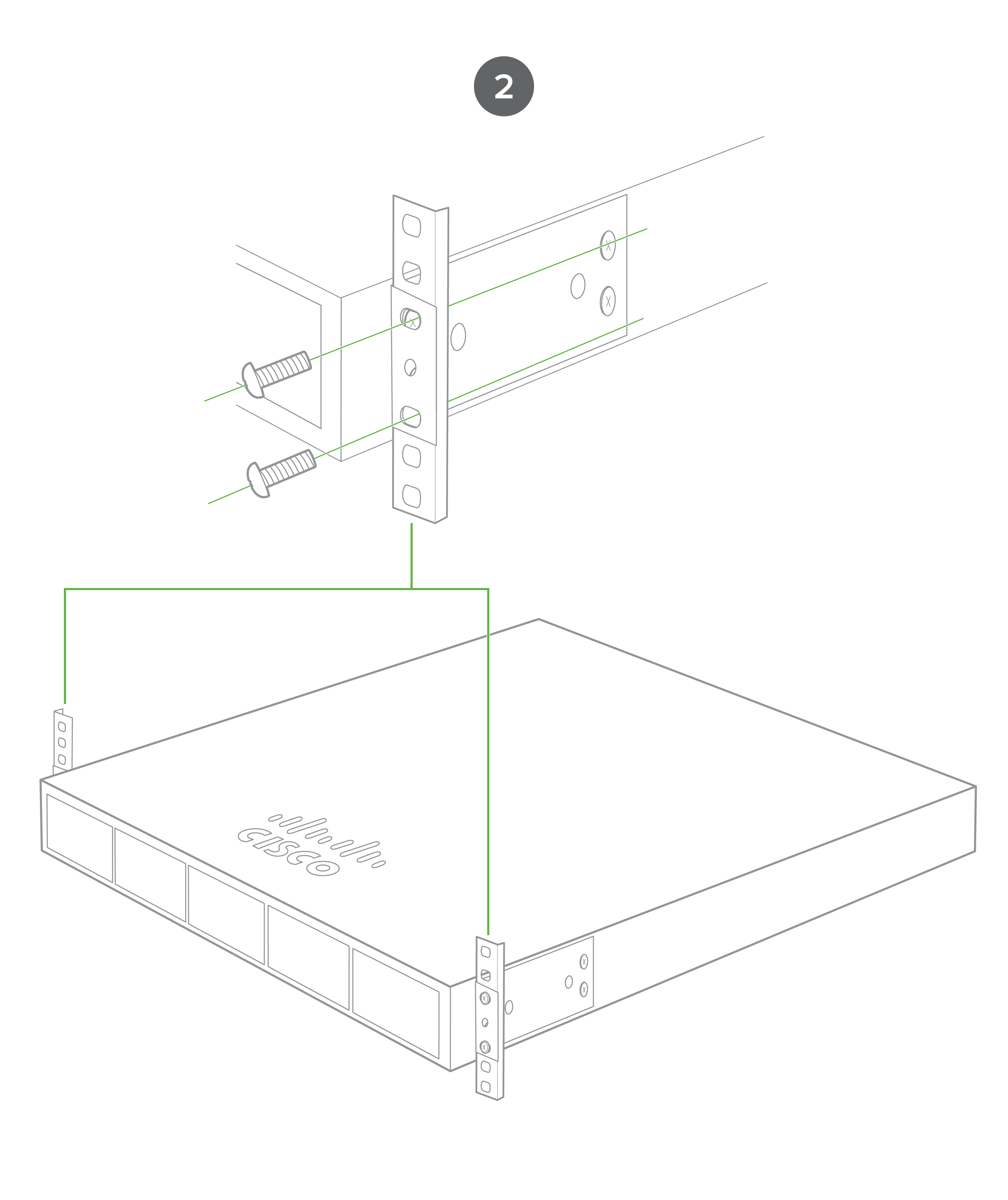
2. Align the rack mount brackets on the sides of the switch onto the rack.
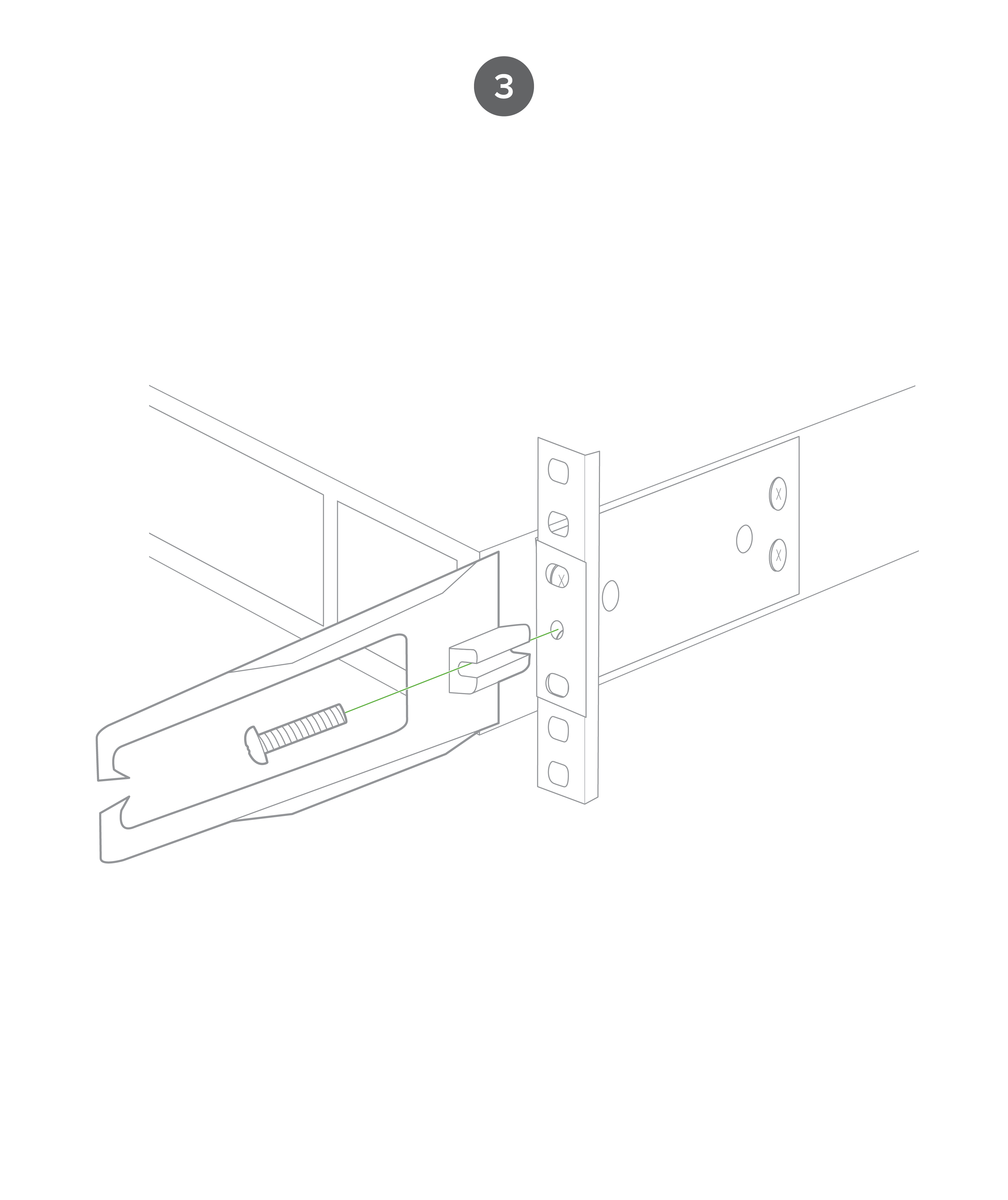
3. Secure and screw in the rack mount bracket on to the rack.
4. Insert the Uplink module.
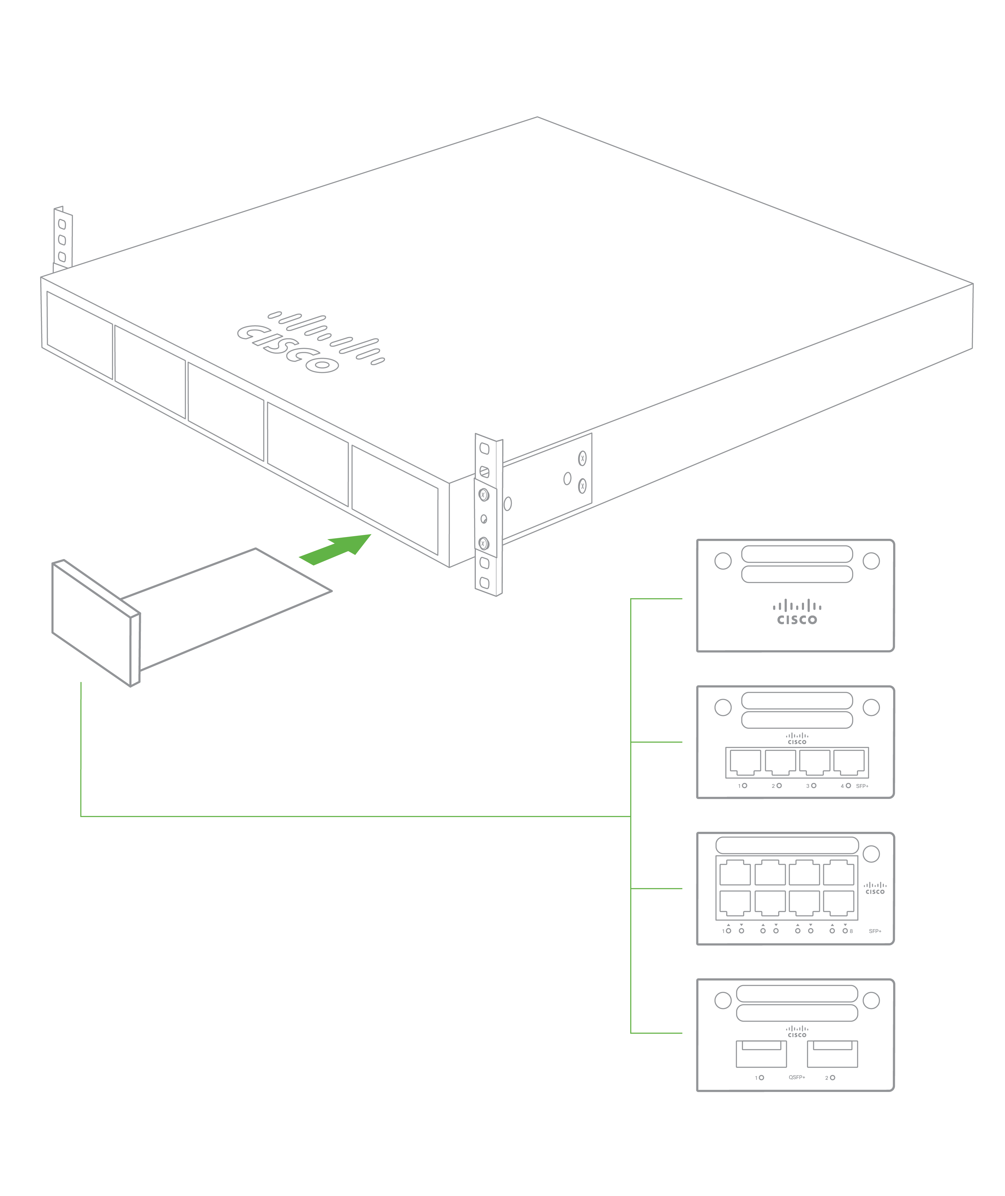
Note: The C9300/X uplink modules are hot-swappable and can be inserted/removed while powered.
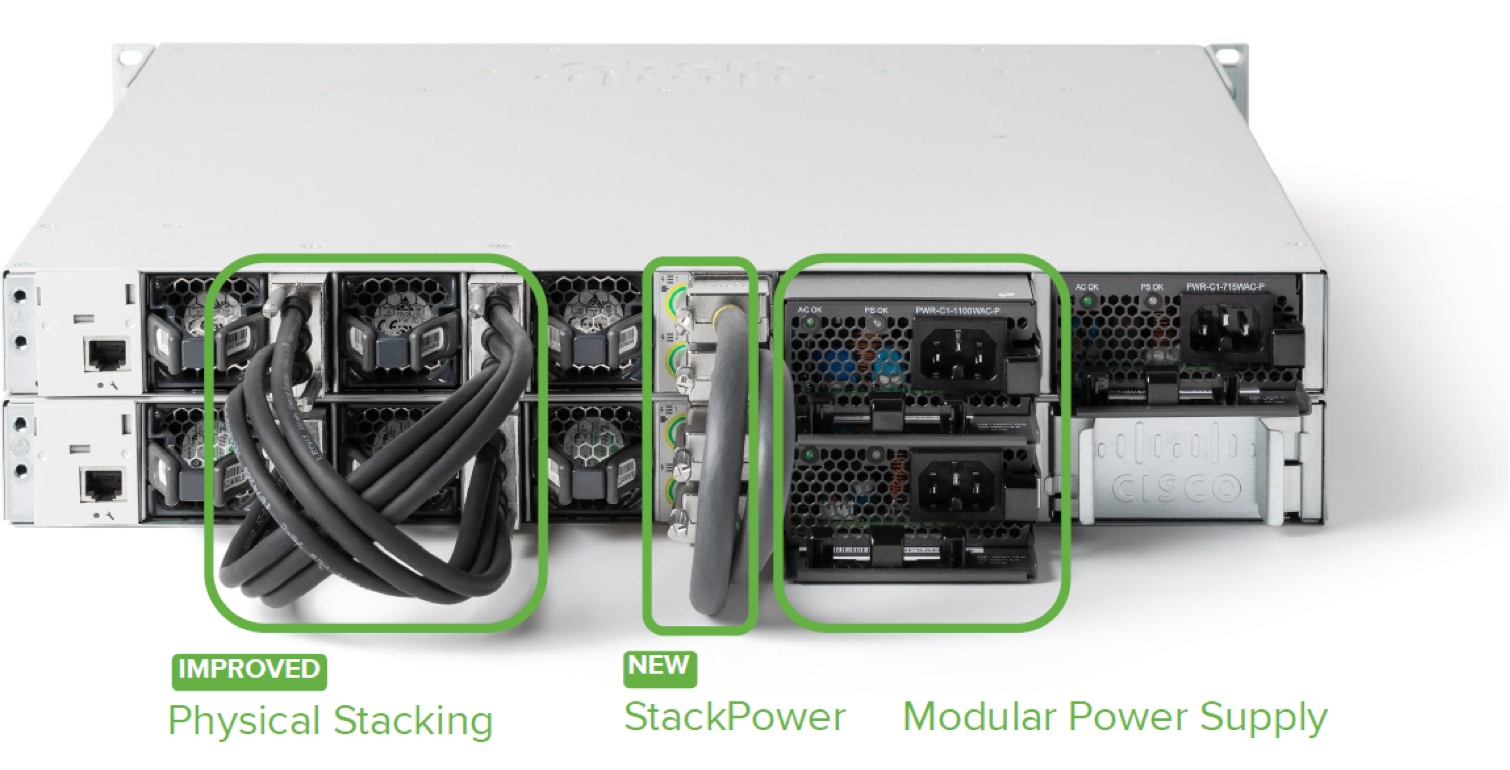
Stack Cabling Installation (9300/9300X)
- Connect the cable to the stack port on the switch back panel (as shown in the back panel diagram). Align the connector and connect the stack cable to the stack port on the switch back panel and finger-tighten the screws (clockwise direction). Make sure the Cisco logo is on the top side of the connector.
- Connect the other end of the cable to the port on the other switch and finger-tighten the screws. Avoid over tightening the screws.

Please refer to these instructions here before stacking C9300 out of the box.
Note: Stackwise Stacking cables are NOT hot-swappable.
Stack Cabling Installation (9300L)
- Install the StackWise adapter in each destination StackWise port, and secure it in place using the supplied Torx T15 key, or a Torx T15 screwdrive
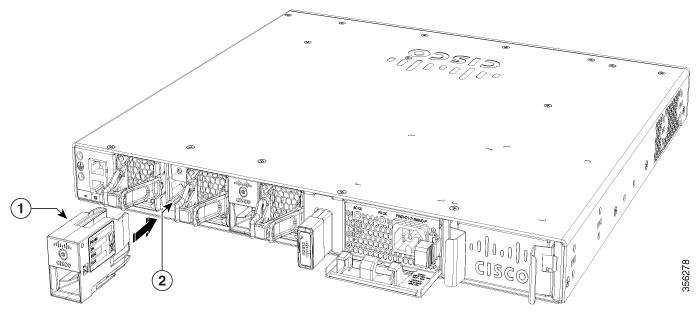
- Connect the cable to the stack port on the switch back panel (as shown in the back panel diagram). Align the connector and connect the stack cable to the stack port on the switch back panel, insert until the spring latch locks into the slot.
- Connect the other end of the cable to the port on the other switch, ensure the spring latch is locked in the slot.
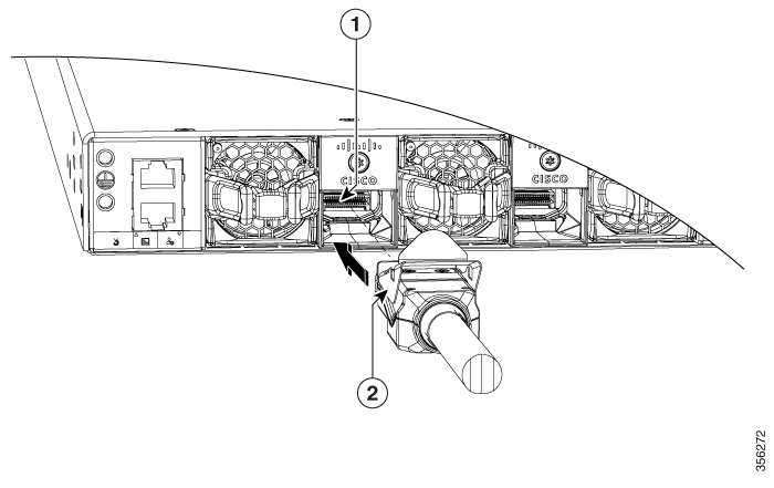
StackPower Cabling Installation
- StackPower on C9300 and C9300X switches supports a ring topology of up to 4 switches.
- Connect the end of the cable with a green band to either StackPower port on the first switch (see back panel diagram to locate the StackPower ports). Align the connector correctly, and insert it into a StackPower port on the switch rear panel.
- Connect the end of the cable with the yellow band to another switch. Hand-tighten the captive screws to secure the StackPower cable connectors in place.
- StackPower feature doesn't need any dashboard configuration but is automatically enabled when the cables are installed.
Basic Troubleshooting
The following steps can be used for troubleshooting basic connectivity issues with your switch.
- Soft Reset the switch by holding the factory reset button for 10-15 seconds (less than 20seconds)
- Factory Reset the switch by holding the factory reset button for > 21 seconds
- After a factory reset, the switch will re-download its firmware that can take a while on slow internet links. (Expect 1GB of firmware per switch/stack)
- Try switching cables, or testing your cable on another device
Reference https://documentation.meraki.com/MS for additional information and troubleshooting tips.
If you are still experiencing hardware issues, please contact Cisco Meraki support by logging in to dashboard and using the Help option near the top of the page, then opening and email case or calling using the contact information on that page.
Warranty
Switch warranty coverage periods are as follows:
| Time Period | Comments | |
| C9300 Series | Lifetime | Including 9300 / 9300X / 9300L models |
| Switch Accessories | 1 Year |
The following are considered accessories: SFP Modules, twinax/SFP+ cables, stacking cables, all mounting kits and stands, interface modules, additional power cords, PoE injectors |
Note: The above table is a general guideline for warranty terms and is not final. Warranty terms are subject to printed warranty information on the online Meraki Returns and Policy section.
If your Cisco Meraki device fails and the problem cannot be resolved by troubleshooting, contact support to address the issue. Once support determines that the device is in a failed state, they can process an RMA and send out a replacement device free of charge. In most circumstances, the RMA will include a pre-paid shipping label so the faulty equipment can be returned.
In order to initiate a hardware replacement for non-functioning hardware that is under warranty, you must have access to the original packaging the hardware was shipped in. The original hardware packaging includes device serial number/Cloud ID and order information, and may be required for return shipping.
Meraki C9300 devices have been tested and found to comply with the limits for a Class A digital device, pursuant to part 15 of the FCC rules. A digital device that is marketed for use in a residential environment notwithstanding use in commercial, business and industrial environments.
Additional warranty information can be found on: https://meraki.cisco.com/support#process:warranty
Support and Additional Information
If issues are encountered with device installation or additional help is required, contact Meraki Support by logging in to dashboard.meraki.com and opening a case by visiting the Get Help section.
- The equipment is intended for industrial or other commercial activities.
- The equipment is used in areas without exposure to harmful and dangerous production factors, unless otherwise specified in the operational documentation and/or on the equipment labeling.
- The equipment is not for domestic use. The equipment is intended for operation without the constant presence of maintenance personnel.
- The equipment is subject to installation and maintenance by specialists with the appropriate qualifications, sufficient specialized knowledge, and skills.
- Rules and conditions for the sale of equipment are determined by the terms of contracts concluded by Cisco or authorized Cisco partners with equipment buyers.
- Disposal of a technical device at the end of its service life should be carried out in accordance with the requirements of all state regulations and laws.
- Do not throw in the device with household waste. The technical equipment is subject to storage and disposal in accordance with the organization's disposal procedure.
- The equipment should be stored in its original packaging in a room protected from atmospheric precipitation. The permissible temperature and humidity ranges during storage are specified in the Operation (Installation) Manual.
- Transportation of equipment should be carried out in the original packaging in covered vehicles by any means of transport. The temperature and humidity during transportation must comply with the permissible established ranges of temperature and humidity during storage (in the off state) specified in the Operation Manual (Installation).
For additional information on Meraki hardware and for other installation guides, please refer to documentation.meraki.com.
Additionally, you may refer to Cisco Catalyst 9300 Series Switches Hardware Installation Guide.