
Designing Meraki MV Smart Camera Solutions
There are a number of ways to design an IP surveillance system. The most important part of the design is identifying areas of security concern and positioning cameras to cover those areas. There are a variety of ways to design camera coverage for the same building. Too many designs are primarily built with the cost of installation in mind, instead of looking at the system as an investment in protecting assets and/or people. A good IP surveillance system should be focused on protecting people and assets. The first steps to building such a system are analyzing the building or facility and conducting a site survey.
Site Survey
Conducting a site survey helps provide an understanding of the security needs of a building/facility, and determines the requirements to address those needs. At the conclusion of a site survey, there should be a clear understanding of what needs to be monitored, the materials/parts needed, labor required, total number and locations of cameras to be installed, and an estimated cost for deploying the solution.
Pre-site Survey Requirements
The list below is a starting point to identifying deployment needs, and will help ensure a better site survey outcome:
-
Acquire to-scale floor plans of the building(s)
-
A purpose of the site survey is to determine the mounting locations of cameras to be installed. Having floor plans helps the site administrator and the installer both fully understand the intent of the design and requirements. If outdoor camera coverage is also required, try to obtain external building plans as well.
-
-
Locate all network equipment closets
-
During the site survey it is necessary to understand existing network equipment, as the cameras will most likely be powered by and connected to the network. Identifying these locations beforehand is necessary.
-
-
Ask the simple questions:
-
Why is an IP video surveillance system needed?
-
What purpose does the system serve?
-
What are the requirements the system MUST have and why MUST the deployment have them?
-
When does the project need to be done?
-
Where is camera coverage required?
-
Who and/or what needs to be protected?
-
Are there any restrictions around mounting cameras to walls and/or ceilings?
-
Are there any restrictions around running CAT5e/6/7 cabling throughout the building/facility?
-
-
Get keys and access to ALL parts of the building/facility
-
This may be difficult as some companies/entities have high levels of security. Be sure to coordinate with management/security/facilities, and explain the purpose of and requirements for survey.
-
-
Schedule and treat the site survey like a project
-
Coordination and communication is key to making the site survey a success. Identifying things in the pre-site survey meeting can save a lot of time during the site survey.
-
-
Understand and know the County/State/Local regulations around cameras/surveillance for each facility to be surveyed
Conducting a Site Survey
The site survey determines where to place the cameras. It may also uncover additional suggestions or recommendations that were not initially considered.
Site Survey Checklist
-
Have a system to take extensive notes and make recommendations
-
Have several copies of the floor plans handy for marking where cameras should be installed
-
Take lots of pictures! Pictures can help convey design a lot more easily and are extremely helpful for documentation.
-
Consider the following to determine placement for each camera:
-
Take into consideration camera position and areas of high contrast - bright natural light and shaded darker areas.
-
It is HIGHLY recommended to have at least two (2) vantage points on each ingress and egress point. Having multiple cameras covering the same area is a GOOD thing, as it creates redundancy for backup.
-
Consider the following areas as examples:
-
Entrances, exits, loading, and/or delivery entrances to the building(s)
-
Any gateway(s) or parking areas/lots where employees/guests park vehicles
-
Cashier, ATM, and other locations handling monetary transactions
-
Highly used areas such as lunch rooms, reception areas, break rooms, waiting areas, hallways, etc.
-
Perimeter coverage of building, including walkways, fences, patio, and outdoor accessible areas used by employees, guests, and others
-
High value items and areas where security and visibility are a necessity
-
-
The closer a camera is positioned with a narrow field of view, the easier things are to detect and recognize. General purpose coverage provides overall views.
-
Will camera placement require a man lift for installation?
-
How difficult and high is the mount? This may affect future maintenance.
-
-
What mounting equipment is required for each camera and how will they be mounted?
-
Height of installation
-
Distance to targets
-
Lighting
-
Angle of placement
-
Mounting style and mounts (ceiling vs. wall)
-
-
Determine if new cable runs are required and the distance of the cable run to the nearest networking closet
-
If vandalism of cameras is a concern, position the IP66 rated vandal resistant cameras offered in the Meraki portfolio
-
-
When it comes to audio recording be aware of local laws
-
Determine if existing networking equipment is adequate for new security cameras
-
Are there enough ports on the switch(es)?
-
Are additional network switches required?
-
Are these ports PoE and does the equipment have adequate PoE budget to compensate for security cameras?
-
Is the UPS adequate enough to handle the additional power draw and meet company policy standards for run time when down?
-
Are power injectors required?
-
Create network diagrams and document internet connections
-
What is the WAN design and LAN uplink connections and are they adequate to support the necessary streaming?
-
-
Are there dedicated computers for video surveillance?
-
What are the specifications of these computers and do they meet the minimum requirements to run a dedicated video wall?
-
Which employees have access now and who will require access to the new security camera system?
-
-
Other notable considerations:
-
Use tools such as IPVM.com as resources for determining proper placement for cameras and illustrating the outcome of an installation could look like
-
Consider using a live camera-on-a-stick deployment, similar to how some active wireless site surveys might be conducted. Connect the MV camera to the PoE port on an MX67C for example, which can provide both PoE+ power and have cellular WAN for Internet connectivity (you also need a working SIM card for the MX.) This kind of setup can also be part of a mobile cart with a UPS system.
-
Note: This is very time consuming but provides an exact idea of what camera footage will look like after installation. Consider using an MV22 and/or MV72 for example, as those models have varifocal lenses and will allow you to simulate different deployment scenarios and fields of view including what you may see through a fixed-lens camera.
-
-
Post-Site Survey Report and Deliverables
The site survey process starts with information gathering, then the actual on-site survey, and is concludes with documentation of the results and findings. The site survey report should be presented in a format that clearly shows the recommendations and design for the security system. This ensures all parties fully understand the requirements and deliverables for implementation. Below are recommendations of what should be included in the final report from a site survey:
-
A full write-up on findings, obstacles, and recommendations
-
Include pictures
-
Explain in detail needs from network
-
Additional switches
-
Additional network cable drops
-
-
-
A floor plan indicating locations of all networking closets and recommendations on camera locations
-
LAN/WAN diagrams and information about Internet connection
-
Show ports and cable types connecting all network devices
-
Document VLANs, ACLs, Routing
-
-
Complete equipment/materials list necessary to complete design
-
Total new networking drops (if necessary)
-
Total number of power injectors (if necessary)
-
Total new networking switches (if necessary)
-
Configuration details of existing network equipment
-
Is QoS adequate?
-
Will a new VLAN schema need to be built out?
-
Do firewall ports need to be opened to the Meraki cloud?
-
Is the existing security system computer adequate to handle video streams?
-
Designing a Meraki MV Security System Best Practices
Meraki MV cameras are designed to simplify deployment and enable the more efficient implementation of a security system. Many people are fully capable of installing an MV camera without needing a site survey, and there are many instances in which a site survey may not be necessary. This may include smaller installations with fewer than 10-15 cameras, or replacing an existing system. However, it is always a good idea to have a plan, determine the scope of the project, and think through how a security system will perform and interact before deploying. This section covers best practices for developing and implementing a new physical security system.
Build a Physical Security System Requirements Plan
A physical security system requirements plan (PSSRP) is developed by an organization or company to outline requirements for a security system. Borrowing ideas from plans of other entities is okay, as long as they meet the security requirements for the organization installing the system. The goal of a PSSRP is to ensure consistency across multiple buildings, which helps with network security and accessibility.
Define a Network Layout in the Meraki Dashboard
A network in the Meraki dashboard is a logical separation of devices managed in a single container. A network can be defined in a number of ways, but many Meraki customers divide networks up geographically so that each building/location can be managed independently of other locations. There are many ways to divide up networks, and some customers may choose to create only one. When planning the network design within the Meraki dashboard, it is helpful to think about users may need access to the system and which parts they will need to access. Within the dashboard, a user can be given rights at an organization or network level; separating each location into its own network makes it easy to grant an individual access to just the location they are responsible for. In addition to organization and network-wide administrators, the dashboard also allows a number of camera-only admin capabilities, as shown below.
Create a Naming and Tagging Schema for Cameras Being Installed
By default, the Meraki MV apply the MAC address given to the device as the name for each camera. This helps identify each camera initially, but it is not easy to remember which camera is represented by which 12 characters. Naming and tagging become even more important the larger the deployment. Make it a point to apply a name to each camera that makes sense, is logical, and is easily understood when looking at a list of cameras. Tags are applied to cameras to help group them with other like cameras. Multiple tags can be applied to a single camera. Tags are useful to sort or find a group of cameras and apply features or administrative rights to a group of cameras.
Design a VLAN Schema, Determine QoS Policies, and Apply Network Security
Creating layer 3 VLAN boundaries has been common in network security for years, as network administrators use VLAN separation to help protect devices and data. Creating a separate VLAN for security cameras only is highly recommended. Make sure this port is configured as an access port (trunk is not needed). This gives the ability to create access control lists on the layer 3 SVI to specify what can access to those devices specifically. It also enables the use of QoS on a VLAN basis throughout the campus/building network. The QoS marking recommendation is DSCP of 40 (CS5 - Broadcast Video). Be sure to have a QoS network policy in place, as this is needed throughout the network. Analyze all aspects of the routed traffic, including switches and routers. The Meraki MV automatically tags for QoS and the upstream network devices only need to trust the tag.
Determine Administrative Access to the System
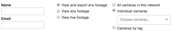
As mentioned previously, administrative access is important in considering and designing an organization or network schema. Organizational-level administrators have access to the entire dashboard, all networks, and organization-wide pages, including licensing, inventory, creating/deleting networks, etc. Network-level administrators have the ability to access and manage everything within a network in an organization. This means they can see and modify general settings. Organization and network-level admins can be given read or write access. Camera-only admins have only access to cameras. Access can be granted to all cameras, individual cameras by name, or groups of cameras by tags. Permissions can be set to allow the user to view/export all footage, view all footage, or view only live footage.
Determine Quality and Retention for Each Camera
It is important to create a policy for video quality and retention for each camera. Policies may differ based on camera location, purpose, and what is being recorded. It is possible that all cameras may have the same policy, but there may be different needs for different groups of cameras.
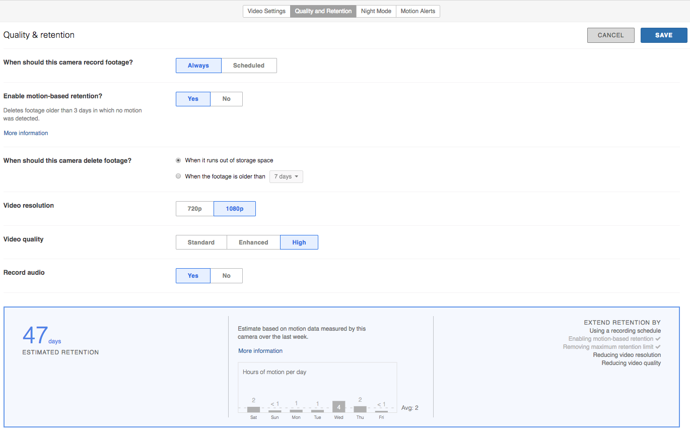
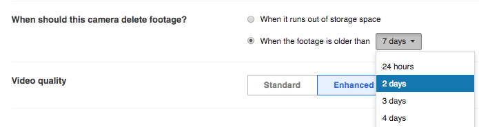
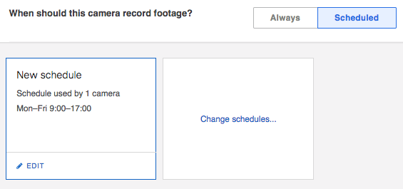
In most cases, having at least some amount of recorded video is recommended. However, some locations and/or countries have very specific privacy laws; if this is the case, it is important to configure cameras to adhere to these laws. By default, Meraki cameras are set to always record footage, and delete only when space runs out (files follow a first-in-first-out, or FIFO, methodology). When needed, cameras can be set to record based on a schedule, and delete footage after a certain period of time. Example configurations for footage deletion and recording schedules can be seen below:
Motion-based retention can be enabled when feasible to extend the storage capacity for each camera. When enabled, the camera will always retain the most recent 72 hours of continuous footage recorded. After three days, video clips which do not contain any motion are automatically deleted, allowing the camera to store only footage of interest and increase retention. Motion-based retention is disabled by default.
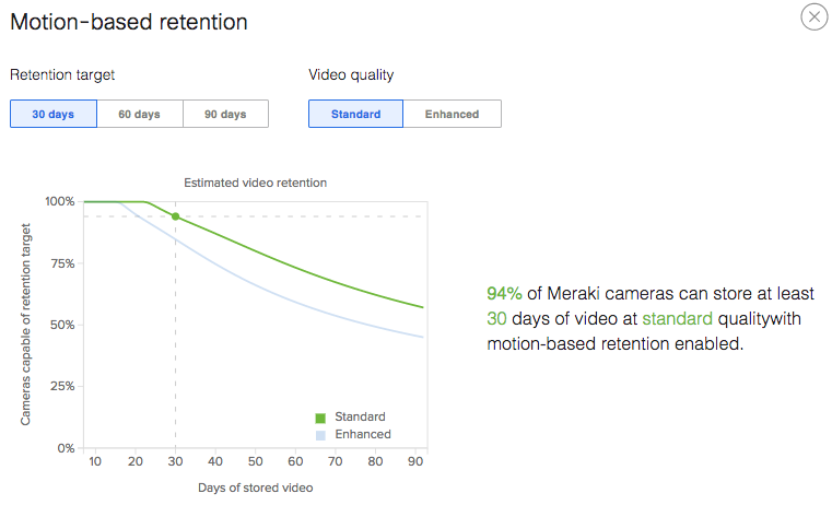
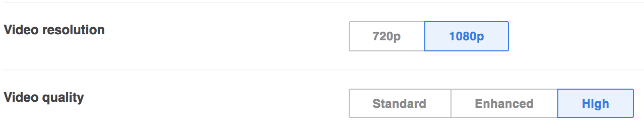
Video resolution isn’t a big mystery: the larger number in 1080p vs 720p means that there are more lines in the frame of video being displayed. Higher resolution means higher bandwidth and storage requirements. The same holds true in frame rates or fps. Estimated retention is automatically calculated for each camera based on its current settings. These settings include 24x7, scheduled, or motion-based retention, along with video resolution and quality. Higher video resolution and quality is recommended, but isn’t always necessary in all deployments.
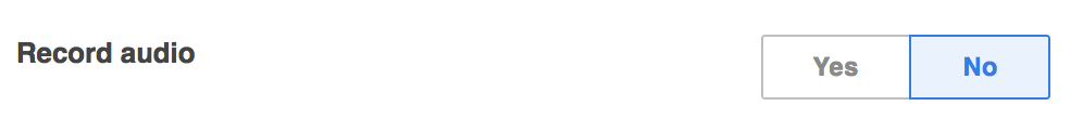
Some Meraki MV cameras, like the MV12, can record audio. Audio recording is disabled by default. Determine if recording audio is a requirement and if so, if it is legal. Privacy laws vary from country to country, and not adhering to laws can result in serious repercussions.
Low light Mode Configuration
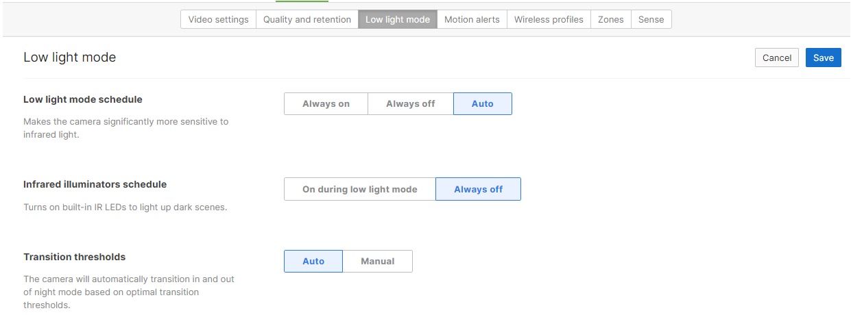
When ambient light falls below certain thresholds, the cameras can switch to Low light mode, allowing them to be more sensitive to infrared illumination. By default Low light mode is set to “auto” and the built-in infrared illuminators of the Meraki MV cameras are set to “on during Low light mode.” For first generation cameras, “Transition thresholds” can be adjusted to fine tune night (and day) mode. By default, the transition thresholds are configured at 0.5 lux for night and 3.0 lux for day. Keeping default settings is recommended.
Second generation cameras will automatically transition in and out of Low light mode based on optimal transition thresholds. 2nd gen cameras will prefer Low light mode in low light environments as it provides a much higher video quality in regards to physical security. Low light mode allows for easier detection and classification of objects in the scene when video is reviewed for security purposes.
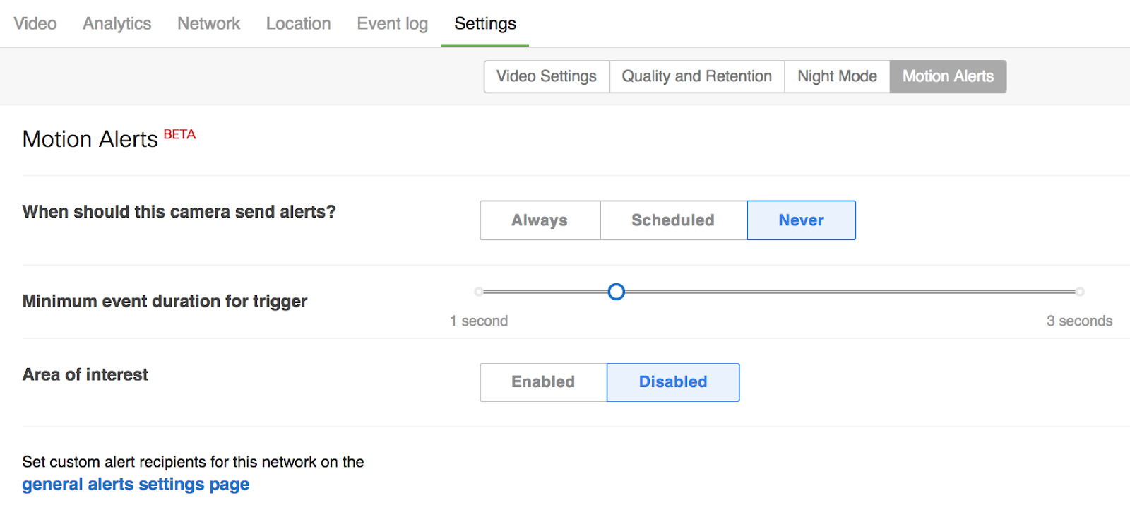
Motion Alerts
Motion alerts send notifications via email when motion is detected either within the frame or a selected region of a camera. These can be extremely useful in monitoring areas where tracking motion is important. Motion alerts can be configured to be sent always, or only during a certain schedule. Scheduling motion alerts is useful when monitoring an area after hours. Motion alerts are disabled by default.
Create an Inventory List for All Cameras
This is multifaceted as it will help with pre-installation setup and deployment as well as help with post-installation documentation. Having something as simple as an excel spreadsheet listing a camera by model number, serial number, name, MAC address, location description, and other details in the PSSRP is a big plus when coordinating efforts with multiple hands. This can easily be done with the CSV export tool within the Meraki Dashboard from a network or organization inventory.
Define Necessary Video Walls for Monitoring Feeds
Video walls can be configured to allow for simultaneous viewing of multiple camera feeds. It may not be possible to determine all video wall needs prior to implementation, as customers may not know what they want or need. However, it is useful to have some basic video wall needs defined, as it is helpful in conveying how the system can operate/what it can do.
Determine which Users Need Alerts
A big advantage of the Meraki MV system is that the camera device (node) functions in relationship to other equipment in the dashboard. This enables alerting/notification of administrators in the event that the system goes offline. In many other systems, the security cameras, video management system, and storage solutions operate independently in silos. If one part of the system fails, there may not be a process to alert or notify administrators of the failure. This results in many administrators not knowing that a camera or storage system is offline until there is a need to pull footage. As part of the deployment, determine which users should be notified of issues, and configure alerts to be sent in the event of operational disruptions.
Dedicated Security or Monitoring Station(s)
Monitoring stations are common in instances that security guards need to watch multiple areas of a facility or campus. The Meraki dashboard can be configured with video walls to view up to 16 simultaneous camera streams at once per browser. System requirements for machines running video walls are available in our Hardware Guidelines for MV Streaming Workstations document.
Implementation and Installation of Meraki MV Cameras
Pre-Install Preparation for MV Cameras
Powering MVs
MV Cameras are powered by Power over Ethernet (PoE) via the ethernet cable. The consumption for MV12 and MV21 is within the 802.3af standard (PoE). The outdoor camera MV71 requires 802.3at (PoE+).
Time Synchronization
A vital part of a security camera system is time synchronisation for each camera. This is done automatically through the Meraki dashboard. No local NTP server necessary.
Assigning IP Addresses
Like any other network device, the MV camera requires an IP Address. MV units must be added to a subnet that uses DHCP and has available DHCP addresses to operate correctly. At this time, the MV cameras do not support static IP assignment. Consider using DHCP reservations if you need the IP address to remain constant.
Check and Configure Firewall Settings
If a firewall is in place, it MUST allow outgoing connections on particular ports to the Meraki dashboard. The most current list of outbound ports and IP addresses for your particular organization can be found on the Firewall information page.
DNS Configuration
Each MV will generate a unique domain name to allow for secured direct streaming functionality. These domain names resolve an A record for the private IP address of the camera. Any public recursive DNS server will resolve this domain. If using an on site DNS server, please allow *.devices.meraki.direct or configure a conditional forwarder so that local domains are not appended to *.devices.meraki.direct and these domain requests are forwarded to Google public DNS.
Configuring a Network in Dashboard
All dashboard configurations should be done prior to installing any cameras. This allows the camera to associate with the correct organization/network in dashboard and download its configuration.
The following is a brief overview of the steps required to add an MV to your network. For detailed instructions on creating, configuring and managing Meraki Camera networks, refer to the online documentation (https://documentation.meraki.com/MV).
-
Login to http://dashboard.meraki.com. If this is your first time, create a new account.
-
Find the network you want to add your cameras to, or create a new network.
-
Add your cameras to your network. You will need your Meraki order number (found on your invoice) or the serial number of each camera, in an “xxxx-xxxx-xxxx” format, located on the bottom of the unit.
-
Verify that the camera is now listed under Cameras > Monitor > Cameras.
-
For an easy way to view and configure, install the Meraki App on your smartphone or tablet.
Note: During first-time setup, MV cameras will automatically update to the latest stable firmware. Some features may be unavailable until this automatic update is completed. This process may take up to 10 minutes, as it also includes whole-disk encryption. If you view cameras in dashboard during the setup, you may see the error message “Could not reach camera" while attempting autofocus. You will need to wait until the camera finishes upgrading to the latest stable firmware to use this feature. Please do not unplug cameras until they fully complete the upgrade process.
Installing and Configuring MV Cameras
Note: Leave the plastic film cover on all lenses until installation is complete. Take photos of installed cameras for reference. Add a name and physical address to each camera.
Installation Steps
-
Depending on your camera model, please follow the installation instructions in the respective Installation Guide.
-
Adjust and focus the camera.
-
Computer (use any operating system and any browser - no plugins needed)
-
Configure various video settings based on your design principles (see Design section):
-
Restrict the video viewing and export permissions for administrators as described here.
Post-Implementation and Troubleshooting
Run Dark Mode
Run dark disables the LED lights on all MVs. This feature is useful in situations where the lights may be annoying, distracting, or overly conspicuous. For example, the LEDs can be disabled to prevent outdoor MVs from drawing attention at night. To enable dark mode, add the tag “run_dark” to the camera. More details can be found in our Dark Mode documentation.
Troubleshooting IR Reflections
All Meraki MVs, with the exception of the MV32, are equipped with infrared (IR) illuminators. These can be turned on in Low light mode and used to provide an illuminated view. If the picture appears too blurry, please follow this Video Quality Troubleshooting guide.