
Meraki Campus LAN; Planning, Design Guidelines and Best Practices
Introduction
The Enterprise Campus
The enterprise campus is usually understood as that portion of the computing infrastructure that provides access to network communication services and resources to end-users and devices spread over a single geographic location. It might span a single floor, building or even a large group of buildings spread over an extended geographic area. Some networks will have a single campus that also acts as the core or backbone of the network and provide inter-connectivity between other portions of the overall network. The campus core can often interconnect the campus access, the data centre and WAN portions of the network. In the largest enterprises, there might be multiple campus sites distributed worldwide with each providing both end-user access and local backbone connectivity. From a technical or network engineering perspective, the concept of campus has also been understood to mean the high-speed Layer-2 and Layer-3 Ethernet switching portions of the network outside of the data centre. While all of these definitions or concepts of what a campus network is are still valid, they no longer completely describe the set of capabilities and services that comprise the campus network today.
The campus network, as defined for the purposes of the enterprise design guides, consists of the integrated elements that comprise the set of services used by a group of users and end-station devices that all share the same high-speed switching communications fabric. These include the packet-transport services (both wired and wireless), traffic identification and control (security and application optimization), traffic monitoring and management, and overall systems management and provisioning. These basic functions are implemented in such a way as to provide and directly support the higher-level services provided by the IT organization for use by the end-user community.
This document provides best practices and guidelines when deploying a Campus LAN with Meraki which covers both Wireless and Wired LAN.
Wireless LAN
Planning, Design Guidelines and Best Practices
Planning is key for a successful deployment and aims in collecting/validating the required design aspects for a given solution. The following section takes you through the whole design and planning process for Meraki Wireless LAN. Please pay attention to the key design items and how this will influence the design of WLAN but also other components of your architecture (e.g. LAN, WAN, Security, etc).
Planning Your Deployment
The following points summarizes the design aspects for a typical Wireless LAN that needs to be taken into consideration. Please refer to Meraki documentation for more information about each of the following items.
- Get an estimation of the number of users per AP (Influenced by the AP model, should be the outcome of a coverage survey AND a capacity survey)
- Determine the total number of SSIDs that are required (do not exceed 5 per AP or generally speaking per "air" field such that 802.11 probes of no more than 5 SSIDs compete for airtime)
- For each of your SSIDs, determine their visibility requirements (Open, Hidden, Scheduled, etc) based on your policy and service requirements
- For each of your SSIDs, determine their association requirements (e.g Open, PSK, iPSK, etc) based on the clients' compatibility as well as the network policy
- SSID encryption requirements (e.g WPA1&2, WPA2, WPA3 if supported, etc). Please verify that it's supported on all clients connecting to this SSID and choose the lowest common denominator for a given SSID.
- Client Roaming requirements (if any) per SSID and how that will reflect on your Radio and network settings (e.g. Layer 2 roaming, Layer 3 roaming, 802.11r, OKC, etc). Review recommendations and pay attention to caveats mentioned in the following section.
- Wireless security requirements per SSID (e.g Management Frame Protection, Mandatory DHCP, WIPS, etc)
- Splash pages needed on your SSIDs (e.g. Meraki Splash page, External Captive Portal, etc) and what is the format of your splash page (e.g. Click through, sign-on challenge, etc)
- Splash page customizations (e.g welcome message, company logo, special HTML parameters, etc)
- Is it required to have Active Directory Integration for any of your SSIDs (What is the connectivity to AD server? IP route, VPN ,etc)
- Do you require an integration with a Radius Server (What is the connectivity to Radius server, How many Radius servers, Do you need to proxy Radius traffic, Any special EAP timers, etc, Will CoA be required, Dynamic Group Policy assignment via Radius, Dynamic VLAN assignment via Radius, etc)
- Client IP assignment and DHCP (Which SSID mode is suitable for your needs, which VLAN to tag your SSID traffic, etc)
- If you are tagging SSID traffic, ensure that the Access Point is connected to a trunk switch port and that the required VLANs are allowed
- Do you need to tag Radius and other traffic in a separate VLAN other than the management VLAN? (Refer to Alternate Management Interface)
- What are your traffic shaping requirements per SSID (e.g Per SSID, per Client, per Application)
- What are your QoS requirements per SSID (Per Application settings). Remember, you will need to match this on your Wired network.
- Do you need group policies? (e.g. Per OS group policy, Per Client group policy, etc)
- What are the wired security requirements per SSID (e.g Layer 2 isolation, IPv6 DHCP guard, IPv6 RA guard, L3/7 firewall rules, etc)
- Are you integrating Cisco Umbrella with Meraki MR (Requires a valid LIC-MR-ADV license or follow the manual integration guide)
- How do you want your SSIDs to be broadcasted (e.g. On all APs, specific APs with a tag, all the time, per schedule, etc)
- Is BLE scanning required?
- Is BLE beaconing required (What UUIDs and assignment method)
- What Radio profile best suits your AP(s) (e.g Dual-band, Steering, 2.4GHz off, channel width, Min and Max Power, Bit rate, etc)
- Do you need multiple Radio profiles (e.g. per zone, per AP, per location, etc)
- If you require end-to-end segmentation inclusive of the Wireless edge (Classification, Enforcement, etc.) using Security Group Tags (Requires LIC-MR-ADV license)
- If enabling Adaptive Policy, choose the assignment method (Static vs Dynamic via Radius) and SGT per SSID
- Follow the guidance when configuring your Radius server (e.g. Cisco ISE) to enable dynamic VLAN/Group-Policy/SGT assignment
- For energy saving purposes, consider using SSID scheduling
Design Guidelines and Best Practices
To digest the information presented in the following table, please find the following navigation guide:
- Item: Design element (e.g. Wireless roaming)
- Best Practices: Available options and recommended setup for each (e.g. Bridge mode for seamless roaming)
- Notes: Additional supplementary information to explain how a feature works (e.g. For NAT mode SSID, the AP runs an internal DHCP server)
- Caution/Caveat/Consideration: Things to be aware of when choosing a design option and/or implications to the other network components (e.g. Layer 3 roaming mode requires AP to AP access on port UDP 9358)
Please pay attention to all sections in the below table to ensure that you get the best results of your Wireless LAN design
| Item | Best Practices | Notes | Caution/Caveat/Consideration |
MR AP Management VLAN
|
Dynamic IP Assignment (DHCP) for zero-touch provisioning (untagged traffic to the upstream switch port and then DHCP discover in the configured native VLAN) Static IP Assignment; Either pre-stage AP or provide DHCP and then change settings in dashboard. It is recommended (where possible) to assign a Management VLAN per zone (e.g. Floor, communal area, etc) This is for roaming and client balancing purposes |
This management VLAN must be able to access the public internet. Read more here on the required IPs and Ports
|
For Dynamic IP assignment, make sure the upstream switch port has the correct native VLAN settings. For Static IP assignment, make sure the chosen VLAN is allowed on the upstream switch port. |
|
Use this feature if your Radius, SNMP and Syslog servers are not accessible via the public internet. Ensure that there's IP communication between the alternate management interface VLAN and your server(s) (e.g. Radius, SNMP and Syslog) |
The same Alternate Management Interface VLAN will be used for all APs in the same dashboard network. The Alternate Management Interface IP address can be customized per AP. |
The AP Management VLAN still requires access to the internet regardless of enabling/disabling the Alternate Management Interface The Alternate Management Interface VLAN must be enabled on the upstream switch port which has to be configured in trunk mode |
|
Number of Users per AP |
Perform a coverage survey AND a capacity survey Determine the number of devices per user and their types |
Influences the model and quantity of your Access Points | Narrow band (e.g. 20Mhz) for higher density deployments |
Total Number of SSIDs |
Collapse to fewer SSIDs (Do not exceed 5 per AP competing for the same airtime, best practice is to stay within 3 SSIDs) | Leverage Dynamic VLAN assignment (Requires an external Radius server such as Cisco ISE) | More SSIDs will lead to higher airtime overhead. Other considerations here |
SSID Visibility Requirements (e.g. Public, Hidden, Scheduled, etc) |
Hidden or Public (your choice) but consider zoning them to specific APs. This can add extra work for IT administrators because they will have to go to each machine and manually configure the SSID, rather than telling users which network to connect to and the password.
|
Leverage AP tags to create SSID broadcasting zones
|
SSIDs should be hidden if they are not meant to be publically broadcast (e.g. New brand, site, etc) Please note that hidden SSIDs will still be broadcasting 802.11 probes and thus is not considered to add any security benefit |
SSID Association Requirements (e.g. Open, PSK, iPSK, etc) |
Each SSID should be serving a use case (Corp users, Contractors, IoT, etc) rather than a network segment | Leverage Cisco ISE for a granular experience per user per SSID | All clients must support the selected option (e.g. |
SSID Encryption Requirements (e.g WPA1&2, WPA2, WPA3, etc) |
Choose the most secure but lowest common denominator for a given SSID | Always refer to firmware changelog | Please verify that it's supported on all clients connecting to this SSID |
Client Roaming Requirements per SSID (Layer 2, Layer 3, Layer 3 with concentrator)
|
Layer 2 roaming with Bridge mode offers the most seamless roaming experience when using 802.11r (aka FT) Layer 2 roaming can be achieved using Bridge mode SSIDs It is recommended to limit roaming to a specific zone, e.g. a floor plan (to reduce your broadcast domain) |
Layer 2 roaming requires that all APs in a roaming zone have access to the client's VLAN All APs within a roaming zone must be in the same dashboard network |
Radio settings; aim for 15-25 dB SNR Caution with your VLAN size (larger VLANs lead to larger broadcast domain) Do not prune the client's VLAN on any of the switch ports where the participating APs are connected Wi |
Layer 3 Roaming with 802.11r & OKC |
Use Layer 3 roaming with concentrator and enable Fast reconnect on client
|
Refer to Layer 3 roaming best practices
|
Requires IP communication with Meraki Registry (Source port range UDP 32768-61000 and destination port UDP 9350-9381) Requires IP communication with concentrator to establish tunnels (Source/Destination port range UDP 32768-61000) Please ensure proper IP communication on all required ports. Also, pay attention to the concentrator deployment mode (i.e. Routed mode vs One-armed mode) as this will influence the IP address of packets that are breaking out centrally (e.g. DHCP, DNS, Radius, etc). Read more here |
Layer 3 Roaming with PSK |
User layer 3 roaming (aka distributed roaming) | Please refer to Layer 3 roaming best practices | APs will exchange roaming database using port UDP 9358 |
Management Frame Protection (802.11w) |
Choose Enabled option if not supported on all clients connecting to this SSID | Applies to robust management frames | Required option will prevent clients that do not support PMF from joining this SSID |
Mandatory DHCP |
Mandatory DHCP enforces that clients connecting to this SSID must use the IP address assigned by the DHCP server. Clients who use a static IP address won’t be able to associate. Choose Enable Mandatory DHCP if this is part of your security requirements. |
The default setting for this feature is disabled. Wireless clients configured with static IPs are not required to request a DHCP address.
|
All 802.11ac Wave 2 capable MR access points running MR 26.0 firmware or later support this feature.
|
WIPS (aka Air Marshal) |
Air Marshal mode allows network administrators to design an airtight network architecture that provides an industry-leading WIPS platform in order to completely protect the airspace from wireless attacks such as:
You specify whether or not clients are able to connect to rogue SSIDs. If you select block clients from connecting to rogue SSIDs by default, then devices will be automatically contained when attempting to connect to an SSID being broadcast by non-Meraki AP seen on the wired LAN. This provides greatest level of security for the wireless network. |
On MRs with a scanning radio, Air Marshal will not contain Rogue and Other SSIDs seen by the scanning radio if those SSIDs are on a DFS channel. However, if the client-serving radio of the MR is operating on a DFS channel that matches that of the Rogue or Other SSIDs, Air Marshal will contain those SSIDs on that DFS channel if configured to do so. |
6 GHz containment will not work because 6 GHz uses protected management frame and it would not be possible to contain the clients over the air |
Splash Page (None, Click-through, Sign-on, etc) |
Splash page frequency to control the user admission on the network |
Some clients (e.g. Printers) won't support Splash pages Where applicable, Radius traffic will be sourced from the Meraki dashboard (not the AP). Check the full traffic flow here |
|
Splash Page Customization |
If you require a fully customized experience, it is recommended to deploy an external captive portal and leverage the EXCAP API. | Check this list for allowed HTML tags and attributes | |
Active Directory Integration |
Ensure IP communication path to your Active Directory server(s). It is recommended to access the Active Directory server via VPN as the traffic is not encrypted | Ports used: 3268, 389 | Please note that traffic is sent unencrypted |
Radius Server Integration |
Ensure IP communication path to your Radius server(s). It is recommended to access the Radius server via VPN as the traffic is hashed using the Radius secret EAP timers should match those on your Radius server. Where applicable, Group policy can be sent back in a Radius attribute (e.g. Filter-Id) as a String. Group Policies can also assign VLANs to wireless users Where applicable, VLAN tag can be sent back in a Radius attribute (Tunnel-Private-Group-ID) with Tunnel-Type (VLAN), and Tunnel-Medium-Type (IEEE-802) attributes in the Access-Accept message IF dashboard is configured with “RADIUS response can override VLAN tag" Where applicable, CoA (Change of Authorization) can be used to adjust an active client session. CoA is a RADIUS code 43 frame. |
If your deployment uses CoA ensure you enable Cisco ISE even if ISE is not used, otherwise audit-session-id is not included and the CoA exchange may not work. |
CoA is only supported on the following SSID modes: NAT mode, Bridge mode, Layer 3 Roaming, Layer 3 Roaming with a Concentrator, VPN CoA is not supported on MR Repeaters.
For CoA with Splash page, Radius server sends CoA messages to Meraki's FQDN on port UDP 799 With MR26+, the client won't be disconnected (i.e. No new DHCP request) Cloud Radius Proxy does not support CoA |
|
Please ensure that:
For Fail-Closed (i.e. Only clients that previously successfully authentication and verified with LDAP to be authorized on the Wireless network), Choose the LDAP option set to Verify Certificate CN with LDAP. For Fail-Open, leave the LDAP option set to Do not verify certificate with LDAP. (please note that in this case, any wireless device that presents a valid certificate will be able to connect to the SSID regardless of the permissions set for that device/user) If you wish to check if the certificate presented to the MR is revoked, set OCSP to Verify Certificate with OCSP and set the OCSP Responder URL the MR can use to check the certificate against. |
MR uses the certificate signed by QuoVadis CA (before March 23rd 2021) and IdenTrust Commercial Root CA 1 (after March 23rd 2021) and the client uses the certificate signed by their own CA Password supported types:
Certificate supported types:
Multiple LDAP servers can be used for different SSIDs For more information about Root CAs and other related info, please refer to this documentation article. |
Alternative Management Interface can be used to communicate with the LDAP server only. It cannot be used to communicate with the OCSP server With this auth method, an external RADIUS server is not involved in this process and is not needed. The RADIUS server on the MR will handle 802.1X authentication instead MR27+ firmware is not supported on all MR models. Please refer to the to Product Firmware Version Restrictions EAP-MSCHAPv2 is not supported with Meraki Local Auth Currently, the MR access point cannot check if a user’s account is locked or disabled in the Active Directory. In addition, it’s not possible to “pre-cache” specific clients only. By default, all clients will be cached. A maximum of one LDAP server is currently supported. Multiple LDAP servers can be used for different SSIDs Secure LDAP (LDAPS) is not currently supported If the Verify Certificate CN with LDAP option is set only clients that previously successfully authenticated and verified with the LDAP server to be authorized for wireless access will be able to connect to the SSID (i.e. any clients that have not been successfully authenticated and, therefore, not cached will be denied access to the SSID if the LDAP server is down) |
|
|
Use NAT mode SSID if your client(s) only require access to the Internet Use NAT mode SSID if your network does not have a DHCP server Use NAT mode SSID if you network has a DHCP server but without enough address space |
In NAT mode, Meraki APs run as DHCP servers to assign IP addresses to wireless clients out of a private 10.x.x.x IP address pool behind a NAT. By default, client(s) will use the same DNS handed out to the AP for DNS queries. This can be Customized to use specific DNS server(s) if required. |
Do not use NAT mode SSID if your client(s) require access to local wired or wireless resources All clients will be assigned with an IP address in the range 10.0.0.0/8 (This cannot be customized) All client traffic will be NAT'd to the AP's management IP and sent untagged to the upstream switch port VLAN tagging is not supported in NAT mode SSID No communication between wired and wireless clients Layer 2 discovery protocols (e.g. LLDP) cannot be used to discover hosts on the wired or wireless network Do not use NAT mode SSID if your client(s) do not support NAT Traversal (e.g. VPN clients) Roaming is not supported in NAT mode SSID |
|
|
It is recommended to use a default VLAN tag on a bridge mode SSID to avoid traffic being tagged in the AP's management VLAN Use Bridge mode if wired and wireless clients in the network need to reach each other (e.g. Mobile phone needs to access a wired printer) Use Bridge mode if multicast/broadcast traffic is required to flow between wireless and wired Use Bridge mode if your client(s) do not support NAT Traversal Use Bridge mode if you need to tag your SSID in a specific VLAN (static or dynamic) Use Bridge mode if you're using IPv6. Check IPv6 bridging for more information Bridge mode is recommended for seamless roaming across Meraki MR Access Points (Within the same layer 2 domain, i.e. same VLAN). Leverage Bridge mode VLAN tagging via AP tag to group APs together into a roaming zone; e.g. a floor plan (For example, All APs in lobby area tagged with "Lobby_AP" and APs in Sales area tagged with "Sales_AP" then the Bridge SSID can tag traffic in VLAN 10 for AP tagged with Lobby_AP and in VLAN 20 for AP tagged with Sales_AP). This will provide the best experience for seamless roaming with 802.11r and OKC as users roaming across a roaming zone will not require a new DHCP request. Avoid using large VLANs (e.g. /16) as this will create a larger broadcast domain. Instead, assign a VLAN per zone (e.g. floor plan) |
If no VLAN tag is specified for the SSID, traffic will be sent untagged to the upstream switch port. It is most likely that it will be configured with the management VLAN as the native VLAN. This is the VLAN that will be used to tag the SSID traffic in this case. VLANs assigned via Group Policies supercedes those configured on the Acess control Page. Group policies can either be assigned statically to clients or dynamically via a Radius attribute |
Adult Content Filtering not supported on Bridge mode Remember to allow the whole range of tagged VLANs (static AND dynamic) on the upstream switch port(s) where your AP is connected (i.e. upstream switch ports must be configured in trunk mode) |
|
Layer 3 Roaming Mode SSID (aka Distributed Layer 3 Roaming) |
Ensure that all APs in a roaming zone can communicate with each other using port UDP 9358 and using ICMP. Distributed layer 3 roaming is best for large networks with a large number of mobile clients. It is recommended to use the "Test" button on dashboard after any change done on your switches Choose distributed layer 3 roaming over Layer 3 roaming w/ concentrator if:
|
A client's anchor AP will timeout after the client has left the network for 30 seconds APs will attempt to do a broadcast domain mapping by sending broadcast frames of type 0x0a89 sent every 150 seconds. Repeaters don’t have their own IP address, so they cannot be anchor APs. When a client connects to a repeater, the repeater becomes the client’s hosting AP, and the repeater assigns its gateway as the client’s anchor AP.
|
Fast roaming protocols such as OKC and 802.11r are not currently supported with distributed layer 3 roaming. The best roaming performance will be using Layer 2 roaming with 802.11r. All APs in a roaming zone must be in the same dashboard network (but can be in any network segment as long as they can communicate using IP and port UDP 9358) A client's anchor AP will timeout after the client has left the network for 30 seconds. An AP could theoretically broadcast BCD announcement packets to all 4095 potentially attached VLANs, however it will limit itself to the VLANs outlined below:
With Wireless Meshing; Repeaters don’t have their own IP address, so they cannot be anchor APs. When a client connects to a repeater, the repeater becomes the client’s hosting AP, and the repeater assigns its gateway as the client’s anchor AP. |
|
Ensure that all APs in a roaming zone can communicate with Meraki Key registry on destination port UDP 9350-9381 (source port UDP 32768-61000) - Check traffic flow here Ensure that all APs in a roaming zone can communicate with their concentrator on destination port UDP 32768-61000 (source port UDP 32768-61000) - Check traffic flow here It is recommended to have concentrator resiliency with one of the following options:
It is recommended to use the same concentrator mode on ALL used concentrators (do not mix Routed and One-armed modes even for geo-resilient concentrators) In case of using Warm-spare concentrators, it is recommended to use an upstream VIP (virtual IP) to minimize disruption during tunnel failover Refer to the latest MX sizing guide for your concentrator(s) Choose Layer 3 roaming w/ concentrator over distributed layer 3 roaming if:
|
Each configured SSID will form a Layer 2 VPN tunnel to it's concentrator(s) (maximum two) With warm-spare concentrators, tunnels only form to the active unit (either to the physical assigned IP address to it's uplink OR to the virtual IP) Both Routed and One-armed Concentrator modes supported (More info here) Both MX and vMX concentrators can be used. With Routed mode concentrator:
With One-armed concentrator:
|
Sizing:
Resiliency:
Warm-spare design notes: With warm-spare concentrators, the two units need to exchange VRRP packets as follows:
Routed mode concentrator design notes:
One-armed mode concentrator design notes:
|
|
|
Recommended for small branch offices, teleworker or executive home offices, temporary site offices (eg. construction sites) with no more than 5 users per AP Where possible (e.g. In case of an onsite NGF such as Meraki MX Security and SD-WAN appliance), configure split tunneling as opposed to full tunneling for better network performance. Ensure that all APs in a roaming zone can communicate with Meraki Key registry on destination port UDP 9350-9381 (source port UDP 32768-61000) - Check traffic flow here Ensure that all APs in a roaming zone can communicate with their concentrator on destination port UDP 32768-61000 (source port UDP 32768-61000) - Check traffic flow here It is recommended to have concentrator resiliency with one of the following options:
It is recommended to use the same concentrator mode on ALL used concentrators (do not mix Routed and One-armed modes even for geo-resilient concentrators) In case of using Warm-spare concentrators, it is recommended to use an upstream VIP (virtual IP) to minimize disruption during tunnel failover Refer to the latest MX sizing guide for your concentrator(s) |
Each configured SSID will form a Layer 2 VPN tunnel to it's concentrator(s) (maximum two) With warm-spare concentrators, tunnels only form to the active unit (either to the physical assigned IP address to it's uplink OR to the virtual IP) Both Routed and One-armed Concentrator modes supported (More info here) Both MX and vMX concentrators can be used. With Routed mode concentrator:
With One-armed concentrator:
|
Sizing:
Resiliency:
Warm-spare design notes: With warm-spare concentrators, the two units need to exchange VRRP packets as follows:
Routed mode concentrator design notes:
One-armed mode concentrator design notes:
|
|
SSID Traffic Shaping |
It is recommended to apply traffic shaping settings on the access edge (i.e. on your Wireless APs) 5 Mbps is a good recommendation for per-client bandwidth limit in high-density environment (You can override this limit for specific devices and applications) Consider using SpeedBurst where applicable (enables bursts of four times the allotted bandwidth limit for five seconds) Dashboard offers default shaping rules which could be sufficient. Otherwise, you can create your own rules. (Rules are processed in top-bottom order) Traffic can be shaped based on:
WMM and QoS settings (e.g. DSCP, CoS) can be applied on:
FastLane can enhance the network performance by assigning wireless profiles to your clients Refer to this table for downstream QoS mappings and ensure this is consistent with your Access switch(s) settings. Also ensure that switchports used as uplinks for MRs are set to trust DSCP |
Traffic shaping can be applied using the following options:
Since traffic shaping can be set in different ways, dashboard will use the following order of policy (lowest to highest):
|
Traffic shaping is per flow (e.g. 5Mbps limit for Webex is applied per flow, so each client will be limited to 5Mbps Webex traffic) Traffic shaping is not for limiting the wireless data rate of the client but the actual bandwidth as the traffic is bridged to the wired infrastructure. MR APs will automatically perform a multicast-to-unicast packet conversion using the IGMP protocol. The unicast frames are then sent at the client negotiated data rates rather than the minimum mandatory data rates, ensuring high-quality video transmission to large numbers of clients. This can be especially valuable in instances such as classrooms, where multiple students may be watching a high-definition video as part of a classroom learning experience. MR APs will automatically limit duplicate broadcasts, protecting the network from broadcast storms. The MR access point will limit the number of broadcasts to prevent broadcasts from taking up air-time. This also improves the battery life on mobile devices by reducing the amount of traffic they must process. |
SSID Firewall Rules
|
L3/L7 firewall rules can be used to filter outgoing traffic Use Deny access to local LAN to prevent clients from accessing any LAN (RFC 1918) resources (DNS & DHCP are exempt) Use layer 2 isolation (bridge mode only) to prevent Wireless Clients communicating to each other IPv6 DHCP guard and IPv6 RA guard can be applied with MR28.1+ |
Layer 3 firewall rules on the MR are stateless and can be based on destination address and port Layer 7 firewall rules can either be category based or Application based NBAR is supported on WiFi6 Access Points with MR27.1+. Check firmware compatibility with your APs here Firewall Rules can be applied using the following options:
DHCP Guard has the following options:
Router Advertisement (RA) Guard has the following options:
|
MRs can have a maximum of 1800 firewall rules NBAR support requires the following:
Deny access to local LAN and layer 2 isolation (bridge mode only) Can only be applied on the global SSID settings (i.e. not configurable via a Group policy) |
Umbrella Integration |
There are two options for Umbrella integration:
|
When a Meraki SSID is initially linked, it will inherit the default Umbrella Policy, which will be the last policy in Umbrella's ordered list. Once a policy is assigned to a network device (SSID/group policy) in the Umbrella dashboard, any policies below the one selected for the network device will not be checked against. The policy list in Umbrella is read in a top-down order and once a match is found for the device ID, no other policies will be evaluated. More information can be found in Cisco Umbrella's Policy Precedence documentation. |
Cisco Umbrella has two potential endpoints that Meraki will send DNS traffic to: 208.67.222.222/32 and 208.67.220.220/32. Make sure that bi-directional UDP 443 to both of these addresses is allowed on any upstream devices. DNS exclusion is only available for SSIDs configured in Bridge Mode. For HTTPs blocking, blocked requests for HTTPS content will not load the Umbrella blocked page correctly. Instead, users will be presented with a generic "Webpage is not available" error.
|
Radio Planning |
Site Surveys:
For ceiling mounted APs:
For wall mounted APs:
Frequency Bands:
Radio Management:
DFS:
Antennas:
Please ensure that at any given time, channel utilization is kept below 50% as this will impact your network performance. There are important factors; 1) Utilization value and 2) Over how much time (i.e. is this consistent or just a burst) |
Radio samples are sent from Meraki APs to the cloud every second. With AutoRF, TX power can be reduced by 1-3 dB per iteration and is increased in 1 dB iterations For 2.4 GHz, Auto Power reduction algorithm allows TX power to go down only up to 5 dBm. For 5 GHz, Auto Power reduction algorithm allows TX power to go down only up to 8 dBm (If lower TX power is needed, APs can be statically set to lower power) AutoRF will only switch channels if there is high utilization and that there is a better channel available (Process runs every 15mins) Dashboard refers to 2.4Ghz Radio as radio: 0 and 5Ghz as radio: 1 Dashboard refers to the first configured SSID as vap: 0 and then each subsequent SSID as vap: x (you can configure up to 15 SSIDs on dashboard) CSAs will be used to move clients from one 20 Mhz or 40 Mhz channel to another (Does not apply to 80Mhz channels) When a DFS event occurs, all the APs in a network will switch to the next best channel (disconnecting all clients on DFS channels) If the non-802.11 utilization on one of the client-serving radios is 65% or greater for one minute, the dashboard will instruct the AP to change to a different channel. Client Balancing information is exchanged between APs on the LAN via Broadcast frames using UDP port 61111 Refer to this document to better understand signal propagation Understanding EIRP: EIRPWithout beamforming = transmit strength (dBm) + antenna gain (dBi) – cable loss (dB) For example; if you an AP's output power is 21dBm, the cable loss is 1dB, and the max EIRP for the band is 1W or 30dB, an antenna with a gain of up to 10dBi can be used within the legal maximum EIRP. EIRPWith beam orming = transmit strength (dBm) + antenna gain (dBi) + beamforming gain (3db) – cable loss (dB)
|
MR APs can be used in site survey mode A maximum of 50 RF profiles can be defined. When an AP is being deployed initially, it uses the default channels of 1 for 2.4 GHz and 36 for 5 GHz and the transmit power is set to Auto. These settings can be manually configured on the dashboard per AP before deploying wireless setup. Some legacy clients do not inspect CSAs (Please contact Meraki support to disable AutoChannel feature) Gateways serving active Meshed Repeaters will not change channels Ensure that APs participating in Client Balancing are on the same broadcast domain (e.g. a floor or a building may all share a common management VLAN) MR APs that do not support 80 MHz-wide channels will default to 40 MHz for their channel width RX-SoP is available only on Meraki 802.11 ac Wave 2 APs and higher After RF profiles have been assigned, TX power and channel assignment changes might take up to 60 minutes to reflect changes as calculations are done through Meraki dashboard Refer to the hardware install guides for guidance on antenna selection. Two identical antennas are necessary if using a 2-port antenna on the MR84 Please note that Radios on newer generations of MR access points (e.g. WiFi-6) have a higher sensitivity compared to older generations (e.g. WiFi-5 Wave 2) which might result in a higher number of DFS events detected by newer APs The Meraki Cloud assigns the appropriate regulatory domain information to each Meraki Access Point. Which bands and channels that are available for a particular Meraki Access Point depends on the model, indoor/outdoor operation, and the regulatory domain. Since the Meraki Cloud enforces the wireless regulations, the channel list on the Radio Settings Page will show the channels the access point is certified to use. For more specific certification and band information, please refer to the install guides and the regulatory information pamphlet included within the AP's original packaging |
|
We recommend that you perform a radio site survey before installing the equipment (involves temporarily setting up mesh links and taking measurements to determine whether your antenna calculations are accurate) It is generally recommended to allow auto-channel selection in networks with repeaters. However, each use case must lend itself to the specific requirements (antenna selection, frequency band, etc) Minimize the number of hops between Repeaters and Gateways (ideally single hop) Maximize the number of Gateways available in the vicinity of your Repeater (plan for no more than two repeater access points attached to each gateway access point - and - it is recommended that each mesh access point has at least three strong neighbors) Although it is not recommended to use manual channel selection for meshing, if you really need to do then it is advised to change on all Repeaters first then changing it on the Gateway. Use AP tags to disable un-desired SSIDs on a Repeater (By default the Repeater will broadcast all SSIDs of its Gateway) It is recommended to stage access points before deploying to ensure that they update to the latest firmware and download the proper configuration from the Meraki Dashboard. Once deployed, firmware and configuration updates may occur over the mesh network. Indoor Meshing Best Practices: Outdoor Meshing Best Practices:
|
Meraki APs will attempt to form a Meshing link if:
Meraki Repeater APs will search for a new Gateway if:
Data traffic over a Wireless Mesh link is encrypted using the Advanced Encryption Standard (AES) algorithm. Meraki APs in Repeater mode will automatically choose a gateway with the best mesh metric which is calculated based on the received mesh probes. Meraki APs in Gateway mode will broadcast mesh probes (Broadcast frames with different bit rates and varying sizes every 15 seconds on both 2.4 and 5 GHz) Once the AP goes in the mesh mode, The AP scans all channels to collect info from all neighbors. If a valid neighbor (in-network AP or Meraki AP) is found, it goes to that channel. The configured channel has higher precedence if a valid neighbor is found on it. If no valid neighbor is found at all from all channels, it stays on the configured channel.
While it is not possible to select which frequency band should be used for meshing, it is possible to manually adjust channel selections to direct the AP toward a desired behavior. To do this, refer to the article on manually changing channels in a mesh network. If it is desired for two APs to mesh on 5Ghz as opposed to 2.4Ghz, then the APs should both be set to the same 5Ghz channel, but different 2.4Ghz channels. Keep in mind though that a frequency band cannot be allocated specifically for meshing, and both bands will still be available for servicing clients unless the SSID is configured to use the 5Ghz band only. |
Only Cisco Meraki APs can function as repeaters and gateways. Wireless MX security appliances, Z-Series teleworker gateways, and third-party APs cannot participate in a wireless mesh. Wireless Meshing utilizes both bands. (A frequency band cannot be allocated specifically for meshing) Only way to force meshing on 5 GHz is to disable the 2.4GHz radio A Repeater meshing to a Meraki AP Gateway in the same dashboard network will use its gateway to send both control plane and data plane traffic. A Repeater meshing to a Meraki AP Gateway that does not belong to the same dashboard network will use its gateway to send only control plane traffic. It is not possible to configure a static IP address for a repeater AP; doing so will automatically designate the device as a gateway instead of a repeater. Wireless meshing reduces throughput by approximately 50%, per hop (i.e. APs in its way to reach a valid gateway) It is not recommended to disable meshing to account for unexpected failures on the wired network Environmental factors, like moisture and wind affect performance and link quality Make sure the AP is grounded properly to prevent static buildup and to protect against other electrical issues The Meraki PoE Injector must be deployed indoors as it is not waterproof or ruggedized Conform with the device's listed operating temperature (Refer to datasheets) |
|
|
Bluetooth scanning enhances location analytics by giving you a holistic view of both 802.11 and Bluetooth clients Bluetooth beaconning is useful for client engagement use cases Best practices related to Meraki MT sensors:
|
For Meraki MT sensors, only MR WiFi6 and Wifi 5 Wave 2 access points can be used as gateway
|
||
|
It is recommended to configure a per-client limit to ensure that real time applications do not fight for bandwidth on the SSID It is recommended to configure traffic shaping rules (either default or custom) for real-time applications It is recommended to configure your upstream switches (e.g. Meraki MS product family) to trust incoming DSCP values from Meraki access points If your SSID is configured in Layer 3 roaming w/ concentrator mode, it is recommended that the traffic is terminated on a Voice VLAN on the far end and that you ensure that QoS is configured appropriately at the far-end Follow these steps as VoWiFi best practices:
|
For other product-specific recommendations, please refer to this guide This FAQ guide can be useful to troubleshoot VoWiFi issues. |
Do not use NAT mode for VoWiFi Do not use Layer 3 Roaming mode for VoWiFi if you require 802.11r and OKC for your VoIP devices Do not use Layer 3 Roaming w/ concentrator if you do not wish for VoIP traffic to be tunneled to a central concentrator Setting the minimum bit rate to 12Mbps or higher will not support 802.11b legacy clients |
|
|
With MR24.5+ MR access points use either LLDP or CDP to negotiate power level. Hence, please make sure the upstream switch is configured to negotiate power level with LLDP or CDP Avoid running in low power mode as this will shut both the scanning Radio (which disables WIPS and AutoRF) as well as the Bluetooth Radio (which disables MT connectivity and BLE scanning and advertisements) Indoor Access Points can be powered by either:
Outdoor Access Points can be powered by either:
For energy saving purposes, consider using SSID scheduling and MS Port Schedules (where applicable) |
Full details on lower power mode can be found here
|
While in low power mode, the MR will disable its Air Marshal radio as well as one out of three transmit streams on the 2.4 GHz band (leaving two transmit streams still operating) In comparison, models without the dedicated scanning radio, such as the MR12/16/20/24/70, scan the whole spectrum every 2 hours when there are no clients associated. When low power mode is enabled the scanning radio function becomes disabled. Thus, not only are there no channel_scan events but AutoRF channel assignment can be negatively impacted. |
|
Adaptive Policy (aka AdP) |
Adaptive policy requires MR-ADV license which is only supported in PDL license model When deploying a combined network, please ensure that all devices (e.g. MR, MS390, MX) support AdP (HW and SW) To enable Radius based tagging (e.g. Cisco ISE), please ensure that the RADIUS attribute value pair (av-pair) uses the Cisco SGT AV-Pair presented in HEX value (e.g. cisco-av-pair:cts:security-group-tag=0fa0-00). This example sends back an SGT of 4000 |
AdP is supported with:
In a hybrid architecture (e.g. with Cisco Catalyst as Core), please refer to this configuration guide To enable CMD tagging on an upstream TrustSec capable switch, please to IOS-XE Trunk Port Configuration To sync Adaptive Policy between Dashboard and Cisco ISE, refer to this tool. |
Tagging is only supported in NAT and Bridge mode If the upstream switch is Meraki MS and the switch port where the MR is connected is not configured with Peer SGT capable, the MR will disable tagging for that AP. The same thing will happen if the upstream switch (regardless of its make or model) does not send Cisco MetaData (CMD) encapsulated traffic for a set number of frames. This is known as fail-safe (AP will completely disable tagging until tagging is enabled on the connected switch and encapsulation is observed on the incoming frames) The RADIUS assignment of group tags is done per-session and to operate will require the av-pair in every access-accept for the client. Please note that you CAN apply a default tag to the SSID and override it with a RADIUS response. |
|
SecureConnect automates the process of securely provisioning Meraki MR Access Points when directly connected to switch-ports on Meraki MS Switches, without the requirement of a per-port configuration on the switch
SecureConnect-capable MR access point connected to an MS switch enabled for SecureConnect should not be configured with LAN IP VLAN number |
Supported APs will start off only being able to reach dashboard on the switch management VLAN. The APs will have 3 attempts of 5 seconds each to authenticate. If this authentication fails, the switch's port will fall into a restricted state. This might show itself in a couple of ways:
|
The failed authentication can happen if the AP and switch are in different organizations, or if the AP is not claimed in inventory. Supported on (with 27.6) MR20, MR30H, MR33, MR42, MR42E, MR52, MR53, MR53E, MR70, MR74, MR84, MR45, MR55, MR36, MR46, MR46E, MR56, MR76, MR86 If you have a MR44 or MR46 please contact Meraki support to check for supportability For further information on supported MS switch models, please check here |
Wired LAN
Introduction
A traditional Campus LAN Solution will reflect a hierarchical architecture with the following layers:
- Access Layer
- Distribution Layer
- Core Layer
When designing your Wired Campus LAN, it is recommended to start planning in a bottom-up approach (i.e. start at the Access Layer and go upwards). This will simplify the design process and ensure that you have taken into account the design requirements from an end to end perspective. As always, the design process should be done in iterations revising each stage and refining the design elements until the desired outcome can be achieved.
Here's an explanation of each layer in details and what design aspects should be considered for each:
Access Layer
The access layer is the first tier or edge of the campus. It is the place where end devices (PCs, printers, cameras, and the like) attach to the wired portion of the campus network. It is also the place where devices that extend the network out one more level are attached—IP phones and wireless access points (APs) being the prime two key examples of devices that extend the connectivity out one more layer from the actual campus access switch. The wide variety of possible types of devices that can connect and the various services and dynamic configuration mechanisms that are necessary, make the access layer one of the most feature-rich parts of the campus network.
Distribution Layer
The distribution layer in the campus design has a unique role in that it acts as a services and control boundary between the access and the core. It's important for the distribution layer to provide the aggregation, policy control and isolation demarcation point between the campus distribution building block and the rest of the network. It defines a summarization boundary for network control plane protocols (OSPF, Spanning Tree) and serves as the policy boundary between the devices and data flows within the access-distribution block and the rest of the network. In providing all these functions the distribution layer participates in both the access-distribution block and the core. As a result, the configuration choices for features in the distribution layer are often determined by the requirements of the access layer or the core layer, or by the need to act as an interface to both.
Core Layer
The campus core is in some ways the simplest yet most critical part of the campus. It provides a very limited set of services but yet must operate as a non-stop 7x24x365 service. The key design objectives for the campus core must also permit the occasional, but necessary, hardware and software upgrade/change to be made without disrupting any network applications. The core of the network should not implement any complex policy services, nor should it have any directly attached user/server connections. The core should also have the minimal control plane configuration combined with highly available devices configured with the correct amount of physical redundancy to provide for this non-stop service capability.
The following table compares between the main functions and design aspects of the three campus layers:
| Access Layer | Distribution Layer | Core Layer | |
|
Main Function
|
|
|
|
|
Design Aspects
|
* Please remember to factor for both the total power budget required per switch AND the power standard(s) required |
|
|
Collapsed Core Layer
One question that must be answered when developing a campus design is this: Is a distinct core layer required? In those environments where the campus is contained within a single building—or multiple adjacent buildings with the appropriate amount of fiber—it is possible to collapse the core into the two distribution switches.
It is important to consider that in any campus design even those that can physically be built with a collapsed distribution core that the primary purpose of the core is to provide fault isolation and backbone connectivity. Isolating the distribution and core into two separate modules creates a clean delineation for change control between activities affecting end stations (laptops, phones, and printers) and those that affect the data center, WAN or other parts of the network. A core layer also provides for flexibility for adapting the campus design to meet physical cabling and geographical challenges.
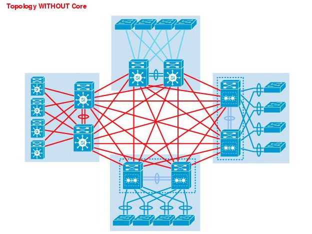
To illustrate the differences between having a Core layer and a Collapsed Core layer and how that relates to scalability, please see the following two diagrams:
Topology without Core Layer
Topology with Core Layer
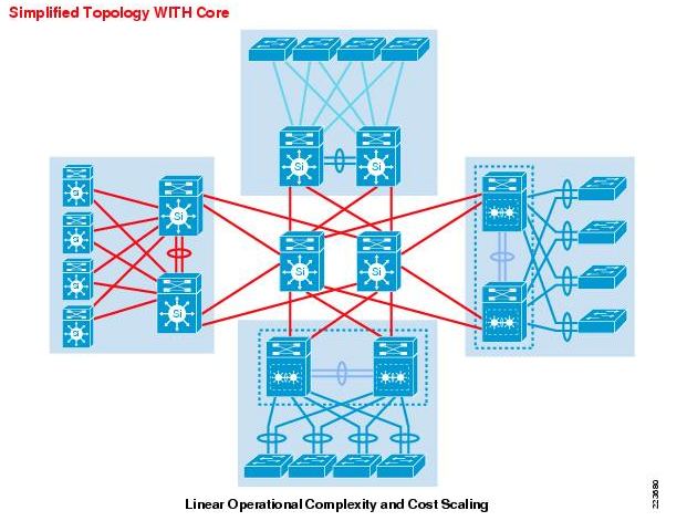
Having a dedicated core layer allows the campus to accommodate this growth without compromising the design of the distribution blocks, the data center, and the rest of the network. This is particularly important as the size of the campus grows either in number of distribution blocks, geographical area or complexity. In a larger, more complex campus, the core provides the capacity and scaling capability for the campus as a whole.
The question of when a separate physical core is necessary depends on multiple factors. The ability of a distinct core to allow the campus to solve physical design challenges is important. However, it should be remembered that a key purpose of having a distinct campus core is to provide scalability and to minimize the risk from (and simplify) moves, adds, and changes in the campus. In general, a network that requires routine configuration changes to the core devices does not yet have the appropriate degree of design modularisation. As the network increases in size or complexity and changes begin to affect the core devices, it often points out design reasons for physically separating the core and distribution functions into different physical devices.
As a general rule of thumb, if your Distribution Layer is more than one stack (or two distribution units); it is recommended to introduce a dedicated Core Layer to interconnect the Distribution Layer and all the other network components
It's recommended to follow a collapsed core approach if you're distribution layer is:
- A single switch (No HSRP/VRRP/GLBP needed in this case)
- A stack of MS switches (No VRRP/warm-spare needed in this case)
- A pair of MS switches (Enable routing on access layer if possible, more guidance given in the below sections, otherwise enable VRRP/Warm-spare)
- Two stacks of Cisco catalyst switches (e.g. C9500)
Otherwise, it's recommended to follow a traditional three-tier approach to achieve a more scalable architecture
Planning, Design Guidelines and Best Practices
Planning for your Deployment
The following points summarize the design aspects for a typical Wired LAN that needs to be taken into consideration. Please refer to Meraki documentation for more information about each of the following items
- Hierarchical design traditional approach with 3 layers (access, aggregation, core) vs more common approach with 2 layers (access, collapsed core)
- Port density required on your access layer
- What port type/speeds are required on your MDF layer (GigE, mgigE, 10GigE, etc)
- Patching requirements between your IDF and MDF (Electrical, Multi-mode fibre, Single-mode fibre, etc)
- Number of stack members where applicable (this will influence your ether channels and thus number of ports on aggregation layer)
- Stackpower requirements where applicable (e.g MS390, C9300-M, etc)
- Port density required on your aggregation/collapsed-core layer
- Switching capacity is required on your aggregation/collapsed-core layer
- Consider using physical stacking on the access layer (typically useful if they are part of an IDF closet and cross-chassis port channeling is required)
- Layer 3 routing on Access layer (typically useful to reduce your broadcast domain and helps with fault isolation/downtime within your network)
- Calculate your PoE budget requirements (Which will influence your switch models, their power supplies and power supply mode)
- Check your Multicast requirements (IGMP snooping, Storm Control, Multicast routing, etc)
- If you require DHCP services on your access layer (distributed DHCP as opposed to centralized DHCP)
- End-to-end segmentation (Classification, Enforcement, etc.) using Security Group Tags requires MS390 Advanced License
- What uplink port speeds are required on the access layer (GigE, mgigE, 10GigE, etc)
- If any ports on your switch(s) that needs to be disabled
- On your access switches designate your upstream connecting ports (For non modular switches, e.g Ports 1-4)
- On your access switches, designate your Wireless LAN connecting ports (e.g Ports 5-10)
- On your access switches, designate your client-facing ports (e.g Ports 12-24)
- On your access switches, designate ports connecting to downstream switches (where applicable)
- On your access switches, designate ports that should provide PoE (e.g. Connecting downstream Access Points, etc)
- On your aggregation switches, designate ports connecting to upstream network (For non modular switches, e.g Ports 1-4)
- On your aggregation switches, designate ports connecting to downstream switches (e.g. Ports 10-16)
- On your switches, designate ports that should be isolated (e.g Restrict access between clients on the same VLAN)
- On your switches, designate ports that should be mirroring traffic (e.g Call recording software, WFM software, etc)
- On your switches, designate ports that should be in Trusted mode where applicable (For DAI inspection purposes)
- Choose your QoS mark and trust boundaries (i.e where to mark traffic, marking structure and values, trust or re-mark incoming traffic, etc)
- All client-facing ports should be configured as access ports
- Ports connecting downstream Access Points can either be configured as access (e.g NAT mode SSID, untagged bridge mode SSID, etc) or trunk (e.g tagged bridge mode SSID)
- Using Port Tags can be useful for administration and management purposes
- Using Port names can be useful for management purposes
- Do you require an access policy on your access ports (Meraki Authentication, external Radius, CoA, host mode, etc)
- What native VLAN is required on your access port(s) and will that be different per switch/stack?
- What management VLAN do you wish to use on your network? Will that be the same for all switches in the network or per switch/stack?
- Do you require a Voice VLAN on your access port(s)
- Size your STP domain based on your topology, no more than 9 hops in total.
- Designate your root switch based on your topology and designate STP priority values to your switches/stacks accordingly
- Do not disable STP unless absolutely required (e.g speed up DHCP process, entailed by network topology, etc)
- Use STP guards on switch ports to enhance network performance and stability
- Use STP BPDU guard on client-facing access ports
- Disable STP BPDU guard on ports connecting downstream switches
- Use STP Root guard on downstream ports connecting switches that are not supposed to become root
- Use STP Loop guard in a redundant topology on your blocking ports for further loop prevention (e.g Receiving data frames but not BPDUs)
- Always enable auto-negotiation unless the other end does not support that
- Enable UDLD when supported on the other end (Also please refer to Meraki firmware changelog for Meraki switches)
- It is recommended to enable UDLD in Alert-only mode on point to point links
- It is recommended to enable UDLD in Enforce mode on multi-point ports (e.g two or more UDLD-capable ports are connected through one or more switches that don't support UDLD)
- If using Layer 3 routing, plan your OSPF areas and routing flow from one area to the other (OSPF timers, interfaces, VLANs, etc)
- If enabling Adaptive Policy, choose the assignment method (Static vs Dynamic via Radius) and SGT per access port and whether trunk port peers are SGT capable or not
- Do you need to tag Radius and other traffic in a separate VLAN other than the management VLAN? (Refer to Alternate Management Interface)
- Check your MTU considerations taking into account all additional headers (e.g AnyConnet, Other VPNs, etc)
- Switch ACL requirements (e.g IPv4 ACLs, IPv6 ACLs, Group policy ACLs, etc). Click here for more information about Switch ACL operation
- Switch security requirements (e.g DHCP snooping behavior, Alerts, DAI, etc)
- For saving energy purposes, consider using Port schedules
Installation, Deployment & Maintenance
General Guidance
- Have your Campus LAN design finalized in terms of L2 and L3 nodes as well as the SVIs required where applicable (Please refer to the below sections for guidance on the design elements)
- Start with the network edge and have your firewalls and routers (e.g. Meraki MX SD-WAN & Security Appliance) connected to the public internet and able to access the Meraki cloud (Check firewall rules requirements for cloud connectivity)
- Connect the aggregation switches with uplinks and get them online on dashboard so they can download available firmware and configuration files (Refer to the installation guide for your Meraki aggregation switches)
- Configure stacking for your aggregation switches and connect stacking cables to bring the stack online (Please follow stacking best practices)
- Enable OSPF where applicable and choose what interfaces should be advertised (Please refer to routing best practices)
- Connect access switches with uplinks and get them online on dashboard so they can download available firmware and configuration files (Refer to the installation guide of your Meraki access switches)
- Configure stacking for your access switches and connect stacking cables to bring the stack online (Please follow stacking best practices)
- Ensure that your security settings (e.g. Switch ACL) have been completed
- Connect access points with uplinks to your access switches and get them online on dashboard so they can download available firmware and configure files (Refer to the installation guide for your Meraki access point)
- Ensure that your switch QoS settings match incoming DSCP values from your APs
- Check your administration settings and adjust dashboard access as required (e.g. Tag based port access)
- Complete other settings in dashboard as required (e.g. Traffic analytics)
- Revisit your dashboard after 7 days to monitor activity and configure tweaks based on actual traffic profiles (e.g. Traffic Shaping on MR APs and switch QoS) and also monitor security events (e.g. DHCP snooping)
- Remember that Campus LAN design is like any other design process and should run in iterations for continuous enhancements and development
- For any Client VLAN changes, start from where your SVI resides (assuming its within the Campus LAN)
- For any native VLAN changes, start from. the lowest layer (e.g. Access Layer) working your way upwards. This will prevent losing access to downstream devices which might require Factory reset
- For any management VLAN changes, attempt to change your IP address settings to DHCP first allowing the switch to acquire an IP address in the designated VLAN automatically. When back online in Dashboard with the new IP address, change the settings to Static assigning the required IP address
- Any SVI or routing changes should be done in a maintenance window as it will result in a brief outage in traffic forwarding
- Always pay attention to platform specific requirements/restrictions. Please refer to the following sections below for further guidance
Redundancy & Resiliency
For optimum distribution-to-core layer convergence, build redundant triangles, not squares, to take advantage of equal-cost redundant paths for the best deterministic convergence. See the below figure for an illustration:
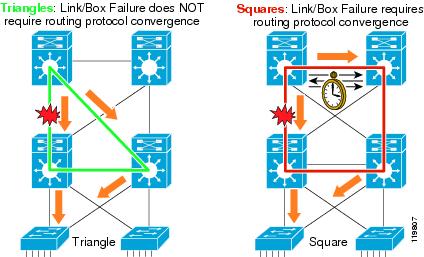
Redundant Triangles
The multilayer switches are connected redundantly with a triangle of links that have Layer 3 equal costs. Because the links have equal costs, they appear in the routing table (and by default will be used for load balancing). If one of the links or distribution layer devices fails, convergence is extremely fast, because the failure is detected in hardware and there is no need for the routing protocol to recalculate a new path; it just continues to use one of the paths already in its routing table.
Redundant Squares
In contrast, only one path is active by default, and link or device failure requires the routing protocol to recalculate a new route to converge.
General Guidance:
- Consider default gateway redundancy (where applicable) using dual connections to redundant distribution layer switches that use VRRP/HSRP/GLBP such that it provides fast failover from one switch to the other at the distribution layer
- Link Aggregation (Ether-Channel or 802.3ad) between switches And/Or switch stacks which provide higher effective bandwidth while reducing complexity and improving service availability
- Deploy redundant triangles as opposed to redundant squares
- Deploy redundant distribution layer switches (preferably stacked together)
- Deploy redundant point-to-point L3 interconnections in the core
- High availability in the distribution layer should be provided through dual equal-cost paths from the distribution layer to the core and from the access layer to the distribution layer. This results in fast, deterministic convergence in the event of a link or node failure
- Redundant power supplies to enhance the overall service availability
- High availability in the distribution layer is achieved through dual equal-cost paths from the distribution layer to the core and from the access layer to the distribution layer. (This results in fast, deterministic convergence in the event of a link or node failure).
The following Meraki MS platforms support Power Supply resiliency:
- MS250
- MS350
- MS355
- MS390
- MS420
- MS425
Meraki MS390 switches support StackPower in addition to Power resiliency and are in combined power mode by default
Firmware
General Guidance
- It’s always important to consider the topology of your switches as, when you drive closer to the network core and away from the access layer, the risk during a firmware upgrade increases
- For Large Campus LAN, it is recommended to start the upgrade closest to the access layer
- For Core switches, it is recommended to reschedule the upgrade to your desired maintenance window
- Staged Upgrades allows you to upgrade in logical increments (For instance, starting from low-risk locations at the access layer and moving onto the higher risk core)
- Firmware for MS switches is set on the network level and therefore all switches in that network will have the same firmware
- Major releases; A new major firmware is released with the launch of new products, technologies and/or major features. New major firmware may also include additional performance, security and/or stability enhancements
- Minor releases; A new minor firmware version is released to fix any bugs or security vulnerabilities encountered during the lifecycle of a major firmware release
- On average, Meraki deploys a new firmware version once a quarter for each product family
- Please plan for sufficient bandwidth to be available for firmware downloads as they can be large in size
- It is recommended to set the out-of-hours preferred upgrade date and time in your network settings for automatic upgrades (remember to set the network's timezone)
- You can also manually upgrade network firmware from Organization > Firmware Upgrades (Meraki will notify you 2 weeks in advance of the scheduled upgrade and, within this two week time window, you have the ability to reschedule to a day and time of your choice)
- Meraki MS devices use a “safe configuration” mechanism, which allows them to revert to the last good (“safe”) configuration in the event that a configuration change causes the device to go offline or reboot.
- During routine operation, if a device remains functional for a certain amount of time (30 minutes in most circumstances, or 2 hours on the MS after a firmware upgrade), a configuration is deemed safe
- When a device comes online for the first time or immediately after a factory reset, a new safe configuration file is generated since one doesn’t exist previously
- It is recommended to leave the device online for 2 hours for the configuration to be marked safe after the first boot or a factory reset.
Multiple reboots in quick succession during initial bootup may result in a loss of this configuration and failure to come online. In such events, a factory reset will be required to recover
General Recommendation
When upgrading Meraki switches it is important that you allocate enough time in your upgrade window for each group or phase to ensure a smooth transition. Each upgrade cycle needs enough time to download the new version to the switches, perform the upgrade, allow the network to reconverge around protocols such as spanning tree and OSPF that may be configured in your network, and some extra time to potentially roll back if any issue is uncovered after the upgrade.
Meraki firmware release cycle consists of three stages during the firmware rollout process namely beta, release candidate (RC) and stable firmware. This cycle is covered in more detail in the Meraki Firmware Development Lifecycle section.
Please note that Meraki beta is fully supported by Meraki Technical Support and can be considered as an Early Field Deployment release. If you have any issues with the new beta firmware you can always roll back to the previous stable version, or the previously installed version if you roll back within 14 days
The high-level process for a switch upgrade involves the following:
-
The switch downloads the new firmware (time varies depending on your connection)
-
The switch starts a countdown of 20 minutes to allow any other switches downstream to finish their download
-
The switch reboots with its new firmware (about a minute)
-
Network protocols re-converge (varies depending on configuration)
Meraki Firmware Version Status will show with one of the following options:
Each firmware version now has an additional Status column as follows:
- Good (Green) status indicates that your network is set to the latest firmware release. Minor updates may be available, but no immediate action is required.
-
Warning (Yellow) status means that a newer stable major firmware or newer minor beta firmware is available that may contain security fixes, new features, and performance improvements. We recommend that you upgrade to the latest stable or beta firmware version.
-
Critical (Red) status indicates that the firmware for your network is out of date and may have security vulnerabilities and/or experience suboptimal performance. We highly recommend that you upgrade to the latest stable and latest beta firmware release.
For more information about Firmware Upgrades, please refer to the following FAQ document.
MS390 Specific Guidance
- Meraki continues to develop software capabilities for the MS390 platform, therefore it is important to refer to the firmware changelog before setting a firmware for your network which includes MS390 switches.
- Please ensure that the firmware selected includes support for MS390 build.
- Also pay attention to the new features section as well as the known issues related to this firmware.
Staged Upgrades Guidance
- To make managing complex switched networks simpler, Meraki supports automatic staged firmware updates
- This allows you to easily designate groups of switches into different upgrade stages
- When you are scheduling your upgrades you can easily mark multiple stages of upgrades (e.g. Stage1, Stage2 and Stage3)
- Each stage has to complete its upgrade process before proceeding to the next stage
- All members of a switch stack must be upgraded at the same time, within the same upgrade window.
- You cannot select an individual switch stack member to be upgraded; only the entire switch stack can be selected
- Switch stacks upgrade behavior; each stack member rebooting close to the same time and the stack then automatically re-forming as the members come online
This feature is currently not supported when using templates
Firmware Upgrade Barriers
- Firmware upgrade barriers is a built-in feature to prevent certain upgrade paths on devices running older firmware versions trying to upgrade to a build that would otherwise cause compatibility issues.
- Having devices use intermediary builds defined by Meraki will ensure a safe transition when upgrading your devices.
Here is an example of when firmware upgrade barriers come into effect. You might find yourself in a situation where you are unable to upgrade a device for an extended period of time due to uptime or business requirements. There is a switch in the network that is running MS 9.27 and would like to update to the latest stable version, which at the time of writing, is 11.30. Attempting to upgrade from 9.27 to 11.30 will not be a selectable option in the dashboard and administrators will have to upgrade to 10.35 first.
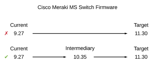
In order to complete the upgrade from the current version to the target version, two manual upgrades will be required. The first from your current to the intermediary version, and another from the intermediary to your target version.
Meraki Switches per Dashboard Network
General Guidance
- It is recommended to keep the total number of Meraki switches (e.g. Access AND Distribution) in a dashboard network within 400 for best performance of dashboard.
- If switch count exceeds 400 switches, it is likely to slow down the loading of the network topology/ switch ports page or result in display of inconsistent output.
- It is recommended to keep the total switch port count in a network to fewer than 8000 ports for reliable loading of the switch port page
There is no hard limit on the number of switches in a network, therefore please take this into consideration when you are planning for the whole Campus LAN network.
Cabling
General Guidance
- It is recommended to use Category-5e cables for switch ports up to 1Gbps
- While Category-5e cables can support multigigabit data rates upto 2.5/5 Gbps, external factors such as noise, alien crosstalk coupled with longer cable/cable bundle lengths can impede reliable link operation.
- Noise can originate from cable bundling, RFI, cable movement, lightning, power surges and other transient events.
- It is recommended to use Category-6a cabling for reliable multigigabit operations as it mitigates alien crosstalk by design
- Please ensure that you are using Approved Meraki SFPs and Accessories per hardware model
Meraki will only support the Approved Meraki SFPs and Accessories for use with MS and MX platforms. A number of Cisco converters have also been certified for use with Meraki MS switches:
- SFP-H10GB-CU1M
- SFP-H10GB-CU3M
- SFP-10G-SR-S
- SFP-10G-SR
Power Over Ethernet (PoE)
General Guidance
- MS platforms allocate power based on the actual drawn power from the client device
MS390 Specific Guidance
- MS390s allocate power based on the requested power from the client device (as opposed to the actual drawn power).
- It is recommended to calculate your power budget based on the maximum power mentioned on the client device data sheet (e.g. MR56 consumes 30W).
- This is based on the power class advertised using Layer 2 discovery protocols (e.g. LLDP, CDP). Refer to the following table for more information on the power class and the corresponding power values:
| Class | Maximum Power Level |
|---|---|
| 0 (unknown class) | 15.4 W |
| 1 | 4 W |
| 2 | 7 W |
| 3 | 15.4 W |
| 4 | 30 W |
| 5 | 45 W |
| 6 | 60 W |
| 7 | 75 W |
| 8 | 90 W |
IP Addressing and VLANs
General Guidance
- All Meraki MS platforms switchports are configured in Trunk mode with Native VLAN 1 by default with Management VLAN 1
- Even if it is undesirable to use Native VLAN 1, it is recommended to use it for provisioning the switches for ZTP purposes. Once the switches/stacks are online on dashboard in running steady, you can then change the Management VLAN as required. Remember to change port settings downstream first to avoid losing access to switches.
- Assign a dedicated management VLAN for your switches which has access to the Internet (More info here)
- Avoid overlapping subnets as this may lead to inconsistent routing and forwarding
- Dedicate /24 or /23 subnets for end-user access
- Do not configure a L3 interface for the management VLAN. Use L3 interfaces only for data VLANs. This helps in separating management traffic from end-user data
All MS platforms (excluding MS390) use a separate routing table for management traffic. Configuring a Management IP within the range of a configured SVI interface can lead to undesired behavior. The Management VLAN must be separate from any configured SVI interface.
- Unrequired VLANs should be manually pruned from trunked interfaces to avoid broadcast propagation.
- If you require that your Radius, Syslog or SNMP traffic to be encapsulated in a separate VLAN (that is not necessarily exposed to the internet) then consider using the Alternate Management Interface on MS. Please refer to the table below for this feature compatibility:
| MS Switch Family | MS Switch Model | MS Firmware Support (first supported on) |
| MS2xx | MS210 | MS14.5 |
| MS225 | MS14.5 | |
| MS250 | MS14.5 | |
| MS3xx | MS350 | MS14.5 |
| MS355 | MS14.5 | |
| MS390 | MS15 | |
| MS4xx | MS410 | MS14.5 |
| MS425 | MS14.5 | |
| MS450 | MS14.5 |
The Alternate Management Interface (AMI) functionality is enabled at a per-network level and, therefore, all switches within the Dashboard Network will use the same VLAN for the AMI. The AMI IP address can be configured per switch statically as shown below:
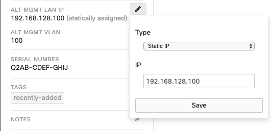
Please note that the subnet of the AMI (the subnet mask for the AMI IP address) is derived from Layer-3 interface for the AMI VLAN, if one has been configured on the switch. In the absence of a Layer-3 interface for the AMI VLAN, each switch will consider its AMI to be /32 network address
Layer 3 routing must be enabled on a switch for its AMI to be activated
MS390 Specific Guidance
- The default active VLANs on any MS390 port is 1-1000. This can be changed via local status page or in dashboard (See note below)
- Please ensure that the MS390 switch/stack has a maximum of 1000 VLANs
- The total number of VLANs supported on ANY MS390 switch port is 1000
For example, If you have an existing stack with each port set to Native VLAN 1, 1-1000 and the new member ports are set to native VLAN 1; allowed VLANs: 1,2001-2500 then your total number of VLAN in the stack will be 1000(1-1000)+500(2001-2500) = 1500. Dashboard will not allow the new member to be added to the stack and will show an error.
To utilize any VLANs outside of 1-1000 on an MS390, the switch or switch stack must have ALL of its trunk interfaces set to an allowed vlan list that contains a total that is less than or equal to 1000 VLANs, including any of the module interfaces that are not in use. Here's a quick way to do that.
MS390 Stacking Specific Guidance
- Please refer to the MS390 Stacking guidance provided below
DHCP
General Guidance
- DHCP is recommended for faster deployments and zero-touch
- It is recommended to fix the DHCP assignments on the DHCP server as this will ensure that other network applications (e.g. Radius) will always use the same source IP address range (i.e. the Management/AMI VLAN)
- Static IP addressing can also be used however to minimize initial provisioning it's recommended to use DHCP for initial setup, then change IP addressing from dashboard. Meraki MS switches will attempt to do DHCP discovery on all supported VLANs.
Please refer to the stacking section for further guidance on IP addressing when using switch stacks
MS390 Specific Guidance
- When installing an MS390, it is important to ensure that any DHCP services or IP address assignments used for management fall within the active VLAN range (1-1000 by default, unless changed via the local status page or dashboard)
- If you require using Static IP addressing (OR an IP Address outside of the default active VLANs 1-1000) please connect each MS390 switch with an uplink to the Meraki dashboard and upgrade firmware to latest stable prior to changing any configuration. Once the switch upgrades and reboots, you can now change the management IP as required (please ensure the upstream switch/device allows this VLAN in its port configuration).
MS390 Stacks Specific Guidance
- It is recommended to set the same IP address on all switches in dashboard once DHCP assigns IP addressing and the stack is online (e.g. dashboard shows that the management IP of the stack is 10.0.5.20, then please statically set this IP on all switch members of the stack)
- Thus, it is recommended to use Static IP address as opposed to DHCP. Please connect each MS390 switch with an uplink (do not connect any stacking cables at this stage) to dashboard and upgrade firmware to latest stable prior to changing any configuration. Once the switch upgrades and reboots, you can now change the management IP as required (please ensure the upstream switch/device allows this VLAN in its port configuration). Don't forget to assign the same IP address to all members of the stack. (Start with the primary switch, this should automatically assign the same IP to all members within the same stack)
MS390 Stack IP Address Provisioning Sequence for Best Results:
- Claim your MS390s into a dashboard network (do not create a stack)
- Set the firmware to 11.31+
- Connect an uplink to each switch (members un-stacked)
- Ensure that the stacking cables are not connected to any member
- Power on switches (members un-stacked)
- Have DHCP available on native VLAN 1
- Wait for firmware to be loaded and configuration to be synced
- Power off switches
- Disconnect all uplinks from all switches
- Connect stacking cables to all members to form a ring topology
- Connect one uplink to one member (only one link for the stack)
- Power on switches and wait for them to come online on dashboard
- Create a stack on dashboard by adding all members
- Wait for the stack ports to show online on all members in dashboard
- Observe the IP address used on the stack members (should be the same for all members)
- Click on the IP address of each switch and change settings from DHCP to Static. Configure the IP address that is used for the stack for each switch member
- Configure Link aggregation as needed and add more uplinks accordingly
- Make sure to abide to the maximum VLAN count as described in the below section when you provision your MS390 stack/switches
Please note that the Primary switch owns the Management IP and will resolve ARP requests to its own MAC address
Supported VLANs
General Guidance
- All MS platforms (except MS390): VLANs 1-4096 supported
- It is recommended to take some initiative in designing the campus to decrease the size of broadcast domains by limiting where VLANs traverse. This requires that your VLANs to be trunked to only certain floors of the building or even to only certain buildings depending on the physical environment. This reduces the flooding expanse of broadcast packets so that traffic doesn’t reach every corner of the network every time there’s a broadcast, reducing the potential impact of broadcast storms
Meraki MS platforms do not support the VTP Protocol
MS390 Specific Guidance
- MS390s support the following VLAN ranges: 1-1001 and 1006-4092 with a maximum VLAN count* of 1000
- MS390 has the following Default Active VLANs: VLAN ID 1-1000 (i.e. configured by default) However, the active VLANs can be changed via the local status page or dashboard (after the switch has come online)
The following VLAN ranges are reserved on MS390 switches: 1002-1005, 4093-4094
* MS390 switches support up to 1000 VLANs in total. It is recommended to configure the switch ports with the specific VLANs (or ranges) to stay within the 1000 VLAN count (e.g. 1-20, 100-300, 350, 900-1000, 1050-1250)
Please ensure that all trunk ports on MS390 switches are configured such that the maximum VLAN count is 1000. (i.e. Do not exceed the maximum VLAN count of 1000 on any switch port)
MS390 Stacks Specific Guidance
- Same guidance for MS390s
Spanning Tree Protocol & UDLD
General Guidance
- All Meraki MS switches (with the exception of MS390) support RSTP for loop prevention
- RSTP is enabled by default and should always be enabled. Disable only after careful consideration (Such as when the other side is not compatible with RSTP)
- MS switches will automatically place all access interfaces into EDGE mode. This will cause the interface to immediately transition the port into STP forwarding mode upon linkup (Please note that the port still participates in STP)
- Configure other switches in your network (where possible) in RSTP mode. Otherwise, please plan carefully for interoperability issues
You must set allow VLAN 1 on the trunk between MS switches and other switches as this is required for RSTP
- For a traditional multi-layer Campus LAN set the STP priority as follows:
- Core/Collapsed Core = 4096*
- Distribution = 16384
- Access = 61440
- Designate the switch with the minimal changes (configuration, links up/down, etc) as the root bridge
- Root bridge should be in your distribution/core layer
- STP priority on your root bridge should be set to 4096*
- Ideally, the switch designated as the root should be one which sees minimal changes (config changes, link up/downs etc.) during daily operation
- Enable BPDU Guard on all access ports (Including ports connected to MR30H/36H)
- Enable Root Guard on your distribution/core switches on ports facing your access switches
- Enable Loop Guard on trunk ports connecting switches within the same layer (e.g. Trunk between two access switches that are both uplinked to the distribution/core layer)
- It is also recommended that Loop Guard be paired with Unidirectional Link Detection (UDLD)
- Keep your STP domain diameter to 7 hops as maximum
- With each hop, increase your STP priority such that it is less preferred than the previous-hop
- If you are running a routed access layer, it is recommended to set the uplink ports as access and keep STP enabled as a failsafe
- It is recommended to couple STP with UDLD
- Remember that UDLD must be supported and enabled on both ends
- UDLD is supported on the following MS platforms: MS22, MS42, MS120, MS125, MS210, MS220, MS225, MS250, MS320, MS350, MS355, MS390 (Running MS15.3 and above), MS400 series (Running MS10.10 and above)
- UDLD is run independently on a per-switch basis, regardless of any stacking involved
- The Meraki implementation is fully interoperable with the one implemented in traditional Cisco switches
- UDLD can either be configured in Alert only or Enforce
- UDLD is fully compatible with Cisco switches (more info here)
- It is also recommended that Loop Guard be paired with Unidirectional Link Detection
* While it is acceptable to set the STP priority on the root bridge to 0, it allows for no room for modification when replacing a switch or changing the topology temporarily. Thus, setting it to 4096 gives you that flexibility
MS390 Specific Guidance
- MS390s support MST in instance 0 / region 1 / revision 1
- MST is enabled by default and should always be enabled. Disable only after careful consideration (Such as when the other side is not compatible with MST)
- MS90 switches with 12.28.1+ supports portfast
- Please ensure that other switches in the STP domain are configured with MST (where possible) or alternatively with RSTP since it's backward compatible.
- It's required to have the same native VLAN configured for all switches in a STP domain as a switch will only send (or listen to) backward compatible BPDUs (e.g. PVST, PVST+) on its native VLAN (which is VLAN 1 by default). More information about Hybrid LAN in the below section.
- For a traditional multi-layer Campus LAN set the STP priority as follows:
- Core/Collapsed Core = 4096*
- Distribution = 16384
- Access = 61440
- All access ports on MS390 running 12.28 and higher will have Portfast enabled by default
- Designate the switch with the minimal changes (configuration, links up/down, etc) as the root bridge
- Root bridge should be in your distribution/core layer
- STP priority on your root bridge should be set to 4096*
- Ideally, the switch designated as the root should be one which sees minimal changes (config changes, link up/downs etc.) during daily operation
- Enable BPDU Guard on all access ports (Including ports connected to MR30H/36H)
- Enable Root Guard on your distribution/core switches on ports facing your access switches
- Enable Loop Guard on trunk ports connecting switches within the same layer (e.g. Trunk between two access switches that are both uplinked to the distribution/core layer)
- It is also recommended that Loop Guard be paired with Unidirectional Link Detection (UDLD)
- Keep your STP domain diameter to 7 hops as maximum
- With each hop, increase your STP priority such that it is less preferred than the previous hop
- It is recommended to couple STP with UDLD
- Remember that UDLD must be supported and enabled on both ends
- UDLD is supported on MS390 with firmware 15.3 and above (Please check firmware changelog for more info)
- UDLD is run independently on a per-switch basis, regardless of any stacking involved
- The Meraki implementation is fully interoperable with the one implemented in traditional Cisco switches
- UDLD can either be configured in Alert only or Enforce
- UDLD is fully compatible with Cisco switches (more info here)
- It is also recommended that Loop Guard be paired with Unidirectional Link Detection
* While it is acceptable to set the STP priority on the root bridge to 0, it allows for no room for modification when replacing a switch or changing the topology temporarily. Thus, setting it to 4096 gives you that flexibility
Further Guidance on Cisco interoperability and UDLD
-
Traditional Cisco equipment supports 'aggressive' and 'normal' UDLD modes. Meraki is able to implement similar functionality using just the 'normal' mode
-
In Alert only mode, the Meraki implementation generates a Dashboard alert and Event Log entry. Traffic is still forwarded when a UDLD-error state is seen while configured in Alert only mode
-
In Enforce mode, Meraki behavior is mostly comparable to Cisco's aggressive mode. Similar to 'disabling' the port, Meraki blocks all traffic, similar to the STP blocking state. This does not physically bring the link down, though, as in a traditional Cisco 'aggressive' configuration
STP in a Hybrid LAN
A hybrid LAN is a Wired LAN which consists of multi-vendor platforms. In many cases, each vendor has its own implementation of the STP protocol. In fact, some vendors will even slightly deviate from the protocol standard.
Since STP is all about preventing network loops and electing a root bridge by exchanging BPDUs across the network, it is vital that this process does not get interrupted across the different platforms in a hybrid environment. For instance, if a bridge is sending out BPDUs in a VLAN that is not allowed on the trunk connecting between the two bridges it may very well lead to a problem.
As such, it is very important to understand how STP operates on each switch and revise the vendor's documentation to understand the specifics of STP.
Meraki MS (except MS390) supports standard based 802.1W RSTP
Meraki MS390 supports standard based 802.1S MSTP in a single instance (Instance 0)
General Guidance for STP in a Hybrid LAN
- Please ensure that all your VLANs in your PVST+/Rapid-PVST domain are running STP
- All these VLANs should be allowed on all trunks
- Ensure that all VLANs have the same root bridge
- When using PVST/PVST+, ensure that the root bridge is in the Presides on a PVST switch
- Consider using Native VLAN 1 on all switches for the best results (Otherwise ensure Native VLAN consistency everywhere in your STP domain)
- When adding VLANs, be wary of the order of change that might push some ports into inconsistent state. As a rule of thumb, start from Core working your way downstream
- Do not leave your PVST+/Rapid-PVST Bridge priority to their default values and ensure consistency of the root location across all VLANs
- Bridge Priority 4096 can facilitate a root migration as opposed to priority 0
- With each switch hop increase the STP priority to be higher than last hop
- Where possible, avoid using default priority 32768
- Use STP guard Root Guard to protect your Root
- Use STP guard BPDU Guard to protect your STP domain from the access edge
- It is highly recommended to run MSTP in a Hybrid LAN where possible as this will reduce misconfiguration and eliminate chances of falling back to legacy STP (802.1D)
The following table provides some further guidelines on STP interoperability in a hybrid LAN network. Please follow the recommended design options and/or the guidance provided based on your specific implementation.
It is highly recommended to run the same STP protocol across all switches in your network where possible. The below design guidelines can help you to achieve better integration and performance results where running the same protocol is not possible however it requires that you understand the caveats and implications of each of the design options
| Non Meraki Switches | All MS Platforms (Except MS390) - 802.1W RSTP | MS390 - 802.1S MSTP (Instance 0 / Region 1 / Revision 1) |
|---|---|---|
| STP |
Not Recommended Option |
Not Recommended Option |
| RSTP |
Recommended Option Behavior:
Guidelines:
conf t rstp single end |
Recommended Option Behavior:
Guidelines:
conf t rstp single end |
| PVST/PVST+ |
Not Recommended Option Behavior:
Guidelines:
To avoid any issues with STP, it is recommended to convert the Cisco Catalyst environment to single instance MSTP. This will ensure maximum compatibility in the STP environment. |
Not Recommended Option Behavior:
Guidelines:
If you choose to configure a native VLAN other than VLAN 1, please be wary of the order of change on your switches as this might cause the MS390 to go offline (e.g. WAN Edge - PVST+(a) - MS390 - PVST+(b), changing the native VLAN on PVST+(b) first can cause the MS390 to go offline) To avoid any issues with STP, it is recommended to convert the Cisco Catalyst environment to single instance MSTP. This will ensure maximum compatibility in the STP environment. Don't forget to configure your non-MS390 switches with the correct MSTP settings:
spanning-tree mode mst
spanning-tree mst configuration
name region1
revision 1
spanning-tree mst 0 priority {stp priority value}
It might be required to bounce ports on the non-MS390 switches after migrating to MSTP to ensure that the port type is correct (P2p) |
| Rapid-PVST |
Not Recommended Option Behavior:
Guidelines:
conf t
rstp single
end
To avoid any issues with STP, it is recommended to convert the Cisco Catalyst environment to single instance MSTP. This will ensure maximum compatibility in the STP environment. |
Recommended Option Behavior:
Guidelines:
To avoid any issues with STP, it is recommended to convert the Cisco Catalyst environment to single instance MSTP. This will ensure maximum compatibility in the STP environment. |
| MSTP |
Recommended Option Behavior:
Guidelines:
|
BEST Recommended Option Behavior:
Guidelines:
spanning-tree mode mst
spanning-tree mst configuration
name region1
revision 1
spanning-tree mst 0 priority {stp priority value}
|
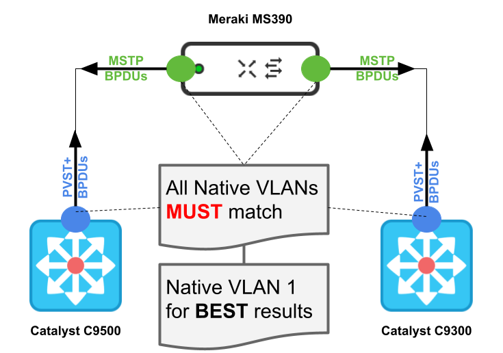.png?revision=1)
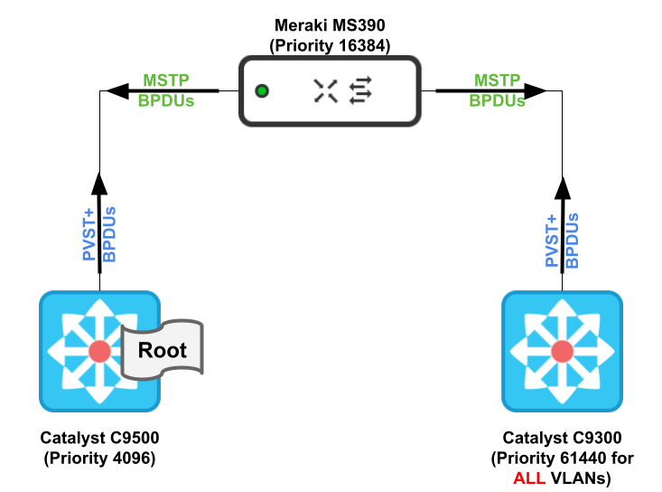_(1).png?revision=1)
To illustrate the behavior of the different switching platforms in a Hybrid STP domain, please refer to the following diagram which explains for a given topology the operational behavior and the considerations that need to be taken into account when designing your STP domain.
The below diagram by no means should be considered as a recommended STP design but rather it is there to help you understand the interoperability considerations between the different platforms when running different STP protocols.
.png?revision=1)
Physical Stacking - General
Migrating to a switch stack is an effective, flexible, and scalable solution to expand network capacity:
Benefits:
- Physical stacking will provide a high-performance and redundant access layer
- Physical stacking can also provide the network with ample bandwidth for an enterprise deployment
- Multiple uplinks can be used with cross-stack link aggregation to achieve more throughput to aggregation or core layers
- The switch stack behaves as a single device (characteristics and functionality of a single switch)
- The switch stack allows expansion of switch ports without having to manage multiple devices
- Switches can be added or removed from the switch stack without affecting the overall operation of the switch stack
General Guidance
- Create a full ring topology (i.e. stacking port 1 / switch 1 to stacking port 2 / switch 2, stacking port 1 / switch 2 to stacking port 2 / switch 3, etc)
- Finish your full ring topology by connecting stacking port 1 / switch x to stacking port 2 on switch 1)
- Use distributed uplinks across the stack such that they are equidistant (e.g. distance between uplinks is 2 hops). This will ensure that there are minimal hops across the stack for traffic to get to an uplink.
- Where applicable, use cross-stack link aggregation to increase your uplink capacity from access to distribution
Please refer to the below diagram for recommendations on stack uplinks:
.png?revision=1)
For selected models, it is possible to stack different switch models together. Please refer to this document for more information on the supported platforms
In case of switch stacks, ensure that the management IP subnet does not overlap with the subnet of any configured L3 interface. Overlapping subnets on the management IP and L3 interfaces can result in packet loss when pinging or polling (via SNMP) the management IP of stack members. NOTE: This limitation does not apply to the MS390 series switches.
MS switches support one-to-one or many-to-one mirror sessions. Cross-stack port mirroring is available on Meraki stackable switches. Only one active destination port can be configured per switch/stack
Physical Stacking - All models except MS390/420/425
General Guidance
- Add the switch(s) to a dashboard network (Assuming they have already been claimed to your dashboard account)
- Power on each switch
- Connect a functional uplink to each switch such that it can access the Meraki Cloud (Please note that switches will use Management VLAN 1 by default so make sure the upstream device is configured accordingly)
- Set the firmware level for your switches from Organization > Firmware Upgrades (Consult the firmware changelog to choose the latest stable vs beta firmware)
- Wait until all your switches download firmware and come back online with the new firmware
- Power off all switches
- Disconnect uplink cables from all switches
- Connect the stacking cables to create a full ring topology
- Connect one uplink for the entire stack (Choose one of the ports used previously but only one port with one uplink for the entire stack)
- Power on each switch
- Wait for all switches to come online in dashboard and show the same firmware on the switch page
- Enable stacking on dashboard (Please note that dashboard might auto detect the stack and show it under Detected potential stacks)
- Provision the stack as required (either via Detected potential stacks or by manually selecting the switches and adding them into a stack)
- Where applicable, configure link aggregation to add more uplinks and connect the uplink cables to the designated ports on the selected switches
If required, IP addressing can be changed to different settings (e.g. Static IP address or a different management VLAN) after the stack has been properly configured and is showing online on dashboard
If the network is bound to a template, please follow the instructions here instead.
If you face problems with stacking switches, please check the common alerts here.
Adding a new switch(s) to an existing MS Switch Stack (all supported models except MS390/420/425)
- Add the switch(s) to the same dashboard network (Assuming they have already been claimed to your dashboard account)
- Power on each switch
- Connect a functional uplink to each switch such that it can access the Meraki Cloud (Please note that switches will use Management VLAN 1 by default so make sure the upstream device is configured accordingly)
- Wait until all your switches download firmware and come back online with the new firmware
- Power off all new switches
- Disconnect uplink cables from all switches
- Disconnect the stacking cable from stacking port 2 / switch 1 (keep it connected on the other end)
- Now connect the stacking cable to stacking port 2 / new switch (i.e. Have the last stack member connect to port 2 on the new switch)
- Connect the new members with stacking cables and ensure that you create a full ring topology (stacking port 1 / last switch to stacking port 2 / first switch)
- Power on the new switch(s)
- Wait for all new switches to come online in dashboard and show the same firmware on the switch page
- From Switch > Switch stacks choose your stack and click Manage members
- Provision the stack as required (by manually selecting the new switches and adding them into the existing stack)
- Where applicable, configure link aggregation to add more uplinks and connect the uplink cables to the designated ports on the selected switches
If the network is bound to a template, please follow the instructions here instead.
If you face problems with stacking switches, please check the common alerts here.
Physical Stacking - MS390
General Guidance
Do not stack more than 8 MS390 switches together. To install stacking cables; align the connector and connect the stack cable to the stack port on the switch back panel and finger-tighten the screws (clockwise direction).
- Add the switch(s) to a dashboard network (Assuming they have already been claimed to your dashboard account)
- Power on each new switch simultaneously
- Connect a functional uplink to each new switch such that it can access the Meraki Cloud (Please note that switches will use Management VLAN 1 by default so make sure the upstream device is configured accordingly)
- Set the firmware level for your switches from Organization > Firmware Upgrades (Consult the firmware changelog to choose the latest stable vs beta firmware, and make sure it supports the MS390 build)
- Wait until all your switches download firmware and come back online with the new firmware (this might take up to an hour)
- Navigate to Switch > Switch stacks
- Click Add one
- Select the switches to be added to the stack and click Create
- Power off all switches
- Disconnect uplink cables from all switches
- Connect the stacking cables to create a full ring topology (ensure that each connector is correctly aligned to the switch's stacking port it is connecting to and finger-tighten the screws in clockwise direction. Make sure the Cisco logo is on the top side of the connector) See below picture as an illustration; Green indicates correct insertion, Red indicates wrong insertion:
- Connect one uplink for the entire stack (Choose one of the ports used previously but only one port with one uplink for the entire stack)
- Power on each switch
- Wait for all switches to come online in dashboard and show the same firmware on the switch page
- Enable stacking on dashboard (Please note that dashboard might auto detect the stack and show it under Detected potential stacks)
- Provision the stack as required (either via Detected potential stacks or by manually selecting the switches and adding them into a stack)
- Where applicable, configure link aggregation to add more uplinks and connect the uplink cables to the designated ports on the selected switches
Please note that all MS390 switches in a stack will show the same management IP address as there is only one control plane running on the primary switch. It is recommended to configure the same IP address on all switches to ensure that traffic uses the same IP during failover scenarios
If required, IP addressing can be changed to different settings (e.g. Static IP address or a different management VLAN) on all stack members after the stack has been properly configured and is showing online on dashboard. Again, it is recommended to configure the same IP address on all switches to ensure that traffic uses the same IP during failover scenarios
If a member needs to be removed from a stack, please amend to its unique IP address details before removing it from the stack.
Rebooting a member from dashboard (or by power recycle) will reboot all members in a stack.
Factory resetting a member will reboot all members in a stack
If you have already configured settings in your dashboard network with port settings etc, please ensure that the switch/stack has a maximum of 1000 VLANs. For example, If you have an existing stack with each port set to Native VLAN 1, 1-1000 and the new member ports are set to native VLAN 1; allowed VLANs: 1,2001-2500 then your total number of VLAN in the stack will be 1000(1-1000)+500(2001-2500) = 1500. Dashboard will not allow the new member to be added to the stack and will show an error
If the network is bound to a template, please follow the instructions here instead.
If you face problems with stacking switches, please check the common alerts here.
MS390 Stack IP Address Provisioning Sequence for Best Results:
- Claim your MS390s into a dashboard network (do not create a stack)
- Set the firmware to 11.31+
- Connect an uplink to each switch (members un-stacked)
- Ensure that the stacking cables are not connected to any member
- Power on switches (members un-stacked)
- Have DHCP available on native VLAN 1
- Wait for firmware to be loaded and configuration to be synced
- Power off switches
- Disconnect all uplinks from all switches
- Connect stacking cables to all members to form a ring topology
- Connect one uplink to one member (only one link for the stack)
- Power on switches and wait for them to come online on dashboard
- Create a stack on dashboard by adding all members
- Wait for the stack ports to show online on all members in dashboard
- Observe the IP address used on the stack members (should be the same for all members)
- Click on the IP address of each switch and change settings from DHCP to Static. Configure the IP address that is used for the stack for each switch member
- Configure Link aggregation as needed and add more uplinks accordingly
- Make sure to abide to the maximum VLAN count as described in the above section when you provision your MS390 stack/switches
Please note that the Primary switch owns the Management IP and will resolve ARP requests to its own MAC address
Adding a new MS390 switch(s) to an existing MS390 Switch Stack
- Add the switch(s) to the same dashboard network (Assuming they have already been claimed to your dashboard account)
- Power on each new switch
- Connect a functional uplink to each new switch such that it can access the Meraki Cloud (Please note that switches will use Management VLAN 1 by default so make sure the upstream device is configured accordingly)
- Wait until all your switches download firmware and come back online with the new firmware
- From Switch > Switch stacks choose your stack and click Manage members
- Provision the stack as required (by manually selecting the new switches and adding them into the existing stack)
- Power off all new switches
- Disconnect uplink cables from all switches
- Disconnect the stacking cable from stacking port 2 / switch 1 (keep it connected on the other end)
- Now connect the stacking cable to stacking port 2 / new switch (i.e. Have the last stack member connect to port 2 on the new switch)
- Connect the new members with stacking cables and ensure that you create a full ring topology (stacking port 1 / last switch to stacking port 2 / first switch)
- Power on the new switch(s)
- Wait for all new switches to come online in dashboard and show the same firmware on the switch page
- Where applicable, configure link aggregation to add more uplinks and connect the uplink cables to the designated ports on the selected switches
If you have already configured settings in your dashboard network with port settings etc, please ensure that the switch/stack has a maximum of 1000 VLANs. For example, If you have an existing stack with each port set to Native VLAN 1, 1-1000 and the new member ports are set to native VLAN 1; allowed VLANs: 1,2001-2500 then your total number of VLAN in the stack will be 1000(1-1000)+500(2001-2500) = 1500. Dashboard will not allow the new member to be added to the stack and will show an error
If the network is bound to a template, please follow the instructions here instead.
If you face problems with stacking switches, please check the common alerts here.
StackPower for MS390
StackPower is an innovative feature that aggregates all the available power in a stack of switches and manages it as one common power pool for the entire stack. StackPower feature is introduced for the first time ever in Meraki Switching portfolio with the MS390s.
By pooling & distributing power across MS390s using a series of StackPower cables, StackPower provides simple and resilient power distribution across the stack. Below is the back panel of MS390 depicting the location of StackPower ports.
Guidance and steps to deploy StackPower:
- StackPower is only supported on MS390s with MS15+
- Do not add more than 4 x MS390 switches in power-stack
- If need be, split your MS390 switches into two power-stack units within a single Data stack (For instance, if you have a total of 5 MS390 switches in a data-stack, you can configure 3 switches in one power-stack setup and the rest 2 switches in another power-stack setup as shown below)
- Connect the end of the cable with a green band to either StackPower port on the first switch
- Align the connector correctly, and insert it into a StackPower port on the switch rear panel.
- Connect the end of the cable with the yellow band to another switch
- Hand-tighten the captive screws to secure the StackPower cable connectors in place.
- StackPower feature doesn't need any dashboard configuration but is automatically enabled when the cables are installed
If after connecting the cables you do not see the power-stack in dashboard, please contact Meraki support for further troubleshooting
Physical Stacking - MS420/425
General Guidance
Please note that 10 Gb/s is the minimum speed required to support flexible stacking.
Please use identical ports on both ends for stacking ports (e.g. both 10Gbps SFP+ or 40Gbps QSFP)
- Add the switch(s) to a dashboard network (Assuming they have already been claimed to your dashboard account)
- Connect an uplink to all your switch(s) such that it can access the Meraki Cloud (Please note that switches will use Management VLAN 1 by default so make sure the upstream device is configured accordingly)
- Please ensure that your uplink port is different from the intended stacking ports
- Set the firmware level for your switches from Organization > Firmware Upgrades (Consult the firmware changelog to choose the latest stable vs beta firmware)
- Power on each switch
- Wait until all your switches download firmware and come back online with the new firmware
- Configure the designated stacking port with the stacking enabled
- Connect the stacking cables to create a full ring topology
- Connect one uplink (or link aggregate) for the entire stack and remove all other uplinks
- Enable stacking on dashboard (Please note that dashboard might auto detect the stack and show it under Detected potential stacks)
- Provision the stack as required (either via Detected potential stacks or by manually selecting the switches and adding them into a stack)
- Where applicable, configure link aggregation to add more uplinks and connect the uplink cables to the designated ports on the selected switches
Converting a link aggregate to a stacking port is not a supported configuration and may result in unexpected behavior.
If the network is bound to a template, please follow the instructions here instead.
If you face problems with stacking switches, please check the common alerts here.
Physical Stacking - Replacing a Stack Member
Replacing a stack member can be useful in one of these occasions:
- A failed switch that is RMA'd and needs to be replaced with a new one (like for like)
- A switch that is being migrated to another switch (e.g. larger switch, PoE enabled, etc)
General Guidance
- Power off the stack member to be replaced
- Claim the new/replacement switch in the inventory
- Add the switch to the network containing the stack
- Edit the name of the switch if required (For instance, to resemble the old switch e.g. SW-SFO-#5-02)
- Power on the switch that is replacing the old one
- Connect a functional uplink to one of the ports on the switch
- Wait for the switch to come online and update its firmware to the one configured on your network (Refer to Organization > Firmware Upgrades and check the Switch details page)
- Navigate to Switch > Switch stacks
- Select the existing stack
- Navigate to the failed switch that is RMA'd and needs to be replaced with a new one (like for like)
- Follow one of the following options:
- To RMA a switch: Select the old switch (the one being replaced) and the new switch (that one replacing the old switch) and click clone switch
- To replace a member with a new switch: Instead, click on Manage members and select the new switch and add it to the stack (The new switch can then be configured as part of the stack with the desired configuration)
- Physically swap the switches
- Remove the old switch from the stack
- Remove the old switch from the network
After the switch has been added to the network and before it is added to the stack or replaced, it should be brought online individually and updated to the same firmware build as the rest of the stack. Failing to do so can prevent the switch from stacking successfully. The configured firmware build for the network can be verified under Organization > Firmware Upgrades. A flashing white or green LED on the status light on the switch indicates that a firmware upgrade is in progress.
If the network is bound to a template, please follow the instructions here instead.
If you face problems with stacking switches, please check the common alerts here.
Physical Stacking - Cloning a stack member
Cloning a stack member can be useful in one of these occasions:
- An identical switch is being added to the network and configuration needs to be cloned from an existing member in one of your stacks
- A failed switch that is RMA'd and needs to be replaced with a new one (like for like) but needs to be operational before the replacement occurs
General Guidance
- Claim the new/replacement switch in the inventory
- Add the switch to the network containing the stack
- Edit the name of the switch if required (For instance, to resemble the old switch e.g. SW-SFO-#5-02)
- Navigate to Switch > Switches
- Select the new/replacement switch and click on Edit > Clone
- Choose the switch that you want to clone the config from
- Click clone
- Power on the switch that is replacing the old one
- Connect a functional uplink to one of the ports on the switch
- Wait for the switch to come online and update its firmware to the one configured on your network (Refer to Organization > Firmware Upgrades and check the Switch details page)
- Navigate to Switch > Switch stacks
- Select the existing stack
- Navigate to Manage members and add the new switch
- Physically swap the switches
- Remove the old switch from the stack
- Remove the old switch from the network
If the network is bound to a template, please follow the instructions here instead.
If you face problems with stacking switches, please check the common alerts here.
Layer 2 Loop-Free Topology
Introduction
Layer 2 loop-free topology and the possibility of enabling Layer 3 on the access switches is an emerging design blueprint due to the following reasons:
- Better convergence results than designs that rely on STP to resolve convergence events
- A routing protocol can even achieve better convergence results than the time-tested L2/L3 boundary hierarchical design
- Convergence based on the up or down state of a point-to-point physical link is faster than timer-based non-deterministic* convergence
- The default gateway is at the Access switch/stack, and a first-hop redundancy protocol is not needed
- Instead of indirect neighbour or route loss detection using hellos and dead timers, physical link loss indicates that a path is unusable; all traffic is rerouted to the alternative equal-cost path
- Using all links from access to core (no STP blocking) thanks to ECMP
* Non-deterministic means that the path of execution isn't fully determined by the specification of the computation, so the same input can produce different outcomes, while deterministic execution is guaranteed to be the same, given the same input
Please check the following diagrams for better understanding the benefits of layer 2 loop-free topology:
Option 1: Gateway Redundancy Protocol (e.g. VRRP) Model
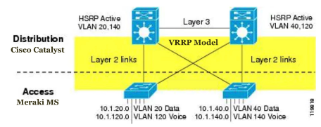
Per the above diagram, L2 links are deployed between the access and distribution nodes. However, no VLAN exists across multiple access layer switches. Additionally, the distribution-to-distribution link is an L3 routed link. This results in an L2 loop-free topology in which both uplinks from the Access layer are forwarding from an L2 perspective and are available for immediate use in the event of a link or node failure. This architecture is ideal for multiple buildings that are linked via fiber connections
In a less-than-optimal design where VLANs span multiple Building Access layer switches, the Building Distribution switches must be linked by a Layer 2 connection. That extends the layer 2 domain from the access layer to the distribution layer. Also, set your STP root and primary gateway on the same Distribution switch
Option 2: Dynamic Routing Protocol (e.g. OSPF) Model
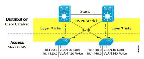
Per the above diagram, L3 links are deployed between the access and distribution nodes using Transit VLANs and SVIs are hosted on the Access Switches. Nonetheless, Etherchannels are used between Access and Distribution Stacks. This results in an L2 loop-free topology in which both uplinks from the Access layer are forwarding from an L2 perspective and are available for immediate use in the event of a link or node failure. This architecture is ideal for a single building where the distribution switches are stacked together in the same rack/cabinet
As seen with the above two options, you can achieve a layer 2 loop free topology. However, Please note that some additional complexity (uplink IP addressing and subnetting) and loss of flexibility are associated with this design alternative.
Now compare that to a Layer 2 looped topology as shown in the following diagram:
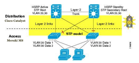
As you can see, some L2 links are blocked because of the loop prevention mechanism that is being used (i.e. STP). You must make sure that the STP root and default gateway (HSRP or VRRP) match. STP/RSTP convergence is required for several convergence events. Depending on the version of STP, convergence could take as long as 90 seconds.
General Guidance
- Localize your VLANs to an access switch/stack where possible (Mapping your broadcast domain to your physical space can be beneficial for more than one reason)
- There are many reasons why STP/RSTP convergence should be avoided for the most deterministic* and highly available network topology
- In general, when you avoid STP/RSTP, convergence can be predictable, bounded, and reliably tuned
- L2 environments fail open, forwarding traffic with unknown destinations on all ports and causing potential broadcast storms
-
L3 environments fail closed, dropping routing neighbor relationships, breaking connectivity, and isolating the soft failed devices
-
If you are running a routed access layer, it is recommended to set the uplink ports as access and keep STP enabled as a failsafe
-
If you're running routed distribution layer, it is recommended to summarize routes to the core (where applicable)
* Non-deterministic means that the path of execution isn't fully determined by the specification of the computation, so the same input can produce different outcomes, while deterministic execution is guaranteed to be the same, given the same input
Layer 3 Features
L3 configuration changes on MS210, MS225, MS250, MS350, MS355, MS410, MS425, MS450 require the flushing and rebuilding of L3 hardware tables. As such, momentary service disruption may occur. We recommend making such changes only during scheduled downtime/maintenance window
OSPF
General Guidance
- All Meraki MS switches support OSPF as a dynamic routing protocol
- All configured interfaces should use broadcast mode for hello message
- The following area types are supported:
- Normal Areas (LSA types 1,2,3,4 and 5)
- Stub Areas (LSA types 1,2, and 3)
- Not-So-Stubby Areas NSSA (LSA types 1,2 and 7)
The OSPF area IDs must be consistent on all OSPF peers
- It is recommended to keep your backbone area manageable in terms of size (e.g. maximum 30 routers) for better performance and convergence
- It is recommended to design your backbone area such that you have clear demarcation from core to access (e.g. backbone area covers core and distribution and access is segregated into multiple Stub/NNSA areas) so basically making your aggregation switches ABRs
- It is recommended to summarize routes where possible for instance at the edge of your backbone area (e.g. Hybrid Campus LAN with Cat9500 Layer 3 Core)
- It is recommended to use route filtering in the backbone area to avoid asymetrical routing (e.g. Hybrid Campus LAN with Cat9500 Core)
- The default cost is 1, but can be increased to give lower priority
- Choose passive on interfaces that do not require forming OSPF peerings
- We recommend leaving the “hello” and “dead” timers to a default of 10s and 40s respectively (If more aggressive timers are required, ensure adequate testing is performed)
The value configured for timers must be identical between all participating OSPF neighbors. If introducing an MS switch to an existing OSPF topology, be sure to reference the existing configuration
- Ensure all areas are directly attached to the backbone Area 0 (Virtual links are not supported)
- Configure a Router ID for ease of management
- Meraki Router Priority is 1 (this cannot be adjusted)
In a hybrid Campus LAN, it is recommended to set priorities on the Catalyst switches. If OSPF peering is happening over LACP channels, it is recommended to set the LACP mode on Catalyst switches to active mode
- Create a Transit VLAN for OSPF peering between access and distribution (or use management VLAN) and set OSPF to passive on all other interfaces (this will reduce load on CPU)
- Configure MD5 authentication for security purposes
Please note that routing protocol redistribution is not supported on MS platforms. As such, redistribution can be implemented on higher layers (e.g. Catalyst distribution or core). Virtual links are not supported on MS platforms
Layer 3 Interfaces (SVIs)
General Guidance
- In order to route traffic between VLANs, routed interfaces must be configured.
- Only VLANs with a routed interface configured will be able to route traffic locally on the switch, and only if clients/devices on the VLAN are configured to use the switch's routed interface IP address as their gateway or next hop.
- The layer 3 interface IP cannot be the same as the switch's management IP
- Multicast can be enabled per SVI if required (Refer to Multicast section)
- The Default gateway is the next hop for any traffic that isn't going to a directly connected subnet or over a static route. This IP address must exist in a subnet with a routed interface. This option is available for the first configured SVI interface and will automatically create a static route (essentials a default route via the configured default gateway)
- OSPF can be enabled per SVI if required (Refer to OSPF section)
- Stay within the limits provided in the below table "Routing Scaling Consideration for MS Platforms"
- Each SVI can be configured per switch/stack
- Each switch can have a single SVI per VLAN
- You can edit or move an existing SVI from one switch/stack to another
- You can also delete an existing SVI but please note that A switch must retain at least one routed interface and the default route
- To delete an existing SVI, please follow these steps in exact order otherwise you will get an error and will not allow the route/interface to be deleted:
- Navigate to Switch > Configure > Routing and DHCP
- Delete any static routes other than the Default route for the desired switch
- Delete any layer 3 interfaces other than the one which contains the next hop IP for the default route on the desired switch
- Delete the last layer 3 interface to disable layer 3 routing
Important Notes
- The management IP is treated entirely different from the layer 3 routed interfaces and must be a different IP address.
- Traffic using the management IP address to communicate with the Cisco Meraki Cloud Controller will not use the layer 3 routing settings, instead using its configured default gateway.
- Therefore, it is important that the IP address, VLAN, and default gateway entered for the management/LAN IP ALWAYS provide connectivity to the internet
- The management interface for a switch (stack) performing L3 routing cannot have a configured gateway of one of its own L3 interfaces
- For switch stacks performing L3 routing, ensure that the management IP subnet does not overlap with the subnet of any of its own configured L3 interfaces (except MS390)
- Overlapping subnets on the management IP and L3 interfaces can result in packet loss when pinging or polling (via SNMP) the management IP of stack members (except MS390)
-
MS Switches with Layer 3 enabled will prioritize forwarding traffic over responding to pings
-
Because of this, packet loss and/or latency may be observed for pings destined for a Layer 3 interface.
-
In such circumstances, it's recommended to ping another device in a given subnet to determine network stability and reachability.
MS390 Specific Guidance
- In order to route traffic between VLANs, routed interfaces must be configured.
- Only VLANs with a routed interface configured will be able to route traffic locally on the switch, and only if clients/devices on the VLAN are configured to use the switch's routed interface IP address as their gateway or next hop.
- Multicast can be enabled per SVI if required (Refer to Multicast section)
- The Default gateway is the next hop for any traffic that isn't going to a directly connected subnet or over a static route. This IP address must exist in a subnet with a routed interface. This option is available for the first configured SVI interface and will automatically create a static route (essentials a default route via the configured default gateway)
- OSPF can be enabled per SVI if required (Refer to OSPF section)
- Stay within the limits provided in the below table "Routing Scaling Consideration for MS Platforms"
- Each SVI can be configured per switch/stack
- Each switch can have a single SVI per VLAN
- You can edit or move an existing SVI from one switch/stack to another
- You can also delete an existing SVI but please note that A switch must retain at least one routed interface and the default route
- To delete an existing SVI, please follow these steps in exact order otherwise you will get an error and will not allow the route/interface to be deleted:
- Navigate to Switch > Configure > Routing and DHCP
- Delete any static routes other than the Default route for the desired switch
- Delete any layer 3 interfaces other than the one which contains the next hop IP for the default route on the desired switch
- Delete the last layer 3 interface to disable layer 3 routing
- For switch stacks performing L3 routing, it is possible that the management IP subnet can overlap with the subnet of any of it's own configured L3 interfaces
Please refer to the below table for scaling considerations when configuring SVI interfaces on Meraki Switches
Static Routes
General Guidance
- In order to route traffic elsewhere in the network, static routes must be configured for subnets that are not being routed by the switch or would not be using the default route already configured
- Static routes can be configured per switch or stack
- The Next hop IP is The IP address of the next layer 3 device along the path to this network. This address must exist in a subnet with a routed interface.
- You can edit an existing static route
- You can also delete an existing SVI but please note that A switch must retain at least one routed interface and the default route
- The default route cannot be manually deleted
- If OSPF is enabled, Dashboard provides the ability to pick and choose which static routes should be redistributed into the OSPF domain. You can also choose if you want to prefer the static route over OSPF or not
Routing Scaling Considerations for MS Platforms
| Model | Layer 3 Interfaces | Routes | Maximum Routable Clients | Features |
| MS210 | 16 | 16 static routes | 8192 |
Static Routing DHCP Relay |
| MS225 | 16 | 16 static routes | 8192 | |
| MS2501 | 256 | 1024* (256 static routes) | 8192 |
Static Routing OSPFv2 DHCP Relay DHCP Server Warm-spare (except MS390) Multicast Routing (PIM-SM) |
| MS3502 | 256 | 16384* (256 static routes) | 24k | |
| MS350X | 256 | 8192 | 45k | |
| MS355 | 256 | 8192 (256 static routes) | 68k | |
| MS390 | 256 | 8192 (256 static routes) | 24k | |
| MS4102 | 256 | 16384* (256 static routes) | 24k | |
| MS425 | 256 | 8192 (256 static routes) | 212k | |
| MS450 | 256 | 8192 (256 static routes) | 68k |
* The alert, "This switch is routing for too many hosts. Performance may be affected" will be displayed if the current number of routed clients exceeds the values listed in the table above
(1) The maximum number of learned OSPF routes is 900
(2) The maximum number of learned OSPF routes is 1500
L3 configuration changes on MS210, MS225, MS250, MS350, MS355, MS410, MS425, MS450 require the flushing and rebuilding of L3 hardware tables. As such, momentary service disruption may occur. We recommend making such changes only during scheduled downtime/maintenance window
MS390 Specific Guidance
- Please refer to the above guidance for MS390 platforms as well
Warm-Spare Switch Redundancy
It is recommended to use switch stacking to ensure reliability and high availability as opposed to warm-spare as it offers better redundancy and faster failover. If stacking is not available for any reason, warm-spare could be an option. Warm-spare with VRRP will also allow for the failure or removal of one of the distribution nodes without affecting endpoint connectivity to the default gateway.
General Guidance
- Both switches must be Layer 3 switches
- You will need to use two identical switches each with a valid license
- Have a direct connection between the two switches for the exchange of VRRP messages (Multicast address 224.0.0.18 every 300ms)
- Ensure that both the primary and spare have unique management IP addresses for communication with Dashboard (that does not conflict with the layer 3 interface IP addresses)
- Any changes made to L3 interfaces of MS Switches in Warm Spare may cause VRRP Transitions for a brief period of time. This might result in a temporary suspension in the routing functionality of the switch for a few seconds. We recommend making any changes to L3 interfaces during a change window to minimize the impact of potential downtime
When using Warm Spare on an MS switch it cannot be part of a switch stack or enable OSPF functionality as those features are mutually exclusive
All active L3 interfaces and routing functions on the "Spare" switch will be overwritten with the L3 configuration of the selected primary switch.
MS390 Specific Guidance
- MS390 series switches do not support warm spare/VRRP at this stage
DHCP Server
General Guidance
- MS switch platforms with layer 3 capabilities can be configured to run DHCP services (Please refer to datasheets for guidance on supported features)
- The MS switch can either disable DHCP (i.e. The MS will not process or forward DHCP messages on this subnet. This disables the DHCP service for this subnet), Run DHCP and respond to requests OR relay requests to another server
- If the Relay option is chosen, the MS will forward DHCP messages to a server in a different VLAN.
- If there are multiple DHCP relay server IPs configured for a single subnet, the MS will send the DHCP discover message to all servers. Whichever server responds back first is where the communication will continue
- You can proxy DNS requests to an upstream server in a different VLAN, to google DNS (8.8.8.8 and 8.8.4.4) or to Umbrella DNS servers
Please note that the Proxy to Umbrella features uses the OpenDNS server from Umbrella. If you require to use premium Umbrella services, please purchase the appropriate license(s) and instead choose the option "Proxy to Upstream DNS"
- DHCP options can also be specified
On MS, if an NTP server (option 42) is not configured, by default, the switch will use its SVI IP address as the NTP server option. This can cause problems for legacy devices that do not have hardcoded NTP servers since the MS does not respond to NTP requests
DHCP Snooping
Dashboard displays DHCP Servers seen by Meraki Switches on the LAN using DHCP snooping. Administrators can configure Email Alerts to be sent when a new DHCP server is detected on the network, block specific devices from being allowed to pass DHCP traffic through the switches, and see information about any currently active or allowed DHCP servers on the network.
Unlike DHCP, DHCP snooping does not require that the MS switches with layer 3 capabilities
- By default DHCP Servers can be explicitly blocked by entering the MAC address of the server in dashboard (This will prevent DHCP traffic sourced from that MAC from traversing the switches)
- Please note that DHVPv6 servers cannot be blocked using the MAC address
- You can also block or allow automatically detected DHCP servers from the DHCP Servers list
- Meraki switches detect a DHCP server if it detects a DHCP response from that server. (Dashboard will show further details such as MAC, VLANs and Subnets, Time last seen and a copy of the most recent DHCP packet)
- Meraki Switches configured as DHCP servers are automatically allowed
- It is recommended to check DHCP snooping on regular bases to track and action any Rogue DHCP servers
Blocking a DHCP server is done for its MAC address. Thus this server will be blocked for ALL VLANs and subnets.
If the policy is set to Deny DHCP Servers (i.e. Block DHCP Servers) then please when introducing a new DHCP server on your network (apart from the Meraki switches, e.g. Upstream your network) remember to unblock that DHCP server.
These features only apply to switches which are NOT bound to a configuration template
DHCPv6 is not logged on the DHCP servers and ARP page of the switch
MS390 Specific Guidance
- Please refer to the above for MS390 platforms as well
Dynamic ARP Inspection (DAI)
General Guidance
- Dynamic ARP Inspection (DAI) is a security feature in MS switches that protects networks against man-in-the-middle ARP spoofing attacks
- DAI inspects Address Resolution Protocol (ARP) packets on the LAN and uses the information in the DHCP snooping table on the switch to validate ARP packets.
- DAI performs validation by intercepting each ARP packet and comparing its MAC and IP address information against the MAC-IP bindings contained in the DHCP snooping table (i.e Any ARP packets that are inconsistent with the information contained in the DHCP snooping table are dropped)
- DAI associates a trust state with every port on the switch. Ports marked as trusted are excluded from DAI validation checks and all ARP traffic is permitted. Ports marked as untrusted are subject to DAI validation checks and the switch examines ARP requests and responses received on those ports.
- It is recommended to configure only ports facing end-hosts as untrusted (Trusted: disabled)
- It is recommended to configure ports connecting network devices (e.g switches, routers) as trusted to avoid connectivity issues
- Since DAI relies on the DHCP snooping tables, it is recommended to enable DAI only on subnets with DHCP enabled otherwise the ARP packet will be dropped
- DAI is disabled by default and needs to be enabled before configuring port settings
- DAI blocked events are logged, it is recommended to check those logs on regular bases
DAI is supported on the following platforms with MS10+:
MS210, MS225, MS250, MS350, MS355, MS390, MS410, MS425, MS450
MS390 Specific Guidance
- MS390 series switches do support DAI with firmware
Multicast
General Guidance
- The most important consideration before deploying a multicast configuration is to determine which VLAN the multicast source and receivers should be placed in.
- If there are no constraints, it is recommended to put the source and receiver in the same VLAN and leverage IGMP snooping for simplified configuration and operational management
- PIM SM requires the placement of a rendezvous point (RP) in the network to build the source and shared trees. It is recommended to place the RP as close to the multicast source as possible. Where feasible, connect the multicast source directly to the RP switch to avoid PIM’s source registration traffic which can be CPU intensive (Typically, core/aggregation switches are a good choice for RP placement)
-
Ensure every multicast group in the network has an RP address configured on Dashboard
-
Ensure that the source IP address of the multicast sender is assigned an IP in the correct subnet. For example, if the sender is in VLAN 100 (192.168.100.0/24), the sender's IP address can be 192.168.100.10 but should not be 192.168.200.10.
-
Make sure that all Multicast Routing enabled switches can ping the RP address from all L3 interfaces that have Multicast Routing enabled
-
Configure an ACL to block non-critical groups such as 239.255.255.250/32 (SSDP) (Please note that as of MS 12.12, Multicast Routing is no longer performed for the SSDP group of 239.255.255.250)
-
Disable IGMP Snooping if there are no layer 2 multicast requirements. IGMP Snooping is a CPU dependent feature, therefore it is recommended to utilize this feature only when required (For example, IPTV)
-
It is recommended to use 239.0.0.0/8 multicast address space for internal applications
-
Always configure an IGMP Querier if IGMP snooping is required and there are no Multicast routing enabled switches/routers in the network. A querier or PIM enabled switch/router is required for every VLAN that carries multicast traffic
-
Storm control is recommended to be set to 1%
-
Storm control expected behavior is that it will drop excessive packets if the limit has been exceeded
Storm control is not supported on the following MS platforms: MS120, MS220 and MS320
Multicast Scaling Considerations
Meraki switches provide support for 30 multicast routing enabled L3 interfaces on a per switch level
MS390 Specific Guidance
- All above guidance, plus:
- Without IGMP snooping, MS390 will flood all traffic
- With IGMP snooping, MS390 will not flood traffic
- Storm control expected behavior is that it will drop all packets if the limit has been exceeded (not just the excess traffic) until the monitored traffic drops below the defined limit (1 sec interval)
Link Aggregation
General Guidance
- It is very important to match Link Aggregation (aka Ether-Channel) settings between CatOS, Cisco IOS and Meraki MS Switches
- Please note that the defaults are different between the different platforms
- The supported protocols might also be different so please consult the configuration guides of each of your switches and ensure the configuration is consistent across your Ether-Channels.
- MS platforms support both 802.3ad and 802.1ax LACP
- Running any other state or protocol on the remote side (this includes pagp and just set to ‘ON’) will cause issues
- Up to 8 members in a single Ether-Channel
- Aggregates of ports spread over multiple members of a stack is supported
- LACP is set to active mode and LACPDUs will be sent out the ports trying to initiate a LACP negotiation
- In a Hybrid Campus LAN (includes Cisco IOS and/or CatOS devices) make sure that PAgP settings are the same on both sides. The defaults are different. CatOS devices should have PAgP set to off when connecting to a Cisco IOS software device if EtherChannels are not configured.
- It is recommended to configure aggregation on the dashboard before physically connecting to a partner device
- It is recommended to configure the downlink device first, wait for the config to state up to date, before configuring the aggregation uplink device (If the process is performed in the uplink side first, there may be an outage depending on the models of switches used)
- If you are setting up Ether-channel between Meraki switches, it is recommended to set it on auto-negotiate
- If you are setting up Ether-channel between Meraki and other switches (e.g. Cisco Catalyst), it is recommended to set it on forced IF you are unsure that the other switch(es) supports auto-negotiate mode.
- If you are setting up Ether-channel between Meraki MS and Cisco Catalyst, it may be advantageous on the Catalyst switch to disable the feature "spanning-tree etherchannel guard misconfig" if there are issues with getting the LACP aggregate established
In relation to SecureConnect, If an MR access-point that does not support LACP is plugged into a switchport which is part of an LACP aggregate group, the switchport will be disabled by LACP. MR access-points that do support LACP, when plugged into a switchport configured as a part of an LACP aggregate group will continue to function as they would if SecureConnect was disabled.
Link Aggregation is supported on ports sharing similar characteristics such as link speed and media-type (SFP/Copper).
MS390 Specific Guidance
- It is recommended to refresh your browser (Dashboard UI for switchports) before enabling link aggregation
- Please ensure that you enable link aggregation on dashboard before connecting multiple links to the other switch
- By default, prior to configuring LACP, the MS series runs an LACP Passive instance per port. This is to prevent loops when a bonded link is connected to a switch running the default configuration. Once LACP is configured, the MS will run an Active LACP instance with a 30-second update interval and will always send LACP frames along the configured links.
Oversubscription and QoS
General Guidance
- It is recommended for oversubscription on access-to-distribution uplinks to be below 20:1, and distribution-to-core uplinks to be 4:1 (This will be mostly dependent on the application requirements so should be considered as a rule of thumb)
- When congestion does occur, QoS is required to protect important traffic such as mission-critical data applications, voice, and video
- Meraki MS series switches support adding (i.e. Marking) and honoring of DSCP tags for incoming traffic (DSCP tags can be added, modified or trusted)
- QoS rules are processed top to bottom
- It is recommended to mark your traffic as close as possible to the source. So, have your traffic marked at the SSID level using the MR traffic shaping feature. Marked traffic can be trusted on the MS platforms and will be policed based DSCP to CoS mappings mentioned below
- Configuring QoS on your Meraki switches is done at the Network level which means that it automatically applies to all of the switches in the Meraki Network
- QoS rules can be defined based on VLAN, Source port (or range), destination port (or range)
MS120 and MS125 series switches support QoS rules based on VLANs only. Port-range based rules are not supported and will be not be applied and dashboard will display an error
- An MS network has 6 configurable CoS queues labeled 0-5. Each queue is serviced using FIFO. Without QoS enabled, all traffic is serviced in queue 0 (default class) using a FIFO model. The queues are weighted as follows:
| CoS | Weight |
| 0 (default class) | 1 |
| 1 | 2 |
| 2 | 4 |
| 3 | 8 |
| 4 | 16 |
| 5 | 32 |
To translate the above weights to bandwidth allocations, please refer to the following table:
| Priority | CoS | Weight (N) |
Bandwidth Allocation (NTotal = Sum of weights all configured classes on dashboard) |
Min BW* |
Max BW* |
| Lowest | 0 (default class) | 1 | = (1 / NTotal )% | ~ 1.5% | 100% |
| 1 | 2 | = (2 / NTotal )% | ~ 3% | ~ 67% | |
| 2 | 4 | = (4 / NTotal )% | ~ 7% | ~ 80% | |
| 3 | 8 | = (8 / NTotal )% | ~ 12.5% | ~ 89% | |
| 4 | 16 | = (16 / NTotal )% | ~ 25% | ~ 94% | |
| Highest | 5 | 32 | = (32 / NTotal )% | ~ 50% | ~ 97% |
* Assumption for the values above is that you will always keep the Default class (CoS value 0). Hence, the Max BW represents 2 queues. And the Min BW represents all 6 in use.
Please refer to this example to calculate the bandwidth allocated in a certain queue.
Traffic will be assigned to the default FIFO queue if one of the following is true:
- QoS is not enabled on switch
- No match to the DSCP value
- Match DSCP value which is mapped to CoS value 0
- You can edit the default DSCP to CoS mapping as well (See below)

- If you do not specify a mapping for DSCP value to CoS, the default CoS value assigned will be 0
Please note that as soon as the first QoS rule is added, the switch will begin to trust DSCP bits on incoming packets that have a DSCP to CoS mappings. This rule is invisible and processed last.
However if an incoming packet has a DSCP tag set but no matching QoS rule or DSCP to CoS mapping, it will be placed in the default queue.
MS390 Specific Guidance
- Same guidance as above
Access Policy
General Guidance
- Use Access Policy on MS platforms to authenticate devices against a Radius server
- These access policies are typically applied to ports on access-layer switches
- As of MS 9.16, changes to an existing access policy will cause a port-bounce on all ports configured for that policy
- Use Single-host mode (default) on switchports with only one client attached (if multiple devices are connected, only the first client will be allowed network access upon successful authentication)
- Use Multi-domain mode to authenticate one device in each of the data and voice VLANs. This mode is recommended for switchports connected to a phone with a device behind the phone (Authentication is independent on each VLAN and will not affect the forwarding state of each other)
MS Switches require the Cisco-AVPair: device-traffic-class=voice pairs within the Access-Accept frame to put devices on the voice VLAN
- Use Multi-Auth mode to authenticate each device connected (All hosts attached must have matching VLAN information or will be denied access, with only. one device supported in voice VLAN)
- Use Multi-Host mode to authenticate the first device connected and subsequently allowing (i.e. ignoring authentication) for all other hosts that will be granted access without authentication. This is recommended in deployments where the authenticated device acts as a point of access to the network, for example, hubs and access points
- With 802.1x the client will be prompted to provide their domain credentials which are authenticated against a Radius server (If no Access-Request is presented, the device will be placed in the Guest VLAN if defined)
- With MAC Authentication Bypass (MAB) the client's MAC address is authenticated against a Radius server (no user prompt). It is typically used to offer seamless user experience restricting the network to specific devices without having to prompt the user
- With Hybrid Authentication the client will first be prompted to provide credentials for 802.1x authentication. If that fails (e.g. no EAP received within 8 seconds) then the switch will use the client's MAC address and will be authenticated via MAB (if both methods fail, the device will be placed in Guest VLAN if defined). It is recommended to use Hybrid if not every device supports 802.1x since MAB can be used as a failover method.
Radius Attributes and Features
General Guidance
- When an access policy is configured with RADIUS server, authentication is performed using PAP. The following attributes are present in the Access-Request messages sent from MS switch to the RADIUS server:
- User-Name
- NAS-IP-Address
- Calling-Station-Id: Contains the MAC address of the Meraki MS switch (all caps, octets separated by hyphens). Example: "AA-BB-CC-DD-EE-FF".
- Called-Station-Id: Contains the MAC address of the Meraki MS switch (all caps, octets separated by hyphens).
- Framed-MTU
- NAS-Port-Type
- EAP-Message
- Message-Authenticator
- RADIUS traffic will always be sourced from the Management IP of the MS (even if the RADIUS Server is reachable via a configured SVI and in this instance, the RADIUS traffic would first be sent to the default gateway associated with the Management IP, which would then forward this traffic back down towards the switch to reach the RADIUS server)
- When using PEAP EAP-MSCHAPv2 on an MS switchport, if an unmanaged switch is between the supplicant (user machine) and the RADIUS client (MS) the authentication will fail. (It is possible to circumvent this by using MAC based RADIUS authentication. If one machine authenticates via MAC based RADIUS through the MS on an unmanaged switch, the machine that has authenticated will be granted access. It is a workaround and it is less secure and requires more configuration on the NPS and DC)
- Meraki MS switches support CoA for RADIUS re-authentication and disconnection as well as port bouncing (UDP/1700 is the default port used by all MS for CoA with Cisco ISE and port 3799 for many other vendors)
The CoA Request frame is a RADIUS code 43 frame. Cisco Meraki switches require that all the following attribute pairs within this frame:
- Calling-Station-ID
- Cisco-AV-Pair
- subscriber:command=reauthenticate
- audit-session-id (The Cisco audit-session-id custom AVPair is used to identify the current client session that CoA is destined for. Meraki switches learn the session ID from the original RADIUS access accept message that begins the client session)
Please see the following CoA frame as an example:

The Disconnect Request frame is a RADIUS code 40 frame. The Cisco Meraki switch will utilize the following attribute pairs within this frame:
- Cisco-AV-Pair
- audit-session-id (The Cisco audit-session-id custom AVPair is used to identify the current client session that CoA is destined for. Meraki switches learn the session ID from the original RADIUS access accept message that begins the client session)
- Calling-Station-Id
Please see the following Disconnect Request frame as an example:

The Port Bounce request is a RADIUS code 43 request. The Cisco Meraki switch will utilize the following attribute pairs within this frame:
- Cisco-AV-Pair
- subscriber:command=bounce-host-port
- Calling-Station-Id
Please see the following Port Bounce frame as an example:

The URL-Redirect frame is a RADIUS code 2 frame. The Cisco Meraki switch will utilize the following attribute pairs within this frame:
- Cisco-AV-Pair
- url-redirect
Please see the following URL-Redirect frame as an example:

- CoA can be used in one of the following use cases:
- Reauthenticate Radius Clients (Changing the policy (VLAN, Group Policy ACL, Adaptive Policy Group) for an existing client session)
- Disconnecting Radius Clients (to 'kick off' a client device from the network. This will often force a client to re-authenticate and assign a new policy)
- Port Bounce (Sending a Port Bounce CoA will cause the port to cycle. This can fix issues with sticky clients that have been profiled and the VLAN needs to be changed)
- URL Redirect Walled Garden (This can be used to redirect clients to a webpage for authentication. Before authentication, http traffic is allowed but the switch redirects it to the redirect-url)
- Selected Meraki MS platforms (see below) supports URL Redirect Walled Garden which is used to redirect clients to a webpage. (Configurations on this feature will be ignored on unsupported switches)
URL Redirect is supported on the following MS platforms: MS210, MS225, MS250, MS350, MS355, MS390 (with MS15+), MS410, MS420 and MS425
URL Redirect is not supported on the following MS platforms: MS120, MS125, MS220, MS320
- RADIUS Accounting can be enabled to send start, interim-update (default interval of 20 minutes) and stop messages to a configured RADIUS accounting server for tracking connected clients (RFC 2869 standard)
As of MS 10.19, device sensor functionality for enhanced device profiling has been added by including CDP/LLDP information in the RADIUS Accounting message (MS120/125/220/225/320/350/355/410/425/450). As of 14.19 the MS390 also supports device sensor with enhanced attributes across LLDP, CDP, and DHCP for profiling.
- With Radius Testing, the switch will periodically (every 30 minutes) send Access-Request messages to the configured Radius servers using identity 'meraki_8021x_test' to ensure that the RADIUS servers are reachable. If unreachable, the switch will failover to the next configured server
- With Radius Monitoring*, if all RADIUS servers are unreachable, clients attempting to authenticate will be put on the "guest" VLAN. When the connectivity to the server is regained, the switchport will be cycled to initiate authentication.
Please contact Meraki Support to enable this feature
- With Dynamic* VLAN Assignment and in lieu of CoA, MS switches can dynamically assign a VLAN to a device passed in the Tunnel-Pvt-Group-ID attribute passed by the Radius server in Access-Accept message
- Tunnel -Medium-Type: Choose 802 (Includes all 802 media plus Ethernet canonical format) for the Attribute value Commonly used for 802.1X
- Tunnel-Private-Group-ID: Choose String and enter the VLAN desired (ex. "500"). This string will specify the VLAN ID 500.
- Tunnel-Type: Choose Attribute value Commonly used for 802.1X and select Virtual LANs (VLANs).
* Dynamic VLAN Assignment is not supported on the voice VLAN/domain
- Guest VLANs can be used to allow unauthorized devices access to limited network resources
Guest VLANs is not supported on the voice VLAN/domain
- With Failed Authentication VLAN, A client device connecting to a switchport controlled by an access-policy can be placed in the failed authentication VLAN if the RADIUS server denies its access request (e.g. non-compliance with network security requirements)
Failed Authentication VLAN is only supported in the Single Host, Multi Host and Multi Domain modes
Access policies using Multi Auth mode are not supported.
- When the Re-authentication Interval (time in seconds) is specified, the switch will periodically attempt authentication for clients connected to switchports with access policies. This is recommended to provide a better security policy by periodically validating client authentication in a network, but also the re-authentication timer enables the recovery of clients placed in the Failed Authentication because of incomplete provisioning of credentials.
-
With Suspend Re-authentication when RADIUS servers are unreachable, Periodic re-authentication of clients can be an issue when RADIUS servers are unreachable. The Suspend Re-authentication when RADIUS servers are unreachable disables the re-authentication process when none of the RADIUS servers are reachable.
Suspend re-authentication when RADIUS servers are unreachable,' is not a configurable option on the MS390 series switches. An MS390 switch will automatically ignore this config, and will always suspend client re-authentication, if it loses connectivity with the RADIUS server
- With Critical Authentication VLAN, it can be used to provide network connectivity to client devices connecting on switchports controlled by an access-policy when all the RADIUS servers for that policy are unreachable or fail to respond to the authentication request on time. (i.e. Critical authentication VLAN ensures that these clients are still able access the business-critical resources, by placing them in separate VLAN). This also allows network administrators better control the network access available to clients when their identities cannot be established using RADIUS.
The critical data and critical voice VLANs should not be the same
Configuring Critical Authentication VLAN or Failed Authentication VLAN under an access policy may affect its existing Guest VLAN behavior. Please consult the Interoperability and backward compatibility section of this document for details.
-
With Suspend port bounce, You can STOP bouncing the clients placed in the Critical Authentication VLAN when any of the Radius servers are restored (Determined by the Radius Testing process). The switch does this by bouncing (turning off and on) the switchports on which these clients are connected. If required, this port-bounce action can be stopped by enabling the Suspend port bounce option (i.e. the clients will be retained in the Critical Authentication VLAN until a re-authentication for these clients is manually triggered)
MS 14 is the minimum firmware version required for the following configuration options:
- Failed Authentication VLAN
- Re-authentication Interval,
- Suspend Re-authentication when RADIUS servers are unreachable
- Critical Authentication VLANs
- Suspend port bounce
MS390 Special Guidance
- MS390s support RADIUS CoA & URL-Redirect as of MS15
Interoperability and Backward Compatibility
If Critical and/or Failed Authentication VLANs are specified in an Access Policy, the Guest VLAN functionality gets modified to ensure backward-compatibility and inter-op between the configured VLANs. Please refer to the Interoperability and backward-compatibility table below for more details on this.
The following matrix shows the remediation VLAN, in any, that client device would be placed in for the different combinations of the remediation VLAN configuration options and the RADIUS authentication result.
| Configured options | Authentication result | ||
| EAP timeout (for 802.1X policies only) |
RADIUS timeout (server unreachable) |
Authentication Fail (access-reject) |
|
| Guest (existing behavior) | Guest VLAN | Guest VLAN | Access denied 1 |
| Failed | Access denied | Access denied | Failed Auth VLAN |
| Critical | Access denied | Critical Auth VLAN | Access denied |
| Guest and Failed | Guest VLAN | Guest VLAN | Failed Auth VLAN |
| Guest and Critical | Guest VLAN | Critical Auth VLAN | Access denied 1 |
| Critical and Failed | Access denied | Critical Auth VLAN | Failed Auth VLAN |
| Guest, Failed and Critical | Guest VLAN | Critical Auth VLAN | Failed Auth VLAN |
1 When using hybrid authentication without increase access speed (concurrent-auth), a client failing both 802.1X and MAB authentication will also be placed in the Guest VLAN
Cisco ISE Integration Guidance
- Meraki MS platforms can integrate with Cisco ISE for authentication and posture
- It is important to understand the compatability when integrating with Cisco ISE. Please refer to the below table:
| Feature | Integration Status | Notes |
|---|---|---|
| Profiling | Full | |
| BYOD | Full | |
| Posture | Full | |
| AAA | Partial | dACL is not supported, Use Group Policy ACL instead (beta) |
| Guest | Partial | Local Web Authentication not supported |
| TrustSec | Partial | Adaptive Policy with MS390s. Sync requires a docker container. Also please refer to this guide for Hybrid Campus LAN with Adaptive Policy |
| MDM | Partial | Only with Meraki Systems Manager |
| Guest Originating URL | Not Supported |
Named VLAN Profiles
General Guidance
Named VLAN profiles are currently in closed beta testing. Please reach out to Meraki support to have it enabled.
- Named VLAN Profiles work along with 802.1X RADIUS authentication to assign authenticated users and devices to specific VLANs according to a VLAN name rather than an integer number (e.g. Use case of having multiple sites with different VLAN ID numbers for same functional group of users and devices)
Named Profiles Scaling Considerations:
Each profile can include up to 1024 VLAN name to ID mappings, and each VLAN name can be up to 32 characters long. The VLAN profile name itself has a 255 character limit.
You can also map more than one VLAN ID number to a VLAN name using commas or hyphens to separate non-contiguous and contiguous ranges (e.g. 100,200,120-130)
- In order to use named VLAN profiles, an access policy must be first configured and assigned to switchports to authenticate users and devices connecting to those ports
The RADIUS server must be configured to send three attributes to the switch as part of the RADIUS Access-Accept message sent to the switch as a result of a successful 802.1X authentication. These attributes tell the switch which VLAN name to assign to the session for that user or device. The required attributes are:
- [64] Tunnel-type = VLAN
- [65] Tunnel-Medium-Type = 802
- [81] Tunnel-Private-Group-ID = <vlan name>
-
If the RADIUS server returns a name value that is not defined in the VLAN profiles, the switchport will fail-closed and the client device will not be able to access the network
-
When using multi-auth mode, make sure to have matching VLAN information (i.e. same VLAN) for all subsequent hosts or they will be denied access to the port
-
Please make sure to enable Named VLAN Profiles for each network otherwise settings will not take effect
-
When VLAN profiles are disabled you can still configure and assign profiles, but they won't take effect until you enable named VLAN profiles for the network (This also allows the feature to be temporarily removed from the switches and switch stacks without losing the existing configurations in dashboard)
-
It is recommended to create your own profiles otherwise any switch or stack that doesn't have a profile assigned will use the default profile (Removing a profile from a switch or stack will reapply the default profile automatically)
-
With MS15+, Named VLAN Profiles is supported on the following MS platforms: MS120, MS125, MS210, MS250, MS350, MS355, MS390, MS410
Named VLAN Profiles is not supported on MS420, MS425 and MS450
MS390 Specific Guidance
- MS390s supports Named VLAN profiles with MS15+
- When using multi-auth mode, MS390 has a different behavior; When multiple hosts authenticate to a single port on the MS390, each host may be assigned a unique VLAN to their session (e.g. the first host to authenticate on a switch port might be assigned to VLAN 3, and a subsequently authenticated host may be assigned to VLAN 5)
Access Control Lists (ACLs)
General Guidance
-
MS ACLs configured on Meraki switches are stateless (i.e. each packet is evaluated individually)
-
Remember to create rules that allow desired traffic in both directions where desired
-
All traffic traversing the switch (even non-routed traffic) will be evaluated
-
As traffic is evaluated in sequence down the list, it will only use the first rule that matches. Any traffic that doesn't match a specific allow or deny rule will be permitted by the default allow rule at the end of the list
-
Summarize IP addresses as much as possible to reduce ACL entries and improve overall performance
Configuration Guidelines for ACLs:
In a single rule, MS ACLs currently do not support following inputs:
- port ranges (e.g. '20000-30000')
- port lists (e.g. '80,443,3389')
- subnet lists (e.g. '192.168.1.0/24, 10.1.0.0/23')
- Review user and application traffic profiles and other permissible network traffic to determine the protocols and applications that should be granted access to the network.
- Please ensure traffic to the Meraki dashboard is permitted
- It may take 1-2 minutes for the changes to the ACL to propagate from the Meraki dashboard to the switches in your network
- MS platforms (except MS390) support a maximum of 128 access control entries (ACEs) per network
It is recommended to keep the number of ACLs for MS220-8P and MS220-24P platforms below 80
- To use IPv6 ACLs, please ensure to upgrade firmware to 10.0+
IPv6 ACL is not supported on MS220 and MS320
MS390 Specific Guidance
- You need to specify the IP address information (as opposed to just the VLAN ID like other MS platforms)
The VLAN qualifier is not supported on the MS390. For the MS390, ACL rules with non-empty VLAN fields will be ignored.
Group Policy Access Control Lists
General Guidance
- Group policies on MS switches allow users to define sets of Access Control Entries that can be applied to devices in order to control what they can access on the network.
- MS Group Policy ACLs can be applied to clients directly connected to an MS switch on access switchports
- This enables the application of the Layer 3 Firewall rules in a group policy on the MS switches within the network.
- When configuring this on dashboard, please note that the other configuration sections of the group policy will not apply to the MS switches, but will continue to be pushed to the devices in the network, such as the MX appliance and MR access-points, to which they are relevant.
- Only IP or CIDR based rules are supported. Groups containing rules using FQDNs are not be supported by MS switches
- Group Policy ACLs on MS are applied through client authentication Access Policies and, therefore, require a RADIUS server. Static assignment of a group to a client for Group Policy ACL application is not possible on MS switches.
- Access-Policy host-modes supported by Group Policy ACLs include single-host, multi-auth and multi-domain; Application of Group Policy ACL to a client authenticated by an access-policy using multi-host mode is not supported
- Do not use Group Policy ACLs for connecting on trunks as it will not be applied
- Group Policy ACLs on MS switches are implemented as stateless access control entries
- Also please note that Group Policy ACL rules will take precedence over Switch ACL rules (configured from the Switch > ACL section) on and only on the switch where the client has been authenticated
- Please refer to the below table for a compatibility matrix for Group Policy Access Control Lists:
| MS Switch Family | MS Switch Model | Minimum Firmware Required |
| MS200 series | MS210 | MS 14.5 |
| MS225 | MS 14.5 | |
| MS250 | MS 14.5 | |
| MS300 series | MS350 | MS 14.5 |
| MS355 | MS 14.5 | |
| MS390 | MS 15.8 | |
| MS400 series | MS410 | MS 14.5 |
| MS425 | MS 14.5 | |
| MS450 | MS 14.5 |
Scaling Considerations for GP ACLs
Active Groups per switch = 20
Total number of active rules with layer-4 port ranges per switch = 32*
* The per-switch limit of 32 rules with layer-4 ports is shared between QoS and Group Policy ACL rules. However, while every QoS rule with a port range counts towards the limit, a Group Policy ACL rule with port range is counted only if a client device in that group is connected to the switch
GP ACLs are not supported on the following MS platforms: MS120, MS125, MS220, MS320
MS390 Specific Guidance
-
As of MS 15-8, MS390s support GP-ACLs and use the same Filter-Id attribute to process the policy as classic MS
-
If a valid Filter-Id is received from the RADIUS server during a client's authentication, the MS390 will apply the associated Group Policy ACL to the client's traffic regardless of the configuration explained in this section
-
For using Group Policy ACLs in networks where Access Policies are shared by MS390 and non-MS390 switches, please set RADIUS attribute specifying group policy name to Filter-Id
-
You need to specify the IP address information (as opposed to just the VLAN ID like other MS platforms)
Secure Connect
In relation to IP addressing, SecureConnect is a feature that is used to automate the process of securely provisioning Meraki MR Access Points when directly connected to switch-ports on Meraki MS Switches, without the requirement of a per-port configuration on the switch. With SecureConnect, connecting an MR access point to a switch-port on an MS switch triggers the switch-port to be configured to allow the MR to connect to the Meraki cloud and obtain a security certificate. The MR, subsequently, uses the certificate to identify itself at the switch-port via 802.1X and is allowed access to the network upon successful authentication.
General Guidance
- SecureConnect automates the process of securely provisioning Meraki MR Access Points when directly connected to switch-ports on Meraki MS Switches, without the requirement of a per-port configuration on the switch
- With SecureConnect, connecting an MR access point to a switch-port on an MS switch triggers the switch-port to be configured to allow the MR to connect to the Meraki cloud and obtain a security certificate
- The MR, subsequently, uses the certificate to identify itself at the switch-port via 802.1X and is allowed access to the network upon successful authentication
- For seamless operation of Secure Connect, it is recommended to have the same management VLAN configured for both the MR and the MS switch (i.e. Either configure it as the native VLAN on the switchport connecting to MR or change this manually on dashboard and ensure that the VLAN is also allowed on the trunk connecting the MR)
- For more information on the supported switch models and firmware, please refer to the following guide. Details provided in the below table:
| MS Switch Family | MS Switch Model | Minimum Firmware Required |
| MS200 series | MS210 | MS 14.15 |
| MS225 | MS 14.15 | |
| MS250 | MS 14.15 | |
| MS300 series | MS350 | MS 14.15 |
| MS355 | MS 14.15 | |
| MS400 series | MS410 | MS 14.15 |
| MS425 | MS 14.15 | |
| MS450 | MS 14.15 |
- For more information on the supported AP models and firmware, please refer to the following guide. Details provided in the below table:
| MR Family | MR models | Minimum Firmware Required |
| WiFi-5 Wave 2 (802.11ac Wave 2) | MR20, MR30H, MR33, MR42, MR42E, MR52, MR53, MR53E, MR70, MR74, MR84 | MR27.6 |
| Wi-Fi 6 (802.11ax) | MR45, MR55, MR36, MR46, MR46E, MR56, MR76, MR86 | MR26.7 |
Some MR44s, and MR46s are not yet supported by SecureConnect on firmware versions MS 14.18 and older. Please contact Meraki support to check for compatibility if you have any of these two models in your network.
- The management VLAN used by SecureConnect when configuring a port connected to an MR is the VLAN being used by the switch as its management VLAN at the time. This VLAN may differ from the user-configured management VLAN because, when unable to obtain an IP in the configured management VLAN, an MS switch will try to use the other VLANs for management connectivity.
- SecureConnect does not apply to LACP aggregate group ports. If an MR access-point that does not support LACP is plugged into a switchport which is part of an LACP aggregate group, the switchport will be disabled by LACP
- MR access-points that do support LACP, when plugged into a switchport configured as a part of an LACP aggregate group will continue to function as they would if SecureConnect was disabled.
- Supported APs will start off only being able to reach dashboard on the switch management VLAN. The APs will have 3 attempts of 5 seconds each to authenticate If this authentication fails, the switch's port will fall into a restricted state. (e.g. Wireless clients connected are unable to browse, OR switchport shows that SecureConnect has failed)
SecureConnect can fail if the AP and switch are in different organizations, or if the AP is not claimed in inventory
- The following table provides details of the behaviour and the port configuration associated with the different SecureConnect swtichport states:
| State | State details | Port configuration |
| Disabled | SecureConnect is not enabled in the network | Switchport retains the last user-defined configuration settings. |
| Enabled | SecureConnect is enabled in the network but the switchport is not connected to a SecureConnect capable MR access-point. | Switchport retains the last user-defined configuration settings. |
| In Progress |
A SecureConnect MR access-point is connected to the switchport but it has not yet completed the authentication process. While the switchport is in this state, the MR communicates with the Dashboard to download the required security certificates along with any user-defined configuration, and attempts to authenticate itself. If it is the first time that the connected MR has being plugged into a SecureConnect enabled switchport since it was claimed in the Dashboard Organization, the port may remain in this state for an extended period as the MR is issued the security certificate. |
SecureConnect enforced switchport configuration: Type : Trunk Traffic restrictions to allow only communication between the MR and the Meraki Dashboard. The remaining user-defined switchport settings are retained. |
| Authenticated | The MR has been successfully authenticated via Meraki Auth, using the MR’s security certificate, and has been verified to belong to the same Dashboard Organization as the switch. |
SecureConnect enforced switchport configuration: Type : Trunk The remaining user-defined switchport settings are retained. |
| Restricted | The MR has either failed to authenticate or the authentication process resulted in a timeout. |
SecureConnect enforced switchport configuration: Type : Trunk Traffic restrictions to allow only communication between the MR and the Meraki Dashboard. The remaining user-defined switchport settings are retained. |
- SecureConnect-capable MR access point connected to an MS switch enabled for SecureConnect should not be configured with LAN IP VLAN number. While the other LAN IP settings can be configured, the VLAN field should be left blank (as shown below)

MS390 Specific Guidance
- SecureConnect is not yet supported on MS390 platforms
Please refer to the firmware changelog for guidance on when this feature will be introduced for MS390 platforms
Pre-requisites for Secure Connect: (In addition to above MS and MR platform notices)
- The MR access-point and the MS switch should be directly connected to support SecureConnect
- The switchport on which the MR is connected should be enabled
- The switchport must be configured for PoE if the MR is not using a power injector
Please note that the management VLAN used by SecureConnect when configuring a port connected to an MR is the VLAN being used by the switch as its management VLAN at the time. This VLAN may differ from the user-configured management VLAN because, when unable to obtain an IP in the configured management VLAN, an MS switch will try to use the other VLANs for management connectivity.
Multi Dwelling Units (MDUs)
In some situations, such as for IoT and for multi-dwelling unit (MDU) deployments, the access layer is often augmented with additional cascaded switches. For MDU deployments the devices may be small distributed access switches that are hanging off your access layer (i.e. daisy-chained) or even as an extension of the access layer itself. It is therefore important to remember that these switches will be an extension of your layer 2 domain and therefore your STP domain. The recommended design for these switches depends on the use cases implemented and the downstream devices requiring connectivity as this will also instigate specific port settings such as port security and port mode.
General Guidelines
- It is recommended to deploy MDUs as close as possible to the downstream devices
- It is recommended to avoid inter-connecting between the MDU units using direct links (i.e. They should communicate via the upstream access switch)
- In the event that you have to interconnect between the MDU switches, please remember to configure STP Loop Guard and UDLD on both sides of the inter-connecting link(s)
- It is recommended (where possible) to use multiple uplinks grouped in an Ether-Channel to multiple switches in your access stack
- It is recommended to deploy smaller MDU switches serving a single VLAN rather than large switches serving multiple VLANs as this will simplify the troubleshooting process
- Typically, these MDU switches will require access to DHCP in VLAN 1 for ZTP (Unless configured manually)
- It is recommended to configure the downstream port connecting an MDU switch in access mode (unless the MDU switch requires a management IP in the designated management VLAN)
- Ensure that you configure STP Root Guard on downstream ports connecting the MDU switches
The reason you want to apply STP Root Guard as opposed to STP BPDU guard is that it is more likely that the MDU switches will be sending BPDUs (e.g. if you turn on STP) which in case of having STP BPDU Guard will cause the port to shutdown rather than the likelihood of the MDU switch being configured with a wrong Bridge Priority which in case of having STP Root Guard will cause the port to go in ErrDisabled state.
- Ensure that you configure a Bridge STP Priority that is higher than your access layer (e.g. 61441 or higher)
- Do not extend your STP domain by more than 5 hops
Please refer to the following diagrams for some topology guidelines:
.png?revision=1)
Adaptive Policy
General Guidance
- MS390 is the only platform that supports Adaptive Policy
- Non MS390 platforms will not tag traffic and will not enforce Adaptive Policy
- Non MS390 platforms will drop traffic with a SGT tag
MS390 Specific Guidance
- MS390 switches support Adaptive Policy
- It is recommended to keep the default infrastructure group as it is (SGT value 2) which is used to tag all Meraki Cloud traffic.
- All other network devices (e.g. Access Points, Switches, etc) can be either part of this group or create a separate group for management traffic if required.
- Also please note that ACLs are processed from the top down, with the first rule taking precedence over any following rules.
- If the device connected to a MS390 trunk port does not support SGTs, please ensure that Peer SGT Capable is disabled in dashboard otherwise the device on the other end won't be able to communicate.
- If you are using a Radius server (e.g. Cisco ISE) to return SGT values then please ensure that it returns the value in HEX value (in this case do not use a static mapping on the port as Radius attribute: cisco-av-pair:cts:security-group-tag cannot override the static value)
Please note that you cannot have static group assignment AND an 802.1x access policy configured on a switchport. If 802.1x is used on the interface, you must configure the interface group tag to "Unspecified" for the configuration to work properly. In this case all Access-Accept messages for clients will require an SGT using the cisco-av-pair:cts:security-group-tag tag.
Adaptive Policy Scaling Considerations:
Maximum number of Adaptive Policy Groups: 60
Maximum number of policies configured: 3600
Maximum Custom ACLs per (Group > Group) policy: 10
Maximum number of ACE entries per Custom ACL: 16
Maximum number of ACES entries per source group to destination group policy: 160
Maximum IP to SGT mappings: 8000
Caution: If you DELETE a tag, it will be removed from mapping on every network device and every configuration including static port mappings and SSID configurations. DO NOT delete a tag unless that is the desired outcome. Also, Removing Adaptive Policy from a network will affect all Adaptive Policy capable devices in that network.
Operations, Administration and Maintenance
General Guidance
- Cable testing feature on dashboard can be used on all ports, however it can disrupt live traffic.
- Half-duplex mode is supported on all ports
- Syslog, SNMP are supported on all MS platforms (except MS390)
- L3 configuration changes on MS210, MS225, MS250, MS350, MS355, MS410, MS425, MS450 require the flushing and rebuilding of L3 hardware tables. As such, momentary service disruption may occur. it is recommended to make such changes only during scheduled downtime/maintenance window
- For MS220-8 and MS220-8P, it is recommended to keep the MAC entries below 8k. And for all other MS1xx and MS2xx platforms, it is recommended to keep the MAC entries below 16k. For any other MS platform, it is recommended to keep the MAC entries below 32k.
- Putting all switches in the same Dashboard Network will help in providing a topology diagram for the entire Campus, however that also means that firmware upgrades will be performed for all switches within the same network which could be disruptive.
Please work with Meraki Support to assist in rolling firmware upgrades to different switches such that not all switches are scheduled for a firmware upgrade at the same time
- It is recommended for an optimal experience with Dashboard Topology to keep the number of switches below 400 and number of devices below 1000 in a single dashboard network
- It is recommended to implement tag-based port permissions to restrict access to specific ports as required (Please refer to dashboard administration and management for more info)
- It is recommended for an optimal experience with Dashboard to keep the number of ACL entries per network below 128
- The Virtual stacking feature allows you to do port search with ease. Refer to this guide for guidance on how to search for ports and search filters.
- Port isolation allows a network administrator to prevent traffic from being sent between specific ports. This can be configured in addition to an existing VLAN configuration, so even client traffic within the same VLAN will be restricted
For MS210, MS225, and MS250 series switches, port isolation is only supported on the first 24 ports
- It may be necessary to configure a mirrored port or range of ports. This is often useful for network devices that require monitoring of network traffic, such as a VoIP recording solution or an IDS/IPS
MS switches support one-to-one or many-to-one mirror sessions. Cross-stack port mirroring is available on Meraki stackable switches. Only one active destination port can be configured per switch/stack
MS390 Specific Guidance
- Rebooting or power recycling a MS390 switch will reboot the entire stack. It is recommended to do that within a maintenance window
- Cable testing feature on dashboard can be used on all ports except the module ports (i.e uplink ports)
- The maximum jumbo frames supported on MS390 is 9198 bytes. Routed MTU is 1500 bytes
- Please note that half-duplex mode is not supported on mGig ports (only supported on GigE ports). As such, it is recommended to manually set MS390 mGig ports with full-duplex and the other switch port with full-duplex mode as well. (This will also speed up the process for links to establish)
- SNMP and Syslog are not yet supported on MS390s
- Netflow and Encrypted Traffic Analytics is supported on MS390s with MMS15.x and Advanced Licensing
- MS390s take considerably more time to boot as compared to other Meraki MS switching platforms.
- Please be patient until the switches complete the bootup process. (Do not power down or reset the device during a firmware upgrade. A device which has its power LED blinking white is indicating that it is going through a firmware upgrade).
- Also please note that stacks will take longer to boot.
- Refer to the below for indicative bootup times:
| Firmware | Stack Size | Boot Time |
|---|---|---|
| MS 12.28 and older | 8 | 50m |
| MS 12.28 and older | 1 | 11m30s |
| MS 14.12+ | 8 | 22m |
| MS 14.12+ | 1 | 7m18s |
Management Port
- All Meraki MS platforms are equipped with a dedicated management port with the exception of the following models: MS120-8, MS120-8FP, MS120-8LP, MS220-8, MS220-8P
Local Status Page
- For ALL MS platforms (except MS390) without a dedicated Management Port: Please connect a wired client to one of the switchports and assign a static IP address 1.1.1.99 with Subnet mask 255.255.255.0 and browse to 1.1.1.100
- For MS390 platforms: Please connect a wired client to one of the switchports and assign a static IP address 10.128.128.132 with Subnet mask 255.0.0.0 and DNS 10.128.128.130 then browse to 10.128.128.130
- For ALL MS platforms (except MS390) with a dedicated Management Port: Please connect a wired client to the management port. No static IP address is needed. Simply browse to 1.1.1.100 to access the local status page
SM Sentry
- SM Sentry is a feature that is used to enroll end-user clients via Meraki devices (e.g. MR and MS)
- SM Sentry is supported on all MS platforms with the exception of: MS120, MS125, MS220, MS320
Netflow and Encrypted Traffic Analytics
General Guidance
- Encrypted Traffic Analytics is not supported on any MS platform at this stage except the MS390
MS390 Specific Guidance
- Starting with MS 15.X, the MS390 will support Network Based Application Recognition (NBAR) Netflow v10 (IPFIX) for IPv4 and IPv6 traffic, as well as Encrypted Traffic Analytics (ETA) flow export for use with NetFlow analyzers like Cisco's Secure Network Analytics (formerly Stealthwatch Enterprise and Cloud).
- When the feature is enabled, every interface will collect flow records in both the input and output directions
- When configured it will be also enabled on every interface on every switch in the network that supports the feature and is configured correctly
- ETA requires MS390 Advanced License
- ETA requires a L3 SVI configured on exporting switch/stack
- ETA requires that the Collector that is reachable via L3 SVI
- The Netflow recorder configurations are very granular and support these fields.
Sample Topologies
The following section demonstrates some sample topologies encompassing both full Meraki architectures and hybrid architectures. The designs presented below take into consideration the design guidelines and best practices that have been presented in the previous sections of this article.
Topology 1 - Meraki Full Stack with Layer 3 Access
Logical architecture
Please refer to the following diagram for the logical architecture of Topology #1:
.png?revision=1)
Assumptions
- It is assumed that Wireless roaming is confined within each zone area (No roaming between stacks)
- It is assumed that VLANs are local to each closet/zone and not spanning across multiple zones
- Corporate/BYOD SSID terminates in a single VLAN based on the AP zone
- Guest SSID only broadcasted in Zone 1
- IoT SSID only broadcasted in Zone 4
- Cisco ISE used for authentication and posturing
Considerations
- Putting all switches in the same Dashboard Network will help in providing a topology diagram for the entire Campus, however that also means that firmware upgrades will be performed for all switches within the same network which could be disruptive.
Please work with Meraki Support to assist in rolling firmware upgrades to different switches such that not all switches are scheduled for a firmware upgrade at the same time
- Access Stacks will offer DHCP services to SSID clients
- Either Edge MX OR Core Stack to offer DHCP services in Management VLANs, In either case make sure that the Static Routes on the MX pointing downstream are adjusted accordingly
- There is no use of VLAN 1 in this topology
- Transit VLANs are required to configure a default gateway per stack which needs to be separate from the Management VLAN range
- Only the SVI interfaces for Transit VLANs will be OSPF active interfaces. All other interfaces should be passive.
- If it is desired to use a quarantine VLAN returned from Cisco ISE (e.g. Guest VLAN for failed corp-auth) then it will be required to create dedicated SVIs per stack to host this traffic. Remember not to span VLANs across multiple stacks.
- OSPF cannot be turned on the Edge MX appliances since we are using multiple VLANs (VLAN 500 and 1925)
- During the in-life production of this topology, any change on a layer 3 interface will cause a brief interruption to packet forwarding. It is therefore recommended to do that during a maintenance window
- When adding new stacks, you must prepare the network for that by creating the required SVIs and Transit VLANs
Topology 2 - Meraki Full Stack with Layer 2 Access
Logical architecture
Please refer to the following diagram for the logical architecture of Topology #2:
_(3).png?revision=1)
Assumptions
- It is assumed that Wireless roaming is required everywhere in the Campus
- It is assumed that VLANs are spanning across multiple zones
- Corporate SSID (Broadcasted in all zones) users are assigned VLAN 10 on all APs. CoA VLAN is VLAN 30 (Via Cisco ISE)
- BYOD SSID (Broadcasted in all zones) users are assigned a VLAN 20 on all APs. CoA VLAN is VLAN 30 (Via Cisco ISE)
- IoT and Guest SSID broadcasted everywhere in Campus
- Access Switches will be running in Layer 2 mode (No SVIs or DHCP)
- Access Switch uplinks are in trunk mode with native VLAN = VLAN 100 (Management VLAN)
- STP root is at Distribution/Collapsed-core
- Distribution/Collapsed-core uplinks are in Trunk mode with Native VLAN = VLAN 1 (Management VLAN)
- All VLAN SVIs are hosted on the edge MX and not in Campus LAN
- Network devices will be assigned fixed IPs from the management VLAN DHCP pool. Default Gateway is 10.0.1.1
Considerations
- Putting all switches in the same Dashboard Network will help in providing a topology diagram for the entire Campus, However that also means that firmware upgrades will be performed for all switches within the same network which could be disruptive.
Please work with Meraki Support to assist in rolling firmware upgrades to different switches such that not all switches are scheduled for a firmware upgrade at the same time
- To enable Wireless roaming in Campus, SSIDs will be configured in Bridge mode which results in seamless Layer 2 roaming
- Layer 2 roaming requires that all APs are part of the same broadcast domain (i.e. Upstream VLAN consistency)
- All VLANs will be hosted on the MX appliance where DHCP will be running for both Network devices and end user clients. VRRP will be used to point devices to the "primary" default gateway across the 2 appliances
- Upstream VLAN consistency across all stacks results in a broadcast domain that spans across the whole campus. Consequently, STP must be tightly configured to protect the network from loops
- Based on the number of users, the VLAN size might need to be adjusted leading to a larger broadcast domain
Topology 3 - Hybrid Campus with Layer 3 MS390 Access
Logical architecture
Please refer to the following diagram for the logical architecture of Topology #3:
_(1).png?revision=1)
Assumptions
- It is assumed that Wireless roaming is confined within each zone area (No roaming between stacks)
- It is assumed that VLANs are local to each closet/zone and not spanning across multiple zones
- Corporate/BYOD SSID terminates in a single VLAN based on the AP zone
- Guest SSID only broadcasted in Zone 1
- IoT SSID only broadcasted in Zone 2
- Cisco ISE used for authentication and posturing
Considerations
- If you're using Virtual IP on the MX WAN uplinks, then the MXs must share the same broadcast domain on the WAN side.
- Access Stacks will offer DHCP services to SSID clients
- Core Stack or MX WAN Edge will offer DHCP services in Management VLANs
- Stacks in Native VLANs apart from VLAN 1 will need to be either pre-configured OR provisioned in VLAN 1 then changed to their respective native VLAN per the above diagram for ease of initial setup.
- Only the SVI interfaces for Management VLANs will be OSPF active interfaces. All other interfaces should be passive.
- If it's desired to use a quarantine VLAN returned from Cisco ISE (e.g. Guest VLAN for failed corp-auth) then it will be required to create dedicated SVIs per stack to host this traffic. Remember not to span VLANs across multiple stacks.
- During the in-life production of this topology, any change on a layer 3 interface will cause a brief interruption to packet forwarding. It is therefore recommended to do that during a maintenance window
- When adding new stacks, you must prepare the network for that by creating the required SVIs for Management VLAN(s)
- Consider configuring STP in this architecture as a failsafe option. However, it is not expected that you have any blocking links based on the design proposed
Wireless Roaming (Layer 3)
To enable wireless roaming for this architecture, a dedicated MX in concentrator mode is required. Please refer to the following diagram for more details:
.png?revision=1)